Week 8 - Simulating Cyclone separator with Discrete Phase Modelling
AIM
To perform simulations to analyse the cyclone separator and to calculate the separation efficiency & pressure drop using ANSYS software.
INTRODUCTION
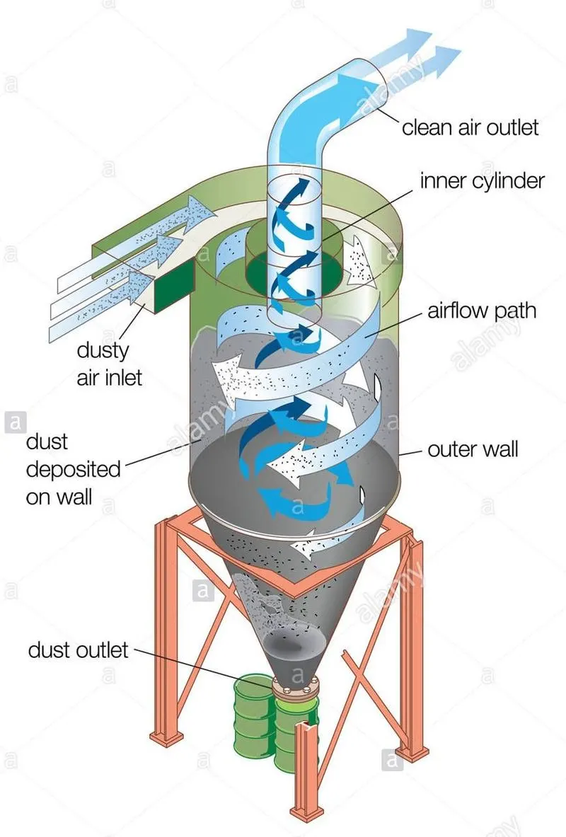
Cyclone separators are separation devices which uses centrifugal force generated by a spinning gas stream to separate particles from the carrier gas. It can be also used for separating particles from liquid , such separators are called hydrocyclone. Such cyclone separators are used in oil refineries , sawmills , cement industry , air pollution control devices etc… These are preferred because of its simple design , cost effectiveness and low maintenance. They are also well suited for high temperature and pressure applications.
The working of a cyclone separator is shown below,
OBJECTIVE
- To carry out simulations for the following two different cases ,
Case 1
To perform analysis by varying the particle size from 1μm to 5μm by keeping the particle velocity and the inlet flow velocity constant at 3m/s.
Case 2
To perform analysis by varying the particle velocity from 1m/s to 5m/s by keeping the particle size constant at 5μm and the inlet flow velocity same as the particle velocity.
- To briefly explain about any four empirical models used to calculate the cyclone separator efficiency.
THEORY
Discrete Phase Modelling (DPM) is used to analyze the behaviour of the particles dispersed in the continuous phase. Such modelling helps in simulating discrete phase problems like aerosol dispersion, liquid fuel combustion , coal combustion etc..
One of the numerical calculation approaches of multiphase flows is Euler-Lagrange approach.
Cyclone separator efficiency
It is defined as the fraction of particles that is retained by the cyclone.
It can be calculated as , `"Collection efficiency" = ("Particles trapped" / "Total particles tracked" )*100`
There are also other complex theories that are developed to predict efficiency.
Four of such complex empirical models used to calculate the cyclone separator efficiency are explained briefly ,
- Iozia and Leith logistic model:- It is modified version of Barth model , which was developed based on force balance. The assumption made in this model is that the particles carried by the vortex endures the influence of two forces namely centrifugal and flow resistance. The collection efficiency according to this model is given as follows,
Collection efficiency , `eta_i = 1/(1+(d_(pc)/d_("pi"))^beta)`
Where , `d_("pi")` is the particle dia , `d_(pc)` is the particle size at which the efficiency is `50%` and `beta` is an expression for slope parameter.
- Li and Wang model:- This model includes particle bounce or re-entrainment and turbulent diffusion at the cyclone wall. From this model a two dimensional analytical expression of particle distribution in the cyclone is derived. The collection efficiency for particle of any size is calculated using the formula,
`eta_i = 1-exp(-lambdatheta_1)`
Where , `theta_1 = 2pi(S+L)/a`
Here , `lambda` is the characteristic value , `theta_1` is the angular coordinate , `S` is the cyclone gas outlet duct length , `L` is the natural length and `a` is the cyclone inlet height.
- Koch and Licht model:- The inherently turbulent nature of cyclones and the distribution of gas residence times within the cyclone were studied and understood in this model. One of the major assumption made in this model was that the tangential velocity of a particle is equal to the tangential velocity of the gas flow. The collection efficiency according to this model is calculated as ,
`eta_i = 1-exp{-2[(Gtau_iQ)/D^3(n+1)]^(0.5/(n+1))}`
Where , `G` is a factor related to the configuration of the cyclone, `Q` is the volumetric gas flow rate , `D` is the cyclone body diameter , `n` is the cyclone vortex exponent and `tau` is the relaxation term.
- Lapple model:- This model is based on force balance without considering the flow resistance. The assumption made was that the particle entering the cyclone is evenly distributed across the inlet opening. The efficiency of collection of any particle size according to this model is given by ,
`eta_i = 1/(1+(d_(pc)/d_("pi"))^2)`
PROCEDURE
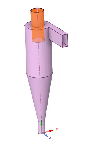
- The 3-D geometry of cyclone separator is processed using space-claim software in ANSYS.
The 3-D geometry is shown below,
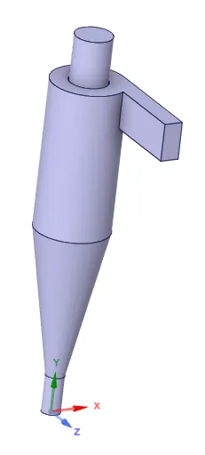
- Now the volume inside this geometry is extracted using volume extract tool.
- This extracted geometry is meshed using ANSYS meshing software. The meshed geometry is shown below,
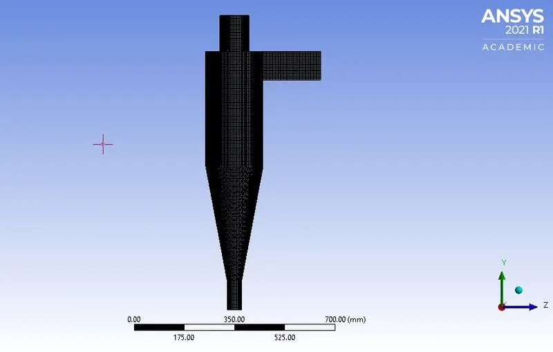
- The method used for meshing is body fitted cartesian with element size of 5mm. The total number of elements is 427841.
- Then the inlet and the outlets are named.
SIMULATION SET-UP
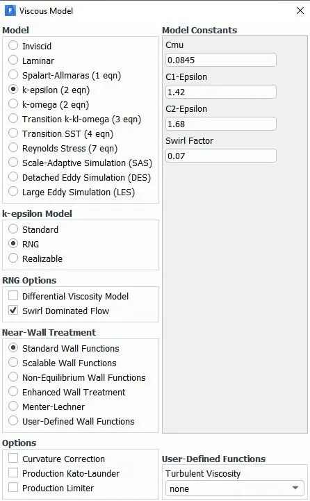
- Pressure based steady state solver is used and the solution scheme is SIMPLE pressure-velocity coupling. Also gravity is enabled.
- The viscous model used is shown below,
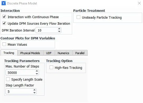
- The DPM setup ,
- Particle injection properties,
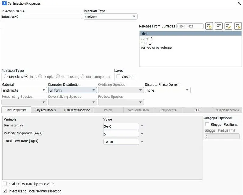
The particle diameter and velocity are changed in this window.
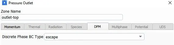
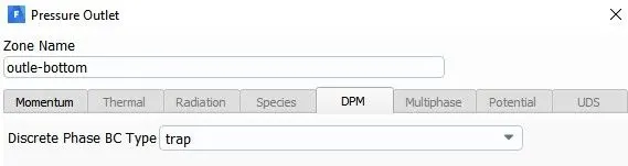
- The DPM boundary condition for the inlet is set to reflect , for the top outlet it is set to escape and for the bottom outlet it is set to trap.
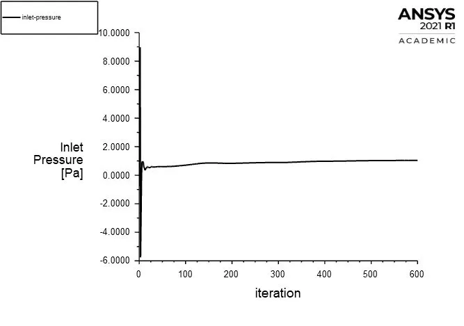
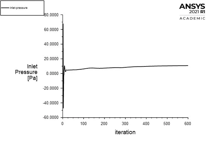
- Inlet static pressure plots are defined under solution definitions using area weighted average method. This inlet pressure value is needed to calculate the pressure drop ,
-
Pressure drop , `DeltaP = "Inlet pressure" - "Sum of outlet pressures"`
Note :- Since the outlet pressure is set to zero , the pressure drop is same as the inlet pressure.
- Standard initialization computed from inlet is done.
- The simulation is run for 600 iterations.
- After the simulation is completed the particle history data is exported as CFD-post file type.
RESULTS
CASE 1
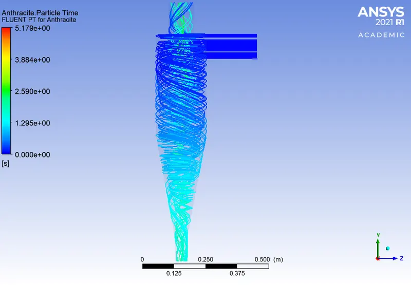
- For particle size = 1μm
Particle tracking with residence time ,
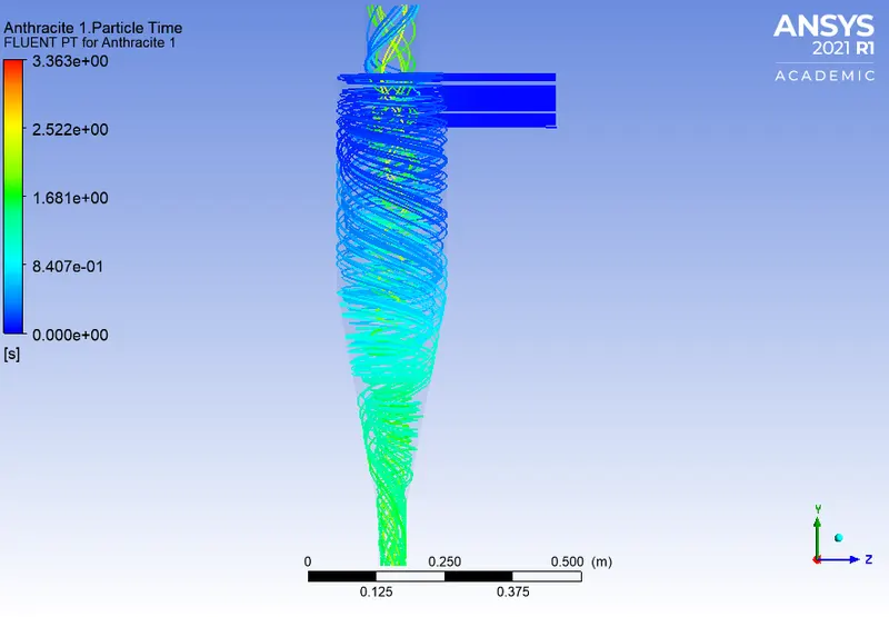
- For particle size = 3μm
Particle tracking with residence time ,
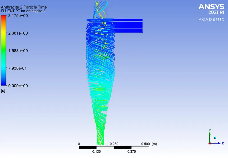
- For particle size = 5μm
Particle tracking with residence time ,
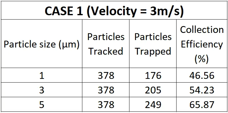
Collection efficiency for the three different particle sizes,
CASE 2
- For velocity = 1m/s
Inlet pressure ,
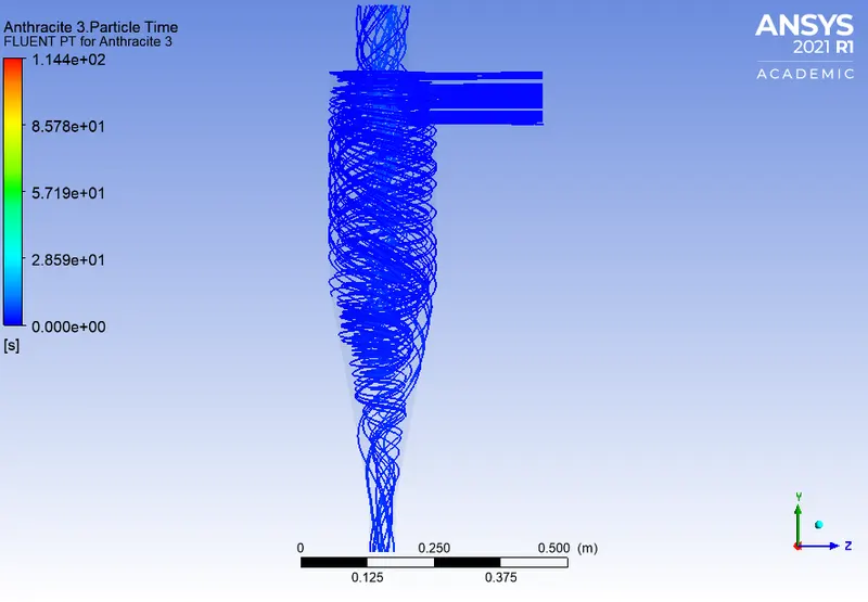
Particle tracking with residence time ,
- For velocity = 3m/s
Inlet pressure ,
Particle tracking with residence time ,
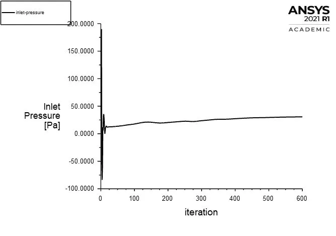
- For velocity = 5m/s
Inlet pressure ,
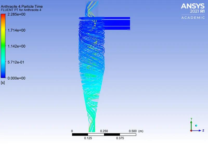
Particle tracking with residence time ,
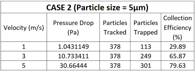
Collection efficiency & the pressure drop for the three different velocities,
CONCLUSION
The simulations to analyze the working of a cyclone separator has been done successfully using ANSYS software. Also the collection efficiency and the pressure drop has been calculated.
The analysis done under Case 1 shows us that the collection efficiency improves as the particle size increases. Hence it can be concluded that the particle size effects the efficiency of a cyclone separator. This correlation between the particle size and the collection efficiency has been validated from the article by Jolius Gimbun et al. [1]
Under case 2 the effect of velocity on the collection efficiency and pressure drop was analyzed. In this case the collection efficiency was significantly improved as the velocity was increased from 1m/s to 5m/s. Hence it could be said that the collection efficiency is enhanced by increasing the inlet gas velocity.
From the tabulated results it is clear that the pressure drop increases with increasing inlet gas velocity. Hence it could be concluded that the pressure drop is directly proportional to the inlet gas velocity value. This relation has been validated from the article the article by B.Wang et al. [2]
REFERENCE