Week 10 - Simulating Combustion of Natural Gas.
AIM
To perform combustion simulation on the combustor model with methane as the fuel using ANSYS software.
INTRODUCTION
The simulation of combustion is an useful method to analyze the combustion process and the particulate emissions caused by it. Using the CFD simulations , the amount of species emitted after combustion can be calculated. Reducing the amount of these particles will help in improving the efficiency of the combustion devices and also will reduce the harmful effects caused by it on the environment.
OBJECTIVE
- To plot the variation of the mass fraction of the different species in the simulation using line probes at different locations of the combustor. The different species are CO2,H2O,CH4,N2,O2,NOX and soot.
- To study the effect of adding water in the fuel on the formation of NOX and soot. Water content to be added in the fuel from 5% to 30% by mole.
THEORY
The reaction taking place in this combustor is ,
`ubrace(CH_4)_("Fuel") + ubrace(ar(O_2+3.76N_2))_("Oxidizer") -> ubrace(aCO_2+bH_2O + cN_2)_("Products")`
This combustion process is known as stoichiometric combustion. In this process all the carbon in the fuel forms carbon dioxide and all the hydrogen forms water in the products.
To find the mass fraction of the oxygen we have to balance the equation and solve for the coefficients.
Comparing the coefficients of oxygen on the reactant and product side we get ,
`2ar= 2a + b` ---Eq(1)
Also we get , `a = 1` and `b = 2` on comparing the coefficients of carbon and hydrogen on both sides. Putting this values in equation (1) we get,
`2ar = 2+2`
`ar = 2`
Hence we have `2` moles of oxygen and `7.52` moles of nitrogen.
Mass of `2` moles of oxygen `= 64`
Mass of `7.52` moles of nitrogen = `210.56`
So mass fraction of oxygen in the oxidizer `= 64/(64+210.56)`
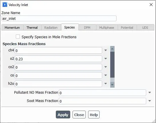
`=0.23`
PROCEDURE
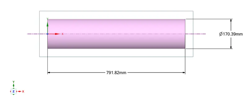
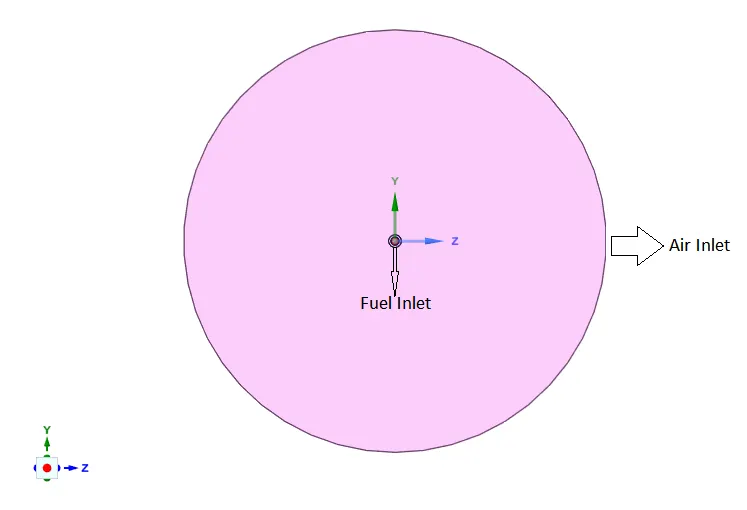
- The 3-D geometry of combustor is processed using space-claim software in ANSYS.
The 3-D geometry is shown below,
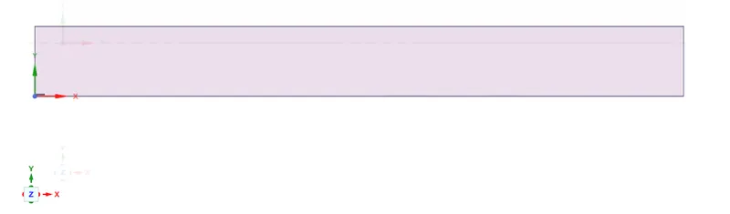
- The 2-D geometry is extracted from this 3-D model by splitting the model into half along both x-axis and y-axis , which will give us the required 2-D geometry shown below,
- This 2-D geometry is meshed using ANSYS meshing software. The meshed geometry is shown below,
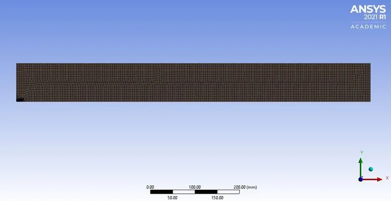
- The method used for meshing is quadrilateral dominant and body sizing has been given to the geometry with an element size of 2mm.
- Also edge sizing is given to the part of the geometry where the fuel and air inlet is separated. The element size given for this edge is 0.5mm.
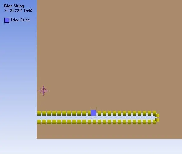
- Total number of elements after meshing is 17036.
- Using the named selection the fuel inlet , air inlet , walls ,axis and the outlet are named.
SIMULATION SET-UP
- Pressure based steady state solver is used and the solution scheme is Coupled pressure-velocity coupling. Also the axisymmetric 2D space is enabled.
- The viscous model used is standard k-epsilon model. The energy equations are used.
- Species transport model is used for the species with volumetric reactions ,
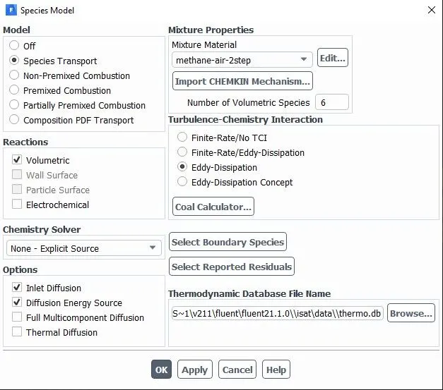
The chemical reaction model used is eddy dissipation model which depends on the turbulence values and the time scale. It is also known as Turbulent chemistry interaction fluent. In this model the ignition takes place without a source as soon as the air and fuel mixes.
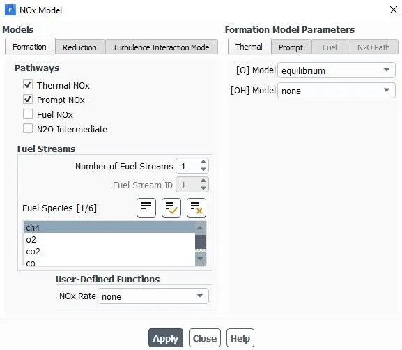
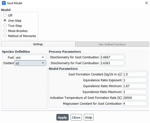
- The NOxand soot models are enabled.
- The inlet boundary conditions are as follows,
Air inlet velocity :- 0.5m/s
Species at air inlet ,
Fuel inlet velocity :- 80m/s
Species at fuel inlet ,
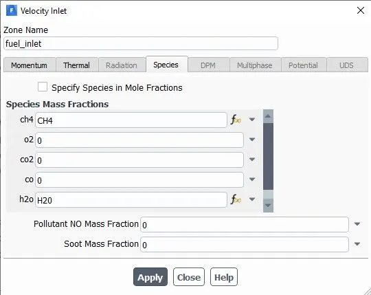
Here the species at fuel inlet are parameterized.
- The outlet boundary condition is set to 0 Pa gauge pressure .
- Report definitions are created using area weighted average method for getting mass fraction of NOx and soot formed at the outlet.
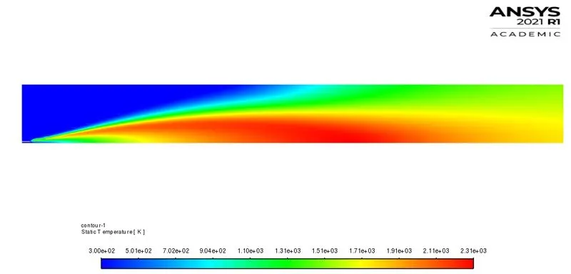
- Also contour plot of static temperature is made.
- Hybrid initialization is done and the simulation is run for 800 iterations.
- After simulation is completed , using the CFD-post software the results are analyzed.
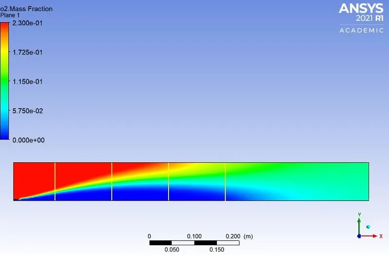
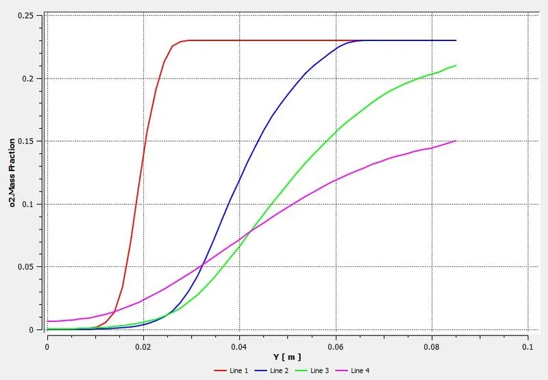
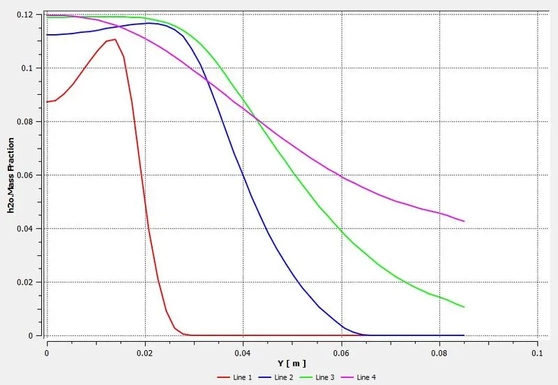
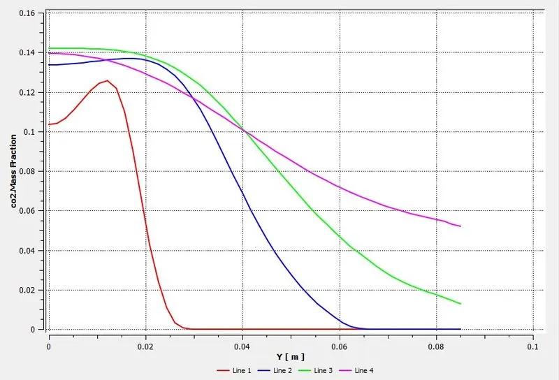
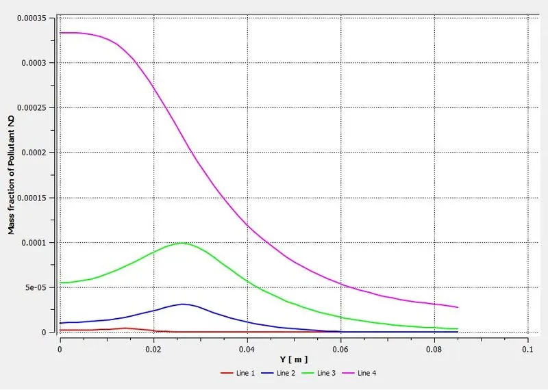
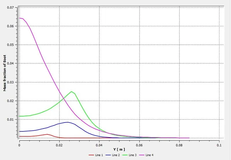
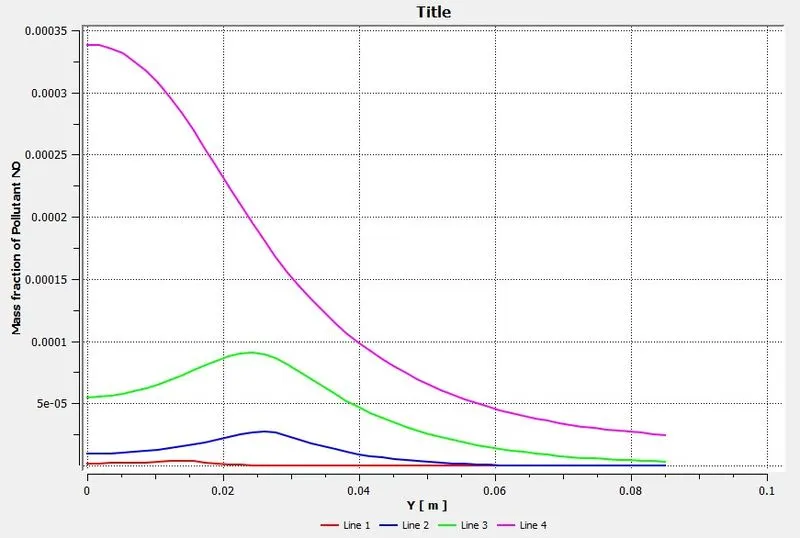
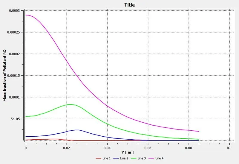
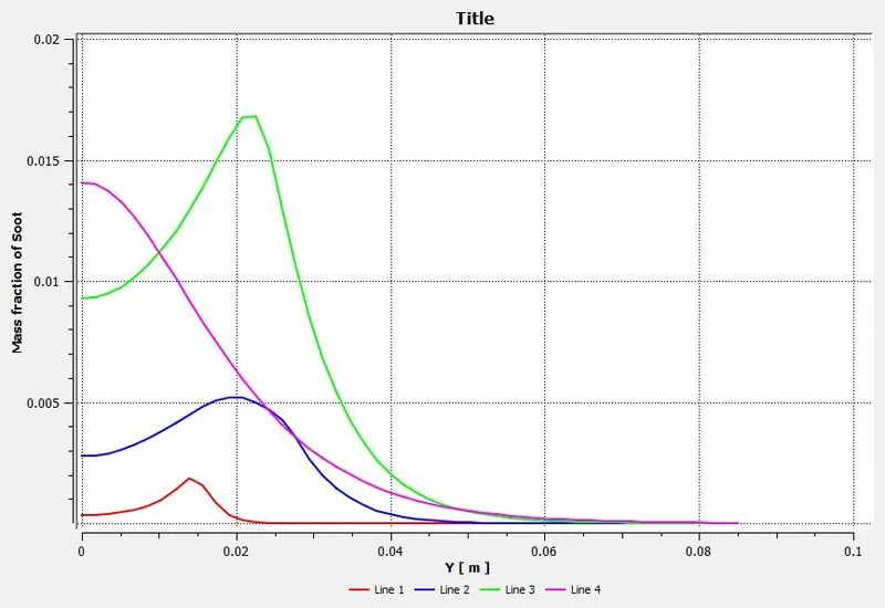
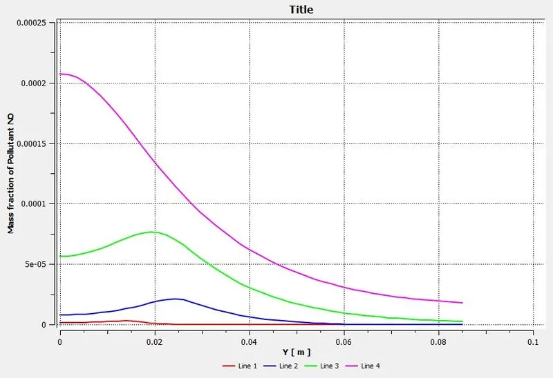
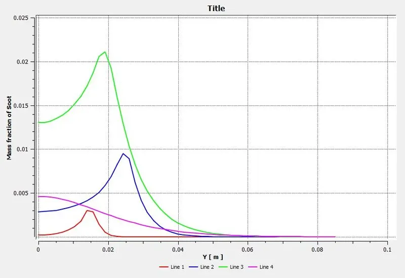
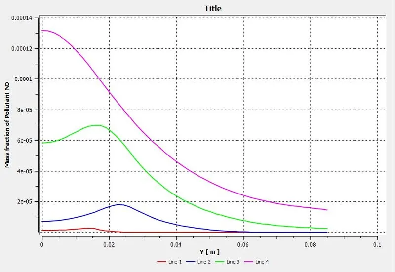
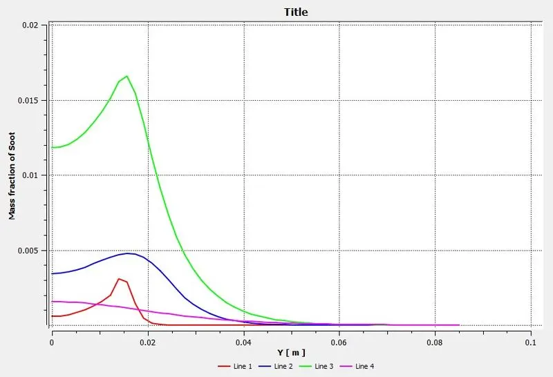
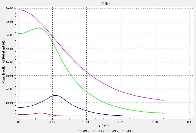
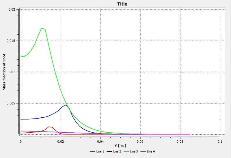
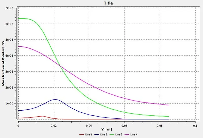
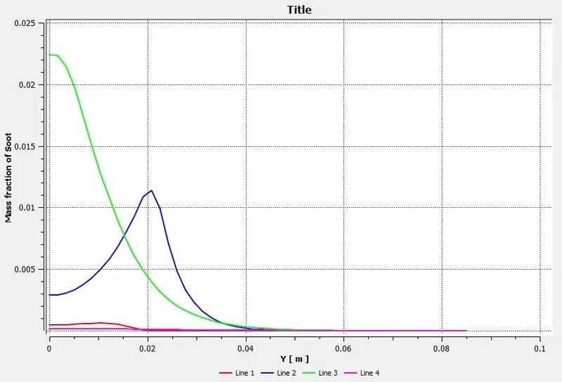
- For this four line probes are place near to the inlet of the combustor. And charts for these 4 line probes are made. The lines are numbered from left to right.
RESULTS
Temperature contour,
Mass fraction of O2,
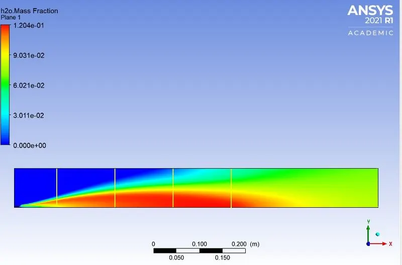
Mass fraction of H2O,
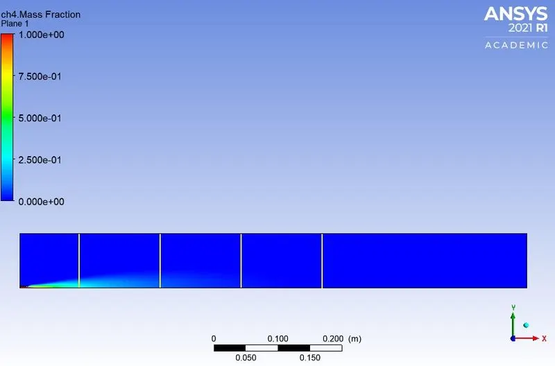
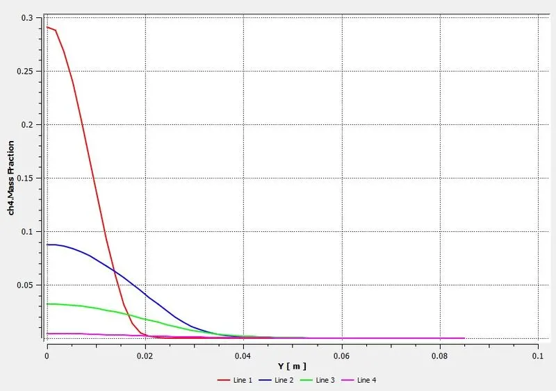
Mass fraction of CH4,
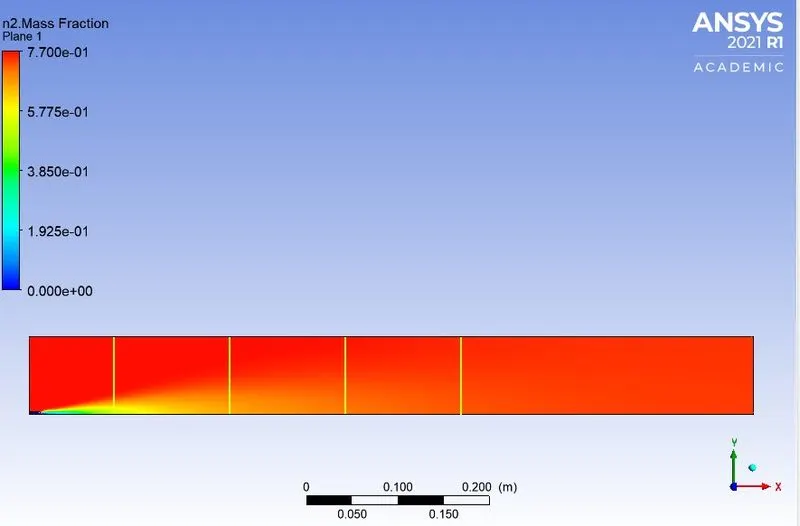
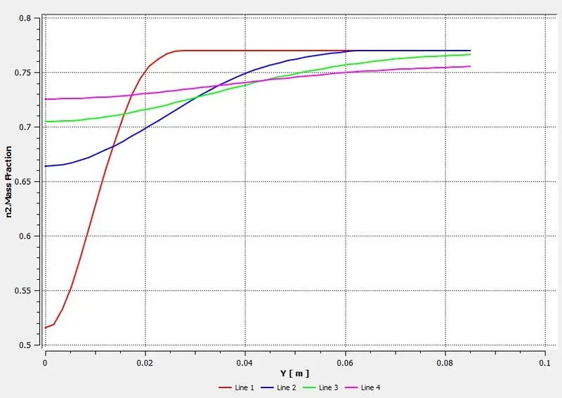
Mass fraction of N2,
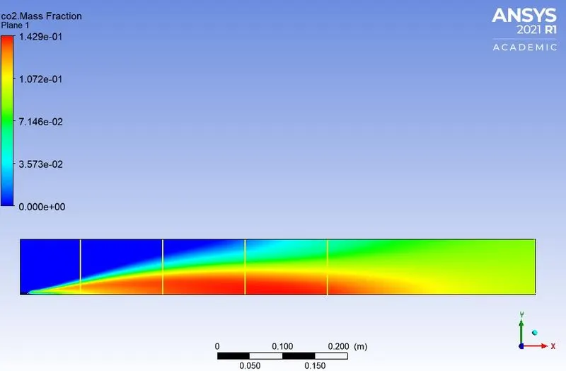
Mass fraction of CO2,
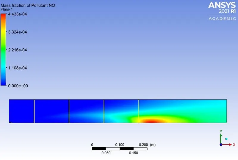
Mass fraction of NOX,
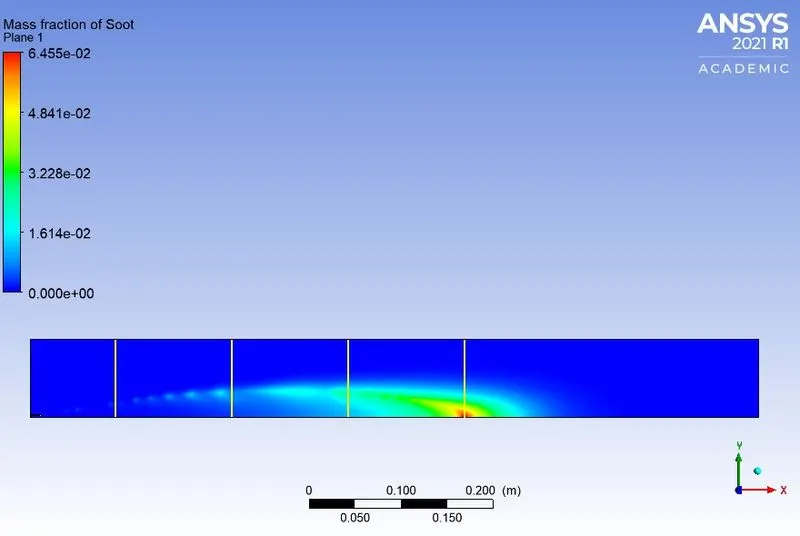
Mass fraction of soot,
Results after adding water into the fuel
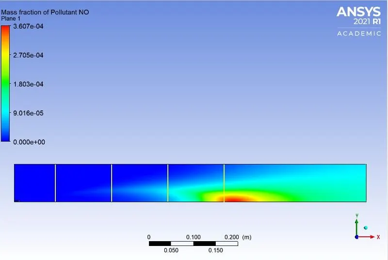
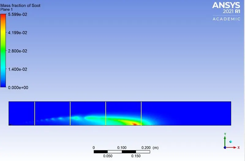
For 5% water,
Mass fraction of NOx,
Mass fraction of soot,

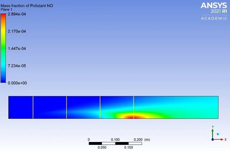
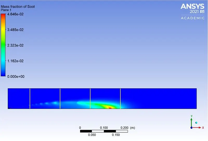
For 10% water,
Mass fraction of NOx,
Mass fraction of soot,
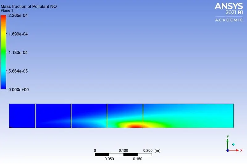
For 15% water,
Mass fraction of NOx,
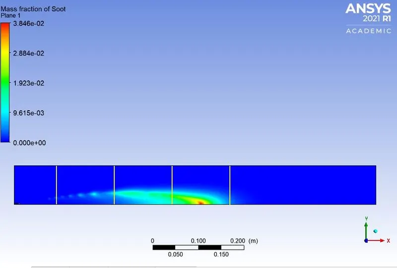
Mass fraction of soot,
For 20% water,
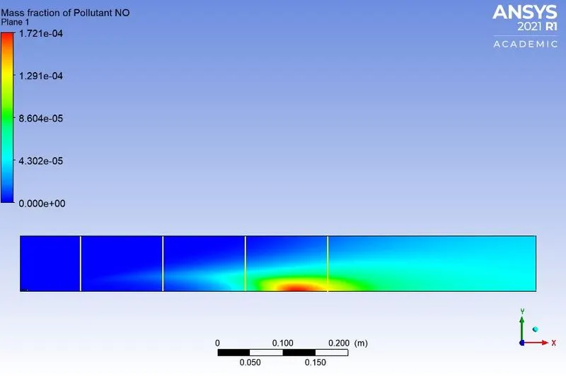
Mass fraction of NOx,
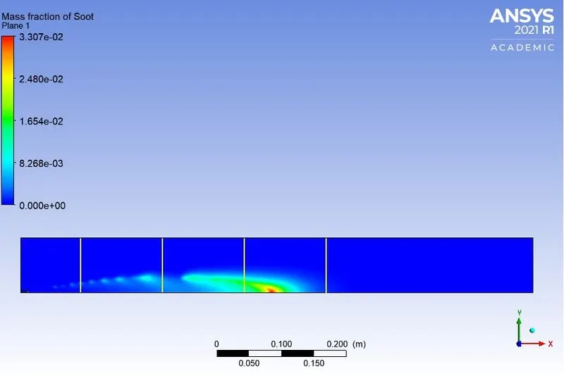
Mass fraction of soot,
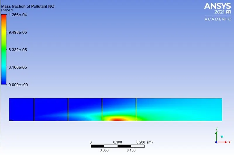
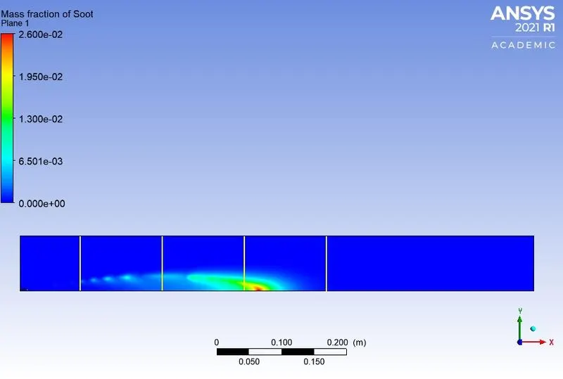
For 25% water,
Mass fraction of NOx,
Mass fraction of soot,
For 30% water,
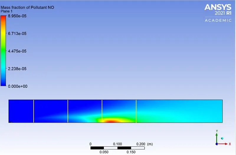
Mass fraction of NOx,
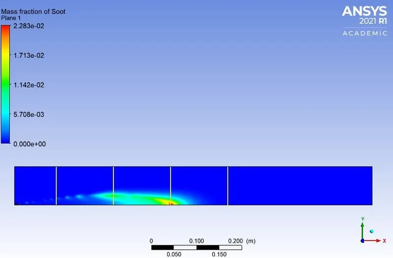
Mass fraction of soot,
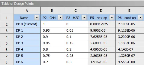
The mass fraction of the NOx and soot at the outlet found using parametric study is shown below,
The effect of adding water on the NOx and soot emissions at the outlet ,
CONCLUSION
The combustion simulation on the combustor model with methane as the fuel has been done successfully using ANSYS software.
Following conclusions can be made for the simulation with no water added,
- The temperature contour shows uniform temperature at the outlet region and maximum towards the middle of the combustor where the combustion takes place.
- The mass fraction of the oxygen is highest at the inlet and it gradually decreases on moving towards the outlet as it is consumed during the reaction.
- The mass fraction of wateris highest towards the middle of combustor and also its more at the bottom part.
- The mass fraction of the fuel used which is methaneis highest at the inlet and it then almost instantly drops its value on moving away from the inlet.
- Nitrogen is present almost uniformly throughout the combustor.
- The mass fraction of carbon dioxide is very high at the bottom part of the combustor throughout its length. But its highest overall concentration inside the combustor happens close to the outlet.
- The mass fraction of nitrous oxide is highest close to the outlet and its accumulated at the bottom part of the combustor.
- Similarly for the mass fraction soot also the values are high at the outlet region and accumulated at the bottom part.
Following conclusions can be made for the simulation after adding water,
- On adding 5% water it could be seen that the mass fraction of nitrous oxide and soot starts decreasing. Another thing notice is that the soot accumulation has started moving away from the outlet.
- Here after it can be seen that as the percentage of water is increased the NOx and soot formation moves away from the outlet and also the maximum mass fraction decreases significantly.
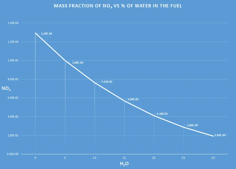
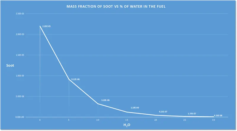
- From the mass fraction emitted at the outlet vs percentage of water added plots it is clear that as the water is added the pollutant emissions starts reducing.
- Also this addition of water has effected soot formation more. This can be seen in the plot where we can see that above 10% of water the soot formation declines so rapidly and remains almost constant after that.
- The effect on NOxis almost linear such that it is indirectly proportional to the water added.
From these results it can be concluded that adding water will decrease the formation of NOx and soot at the outlet of the combustor. Hence adding water will reduce the harmful effects of these pollutants on the environment and humans.