Week 8 - Simulating Cyclone separator with Discrete Phase Modelling
Aim: To perform analysis on cyclone separator and calculate the separation efficiency and pressure drop.
Objective:
- To write a few words about any four empirical models used to calculate the cyclone separator efficiency.
- To perform an analysis on a given cyclone separator model by varying the particle diameter from 1 μm to 5 μm and calculate the separation efficiency in each case. Discuss the results. (Use both the velocity's as 3m/sec).
- To perform an analysis on a given cyclone separator model by varying the particle velocity from 1 m/sec to 5 m/sec and calculate the separation efficiency and pressure drop in each case. Discuss the results. (Use particle diameter size as 5 μm for all cases & keep flow velocity same as particle velocity).
CYCLONE SEPARATOR:
Cyclone separators or simply cyclones are separation devices (dry scubbers) that use the principle of inertia to remove particulate matter from flue gases . Cyclone separators is one of many air pollution removers known as precleaners since they generally remove larger pieces of particulate matter. This prevents finer filtration methods from having to deal with large, more abrasive particles later on. In addition, several cyclone separators can operate in parallel, and this system is known as a multicyclone.
Cyclone separators work much like a centrifuge, but with a continuous feed of dirty air. In a cyclone separator, dirty flue gas is fed into a chamber. The inside of the chamber creates a spiral vortex, similar to a tornado. This spiral formation and the separation is shown in Figure . The lighter components of this gas have less inertia, so it is easier for them to be influenced by the vortex and travel up it. Contrarily, larger components of particulate matter have more inertia and are not as easily influenced by the vortex.
Since these larger particles have difficulty following the high-speed spiral motion of the gas and the vortex, the particles hit the inside walls of the container and drop down into a collection hopper. These chambers are shaped like an upside-down cone to promote the collection of these particles at the bottom of the container. The cleaned flue gas escapes out the top of the chamber.
Four empirical models used to calculate the cyclone separator efficiency :
4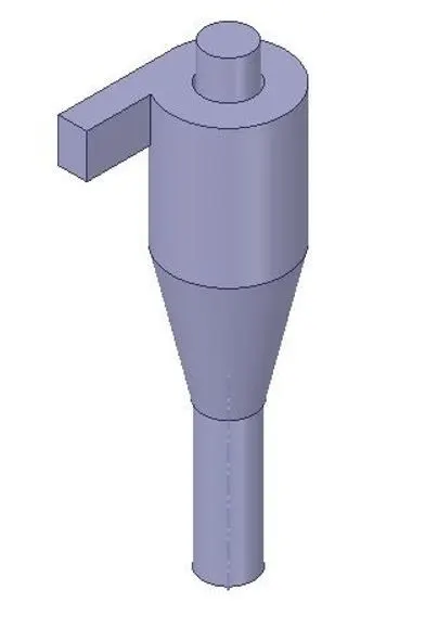
MESHING:
MESH METRIC:
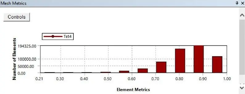
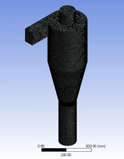
Size Function: Proximity & Curvature
Min Element Size: 10mm
No of Nodes: 113728
No of Elements: 59175 Boundary
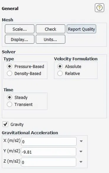
Gravity is enabled in the -ve y-direction.
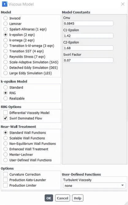
The swirl dominated RNG K-epsilon model is used here to capture the flow more accurately.
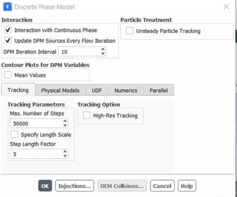
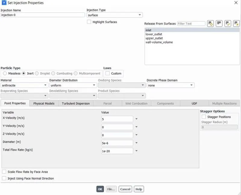
The Discrete phase modeling is used to track the flow of the particles.
No of step for particle tracking = 50000
Injection Material : Anthracite (5microns in diameter)
Velocity Inlet: 3m/s
Outlet: Pressure Outlet( Gauge Pressure= 0Pa)
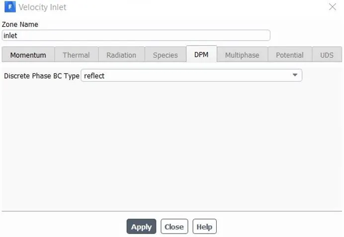
DPM Settings are varied b/w reflect,escape, trap & wall jet.
Reflect: The particle rebounds off the boundary in question with a change in its momentum as defined by the coefficient of restitution.
Escape: Particle escapes out when encountered by the boundary.
Trap: The trajectory calculation is terminated & fate of the particle is recorded as a trap.
Wall-Jet: The wall-jet type boundary condition is applicable for high-temperature walls where no significant liquid film is found & high Weber No impacts when the spray acts as a jet. This model is not applicable to regimes where the film is important.
SOLUTION APPROACH:
RESULTS:
CASE1: In this case, we are making the velocity constant and we are visualizing the difference in results for different particle size.
Results for the particle size of 1 micron with a velocity of 3m/s:
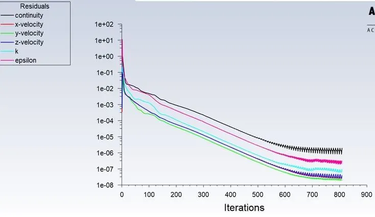
RESIDUAL PLOT:
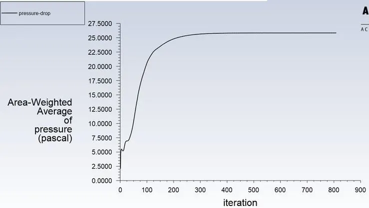
PRESSURE AT INLET:
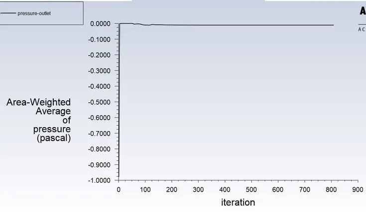
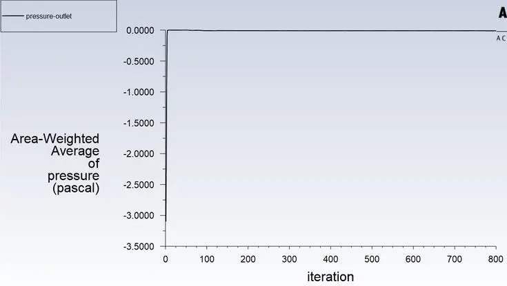
PRESSURE AT OUTLET:

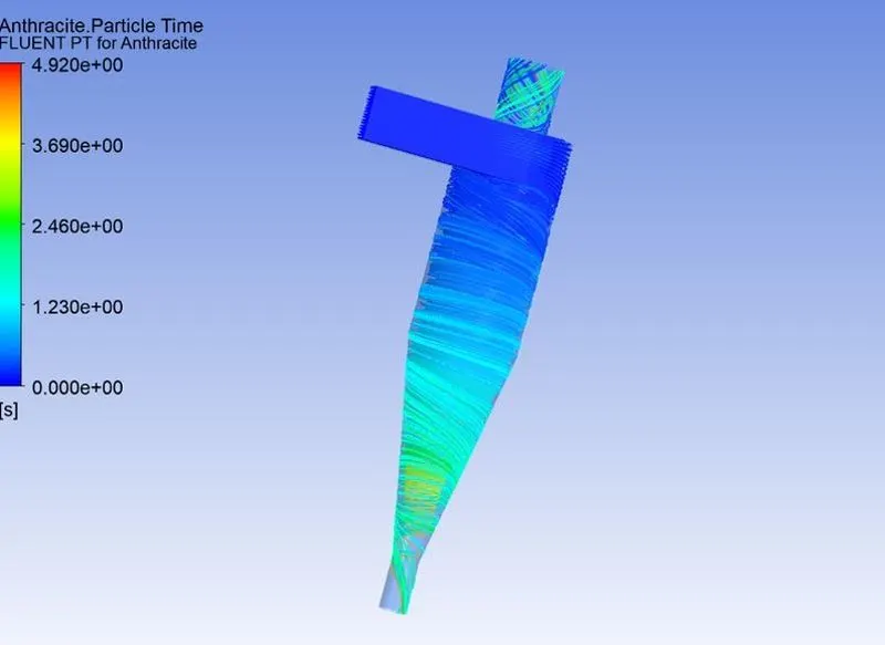
Separation Efficiency in % = (52 / 98) * 100
Separation Efficiency = 53.06 %.
Results for the particle size of 2 micron with a velocity of 3m/s:
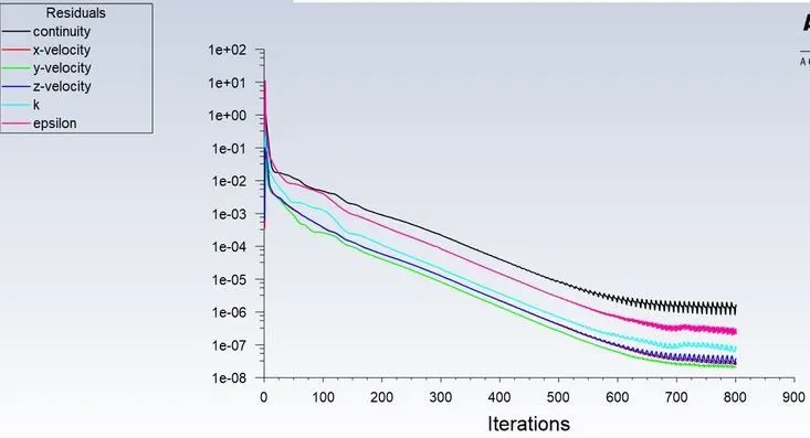
RESIDUAL PLOT:
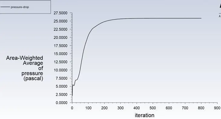
PRESSURE AT INLET:
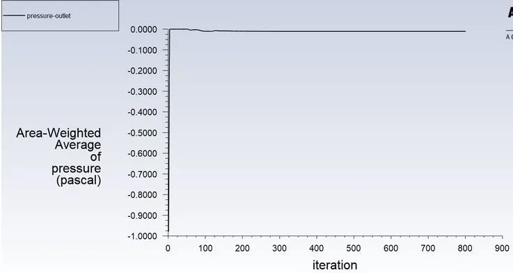
PRESSURE AT OUTLET:
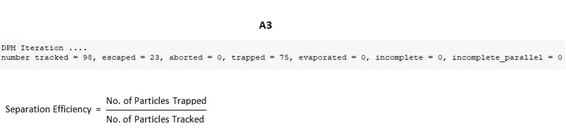
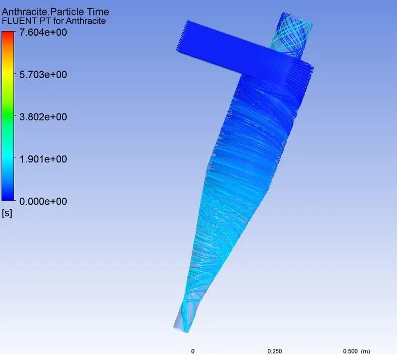
Separation Efficiency in % = (75 / 98) * 100
Separation Efficiency = 76.53 %.
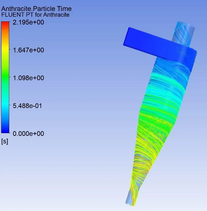
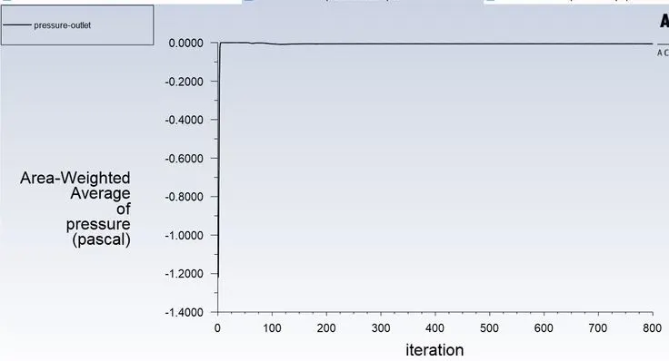
Results for the particle size of 5 micron with a velocity of 3m/s:
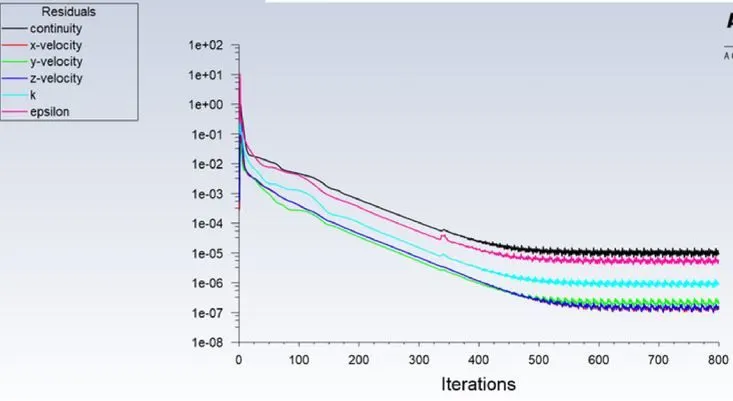
RESIDUAL PLOT:
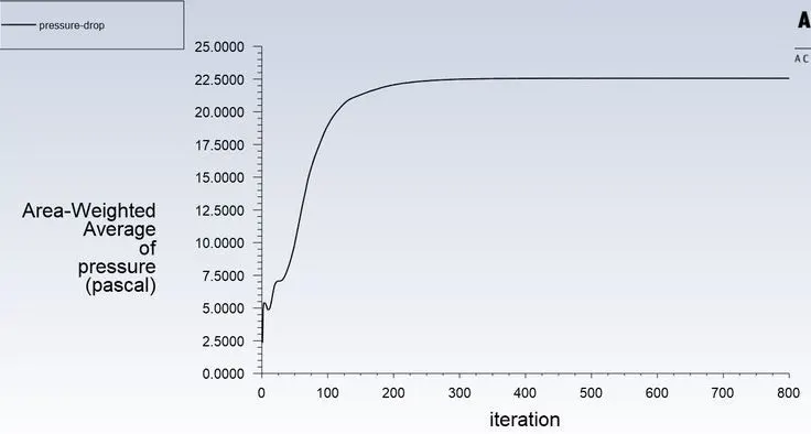
PRESSURE AT INLET:
PRESSURE AT OUTLET:
CASE2: Results for the varying velocity and kepping the particle size constant i.e 5 micron.
Inlet velocity of the particle and the discrete phase is same i.e 1m/s:
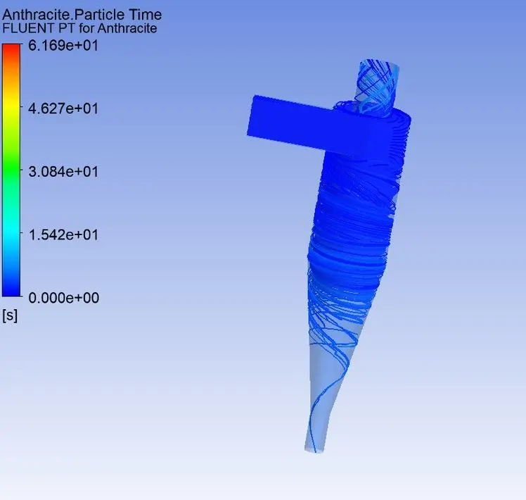
RESIDUAL PLOT:
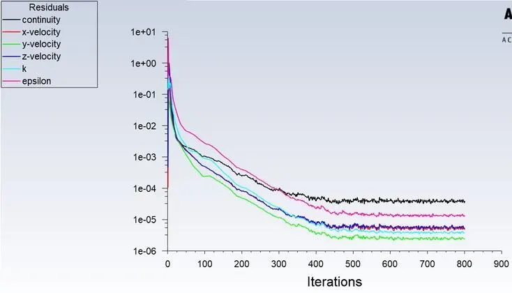
PRESSURE AT INLET:
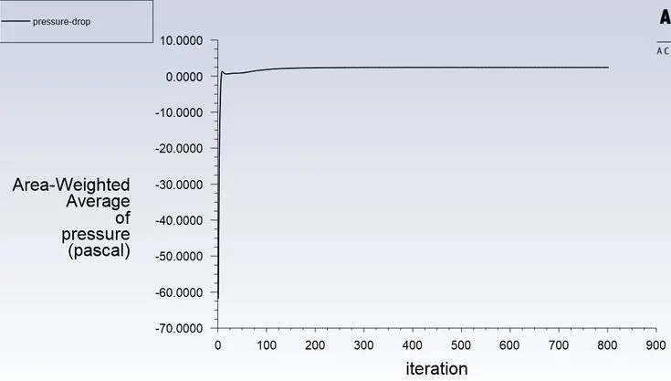
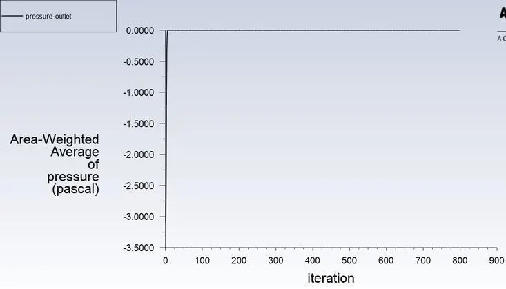
PRESSURE AT OUTLET:
Inlet velocity of the particle and the discrete phase is same i.e 3m/s:
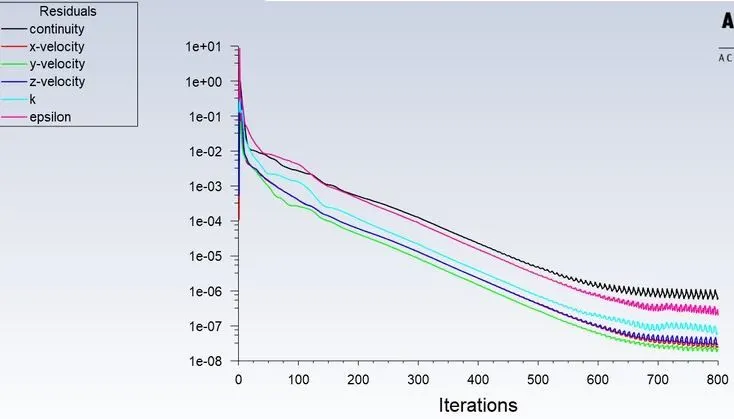
RESIDUAL PLOT:
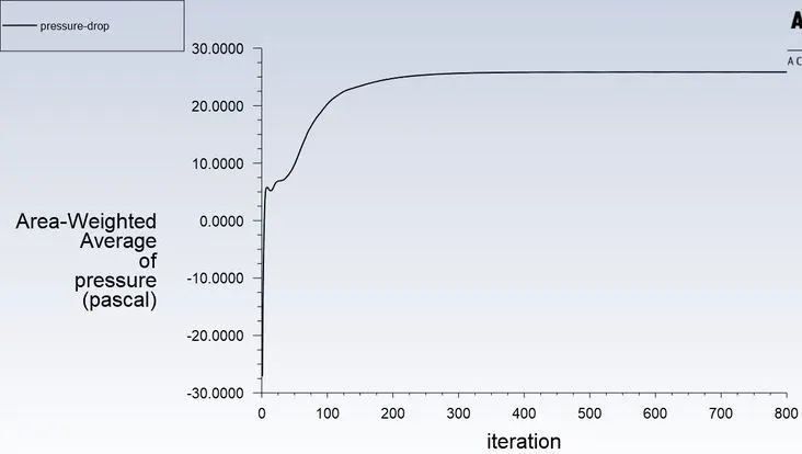
PRESSURE AT INLET:
PRESSURE AT OUTLET:
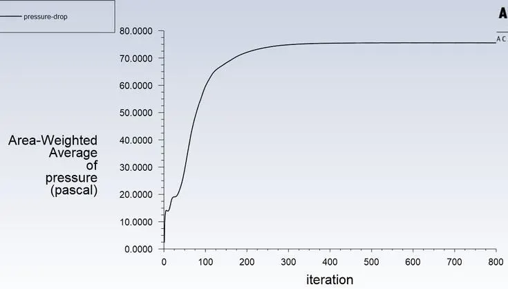
TOTAL PRESSURE:
Pressure drop = Total inlet pressure - Total Outlet Pressure
= 33.93 – 4.09
Pressure drop =29.83 Pa
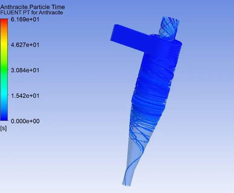
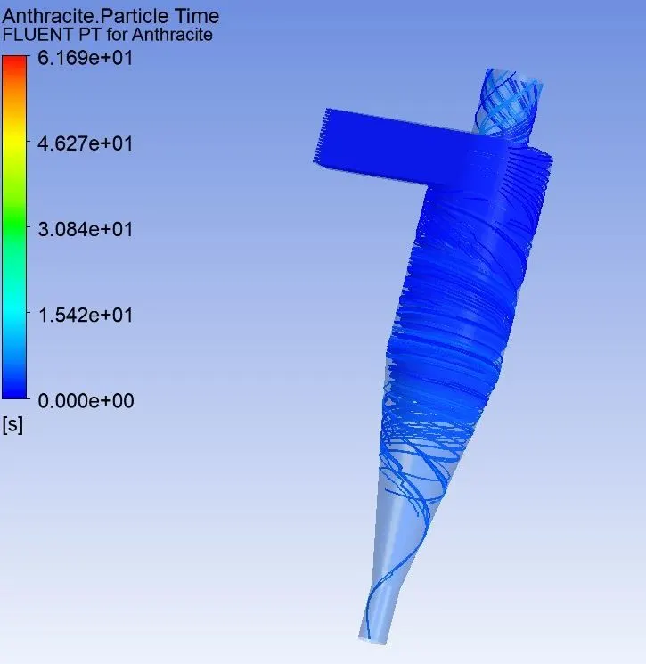
PARTICLE TRACKING:
Separation Efficiency in % = (98 / 98) * 100
Separation Efficiency = 100 %.
Inlet velocity of the particle and the discrete phase is same i.e 5m/s:
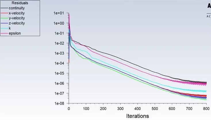
RESIDUAL PLOT:
PRESSURE AT INLET:
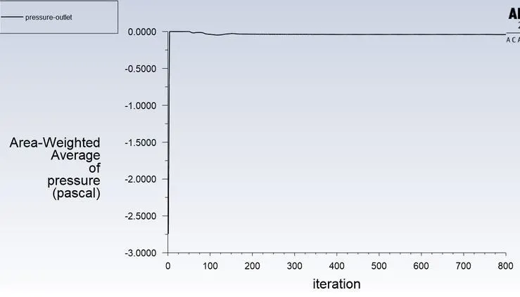
PRESSURE AT OUTLET:
TOTAL PRESSURE:
Pressure drop = Total inlet pressure - Total Outlet Pressure
= 98.93 – 12.04
Pressure drop =86.89 Pa
PARTICLE TRACKING:
Separation Efficiency in % = (98 / 98) * 100
Separation Efficiency = 100 %.
CONCLUSION:
1. Simulation is done for particle size varying from 1 m to 5 m with air and particle velocity as 3m/s. From the video, it is observed that heavier particle is trapped at the bottom outlet and lighter particles are escaped at the outlet 1. But we can also see that lighter particles also get trapped at the bottom outlet because of interaction between lighter and heavier particles and there is an exchange of inertial forces between them as a result there is a transfer of Kinetic energy from heavier particle to the lighter particle, as a result, we can observe a certain number of heavier particles escapes through the top outlet.The collection efficiency of cyclones varies as a function of particle size, density, and cyclone design.
2. Cyclone efficiency will generally increase with the increase in particle size, density, inlet duct velocity, cyclone body length, number of gas revolutions in the cyclone, the ratio of cyclone body diameter to gas exit diameter, inlet dust loading, smoothness of the cyclone inner wall.
3. The efficiency of the cyclone will decrease with an increase in the parameters such as gas viscosity, cyclone body diameter, gas exit diameter, gas inlet duct area, gas density, leakage of air into dust outlet. With the increase in inlet velocity or particle size the efficiency increases..
4. Pressure drop occurs because of the following components:
- Loss due to the expansion of gas in the cyclone chamber.
- Loss due to rotational kinetic energy.
- Loss due to wall frictional forces.