Week 10 - Simulating Combustion of Natural Gas.
Aim: Perform a combustion simulation of Natural Gas in ANSYS Fluent.
Objectives:
Part I
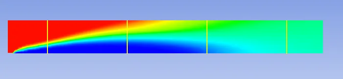
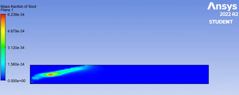
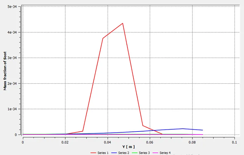
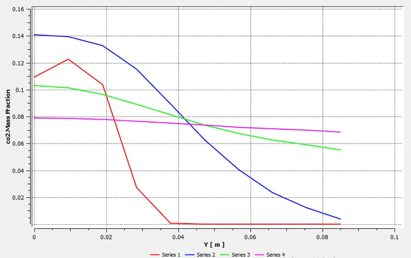
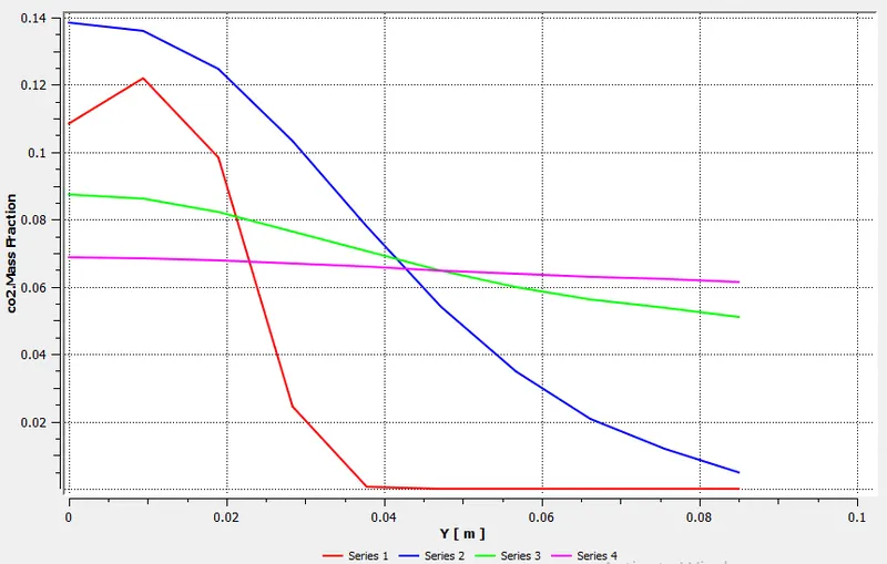
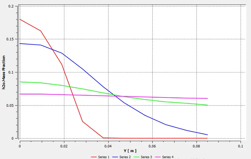
Perform a combustion simulation on the combustor model and plot the variation of the mass fraction of the different species’ in the simulation using line probes at different locations of the combustor as shown in Fig. You need to plot for CO2, H2O, CH4, N2, O2, NOx emissions & Soot formation.
Part II
As you must have observed from the above simulation, the Nox and soot are getting formed at the outlet of the combustor. Such formation has harmful effects on the environment and humans. The stringent government norms also demand the least formation of Nox and soot and to satisfy those requirements, you need to check the effect of adding the water in the fuel.
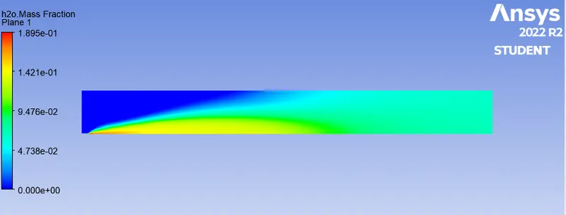
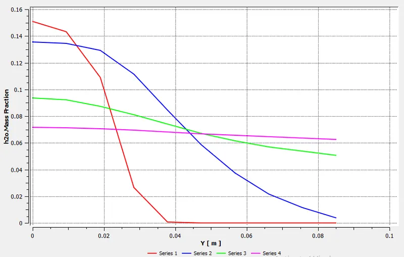
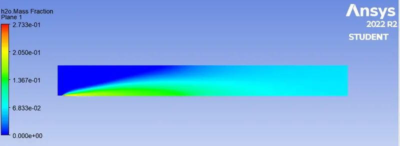
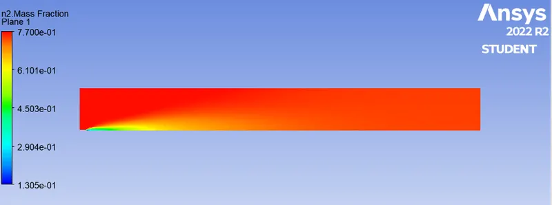
In this part, you need to add the water content in the fuel from 5% to 30% by mole and observe the effect of it on the results. It is necessary to provide line plots and contours to prove your claim.
Chemical kinetics:
Chemical kinetics, also known as reaction kinetics, is the branch of physical chemistry that is concerned with understanding the rates of chemical reactions. It is to be contrasted with thermodynamics, which deals with the direction in which a process occurs but in itself tells nothing about its rate.
Chemical reaction model:
Chemical reaction models transform physical knowledge into a mathematical formulation that can be utilized in computational simulation of practical problems in chemical engineering
1. Geometry:
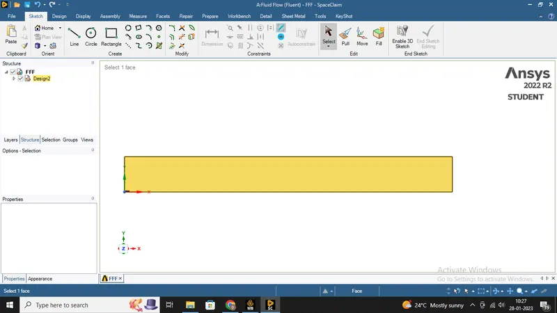
a. Upload the combustor model onto SpaceClaim, since it is a 3D model and we are only interested in the 2D geometry of the combustor. Therefore, we need to split the body by 3/4th and select the plane XY plane region of geometry since we are using the axisymmetric condition.
3D model of the combustor:
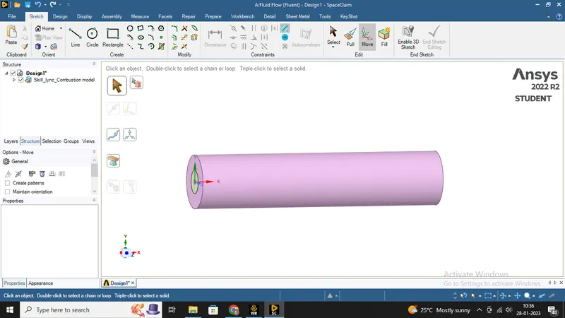
- This is 3D model, we can't run simulation for entire 3D model, it will cost a lot interms of time.
- So instead of 3D, We will perform simulation on 2D geometry, which is Axis-symmetric.
- For 2D geomerty we have to cut 3D model in two parts, and extract 2D geometry of the quadrant portion.
- we merge all faces by using 'combine' command and can make it a single object.
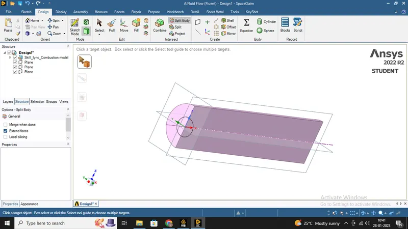
- Then we copy all faces from X-Y plane and paste it in New Design
- Then we paste it only in X-Y plane.
- So the 2D geometry can be ready for further process
2. Mesh setup:
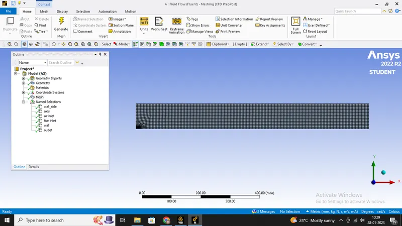
a. Generate base mesh with capture proximity settings and set the cell gap to 3 cells or as per your requirement.
Mesh settings:
b. Provide name selections for the necessary inlets, outlet and walls.
3. Fluent setup:
General settings:
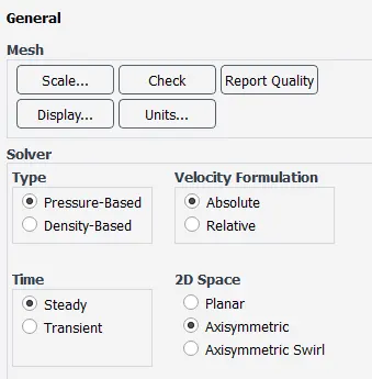
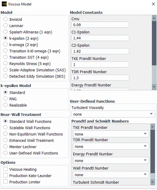
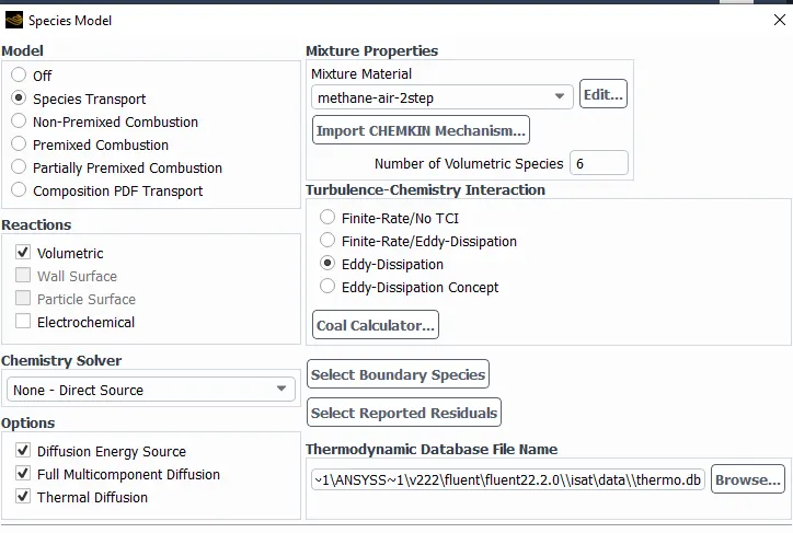
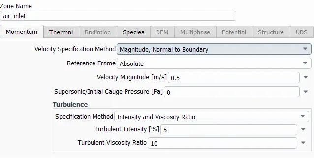
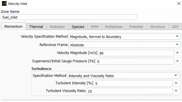
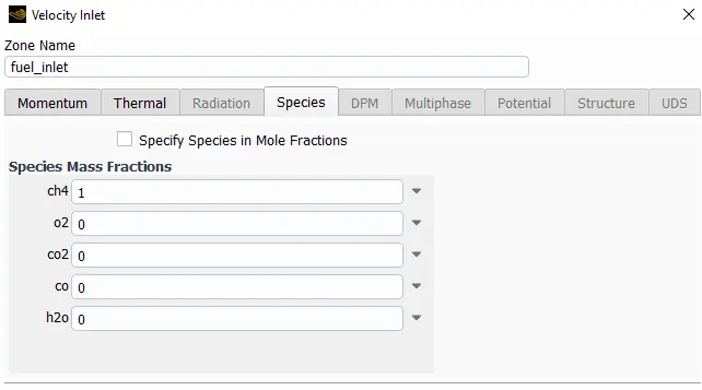
Activate NOx and Soot model:
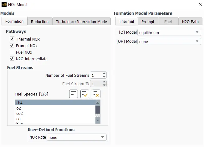
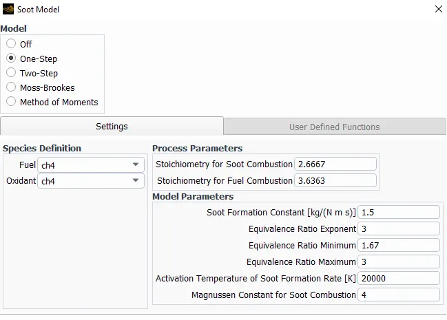
Results and discussion:
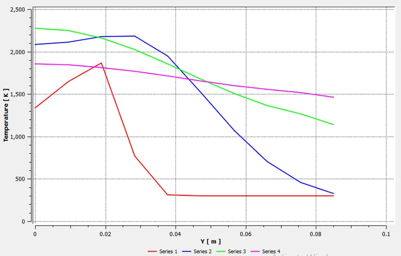
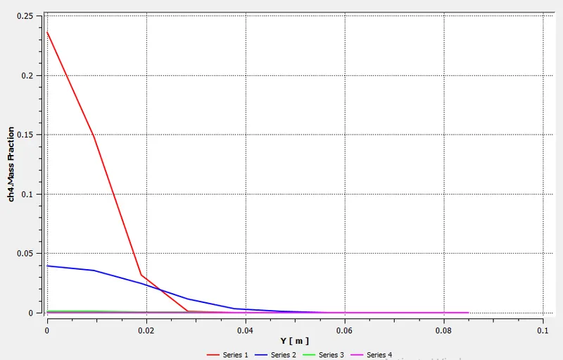
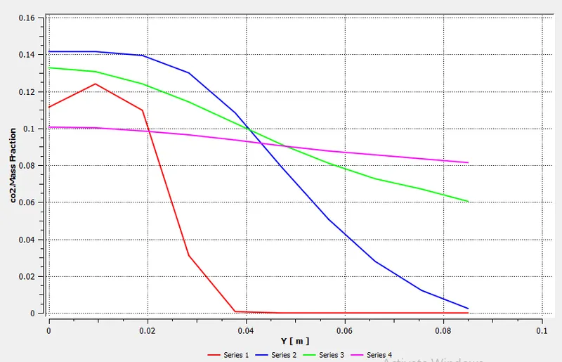
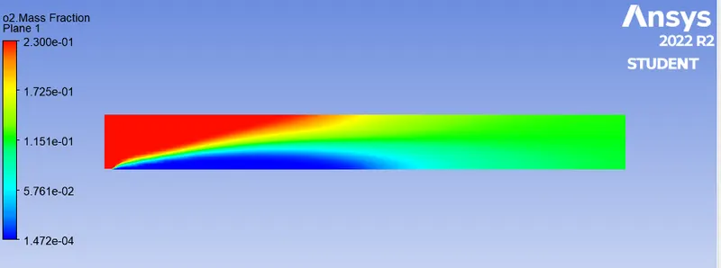
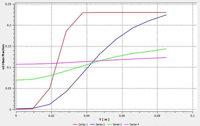
With help of line probes, we can plot the variation of Mass fraction at different locations.
For that we have to create line probe at different locations.
Line probes at different location can be created as given below:
Part I:
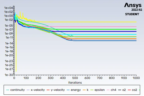
Residuals
Temperature
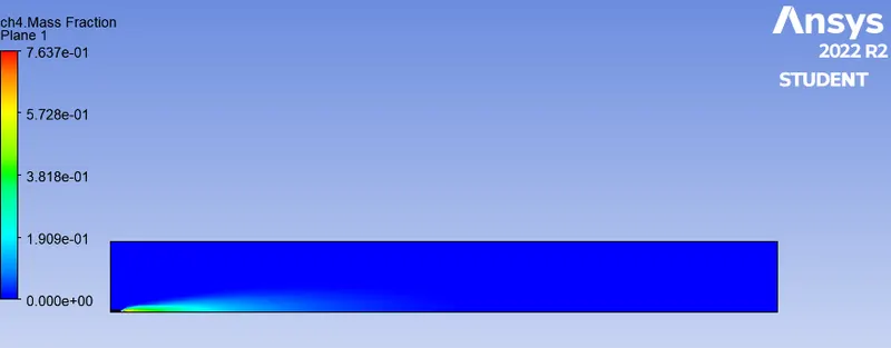
CH4 mass fraction
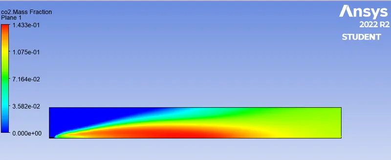
CO2 mass fraction
H2O mass fraction
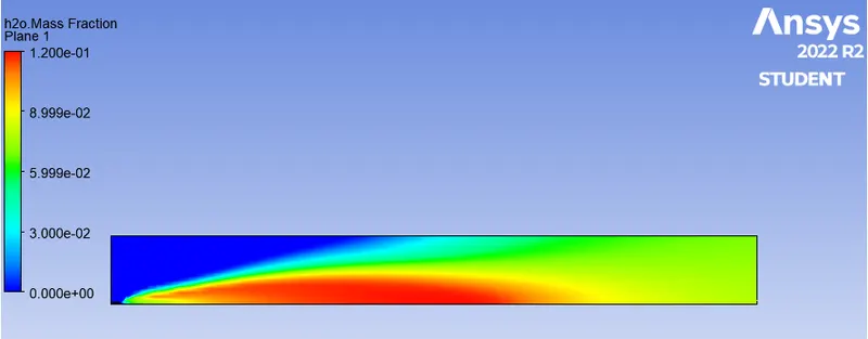
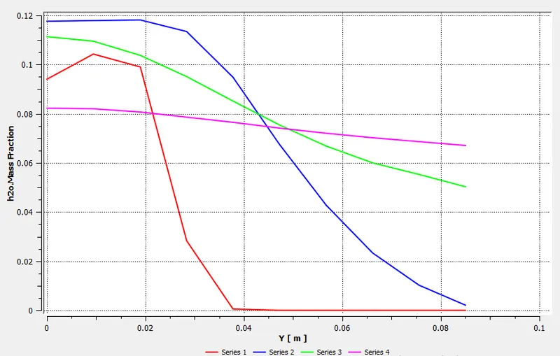
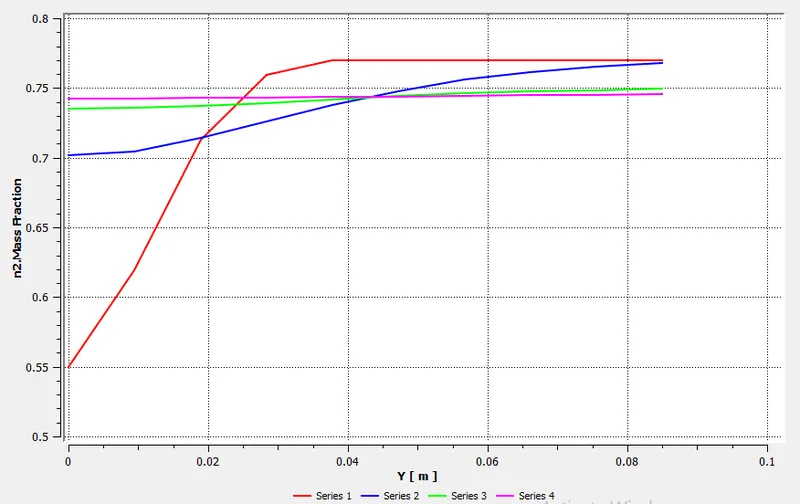
N2 mass fraction
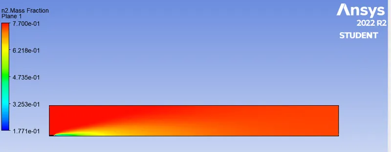
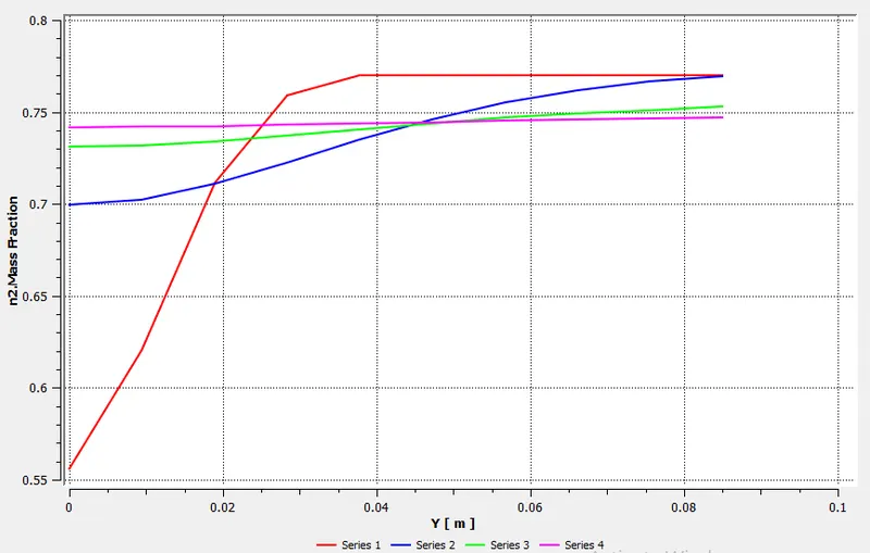
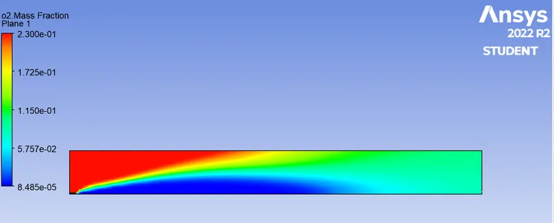
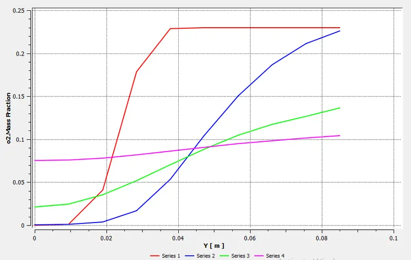
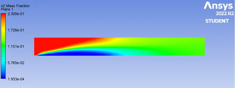
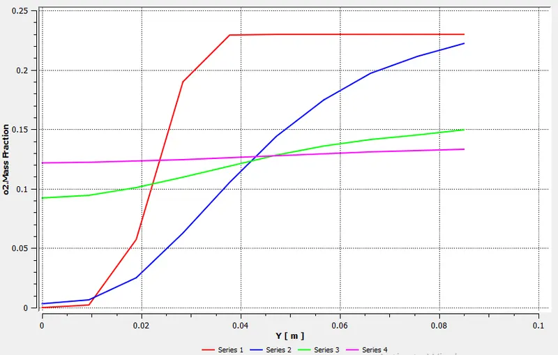
O2 mass fraction
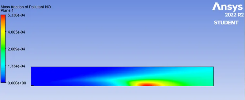
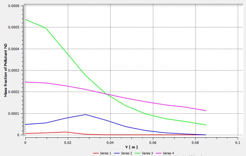
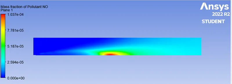
Mass fraction of NO
Mass fraction of soot
Part II
Case I: 5% H2O and 95% CH4
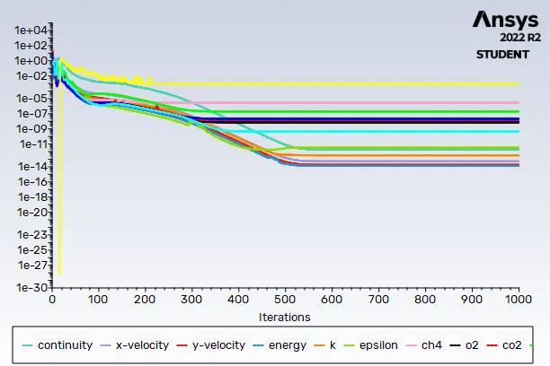
Residuals
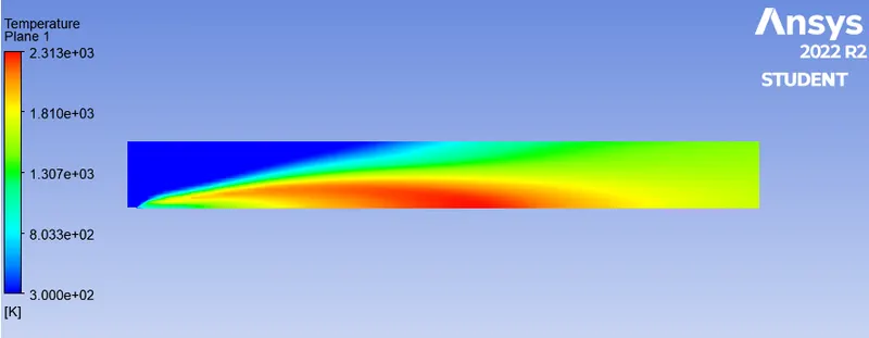
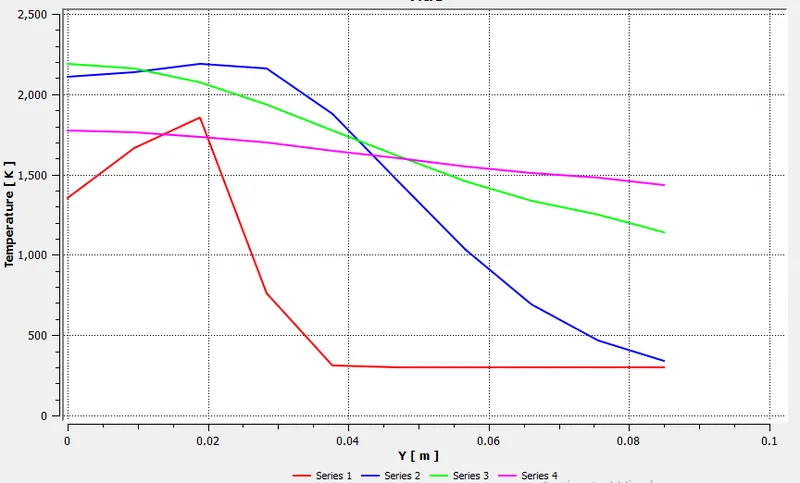
Temperature
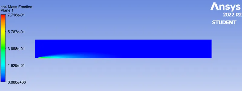
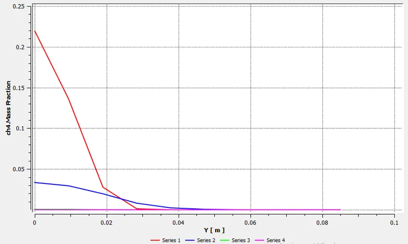
CH4 mass fraction
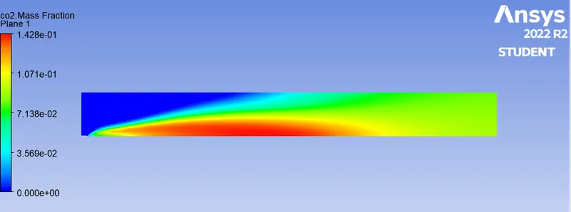
CO2 mass fraction
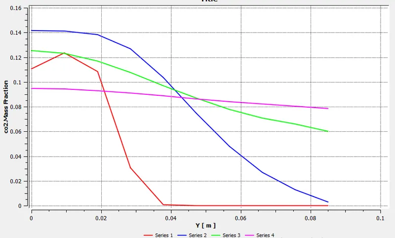
H2O mass fraction
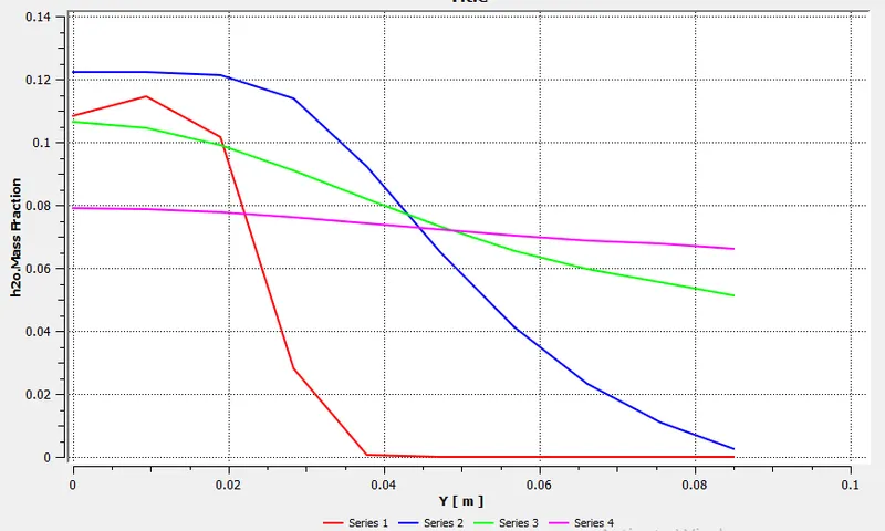
N2 mass fraction
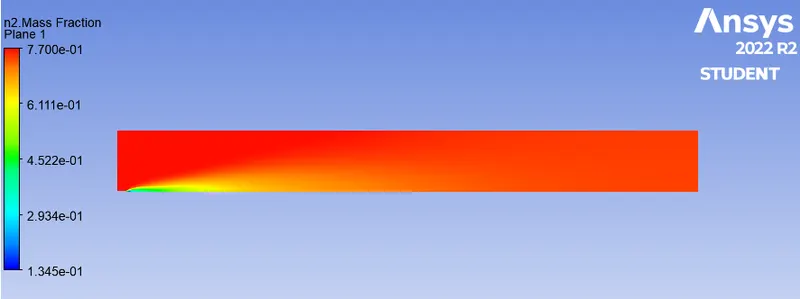
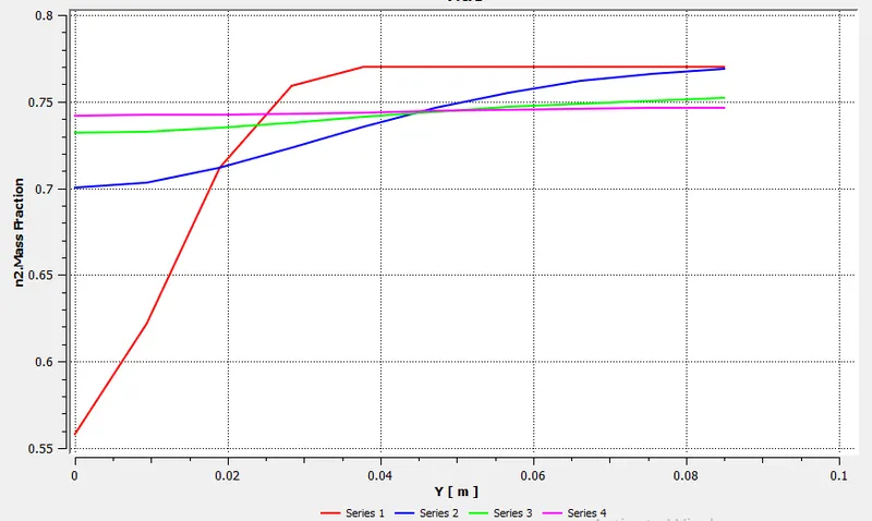
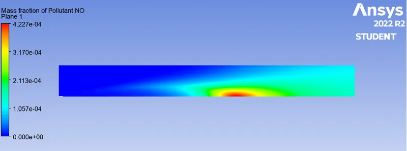
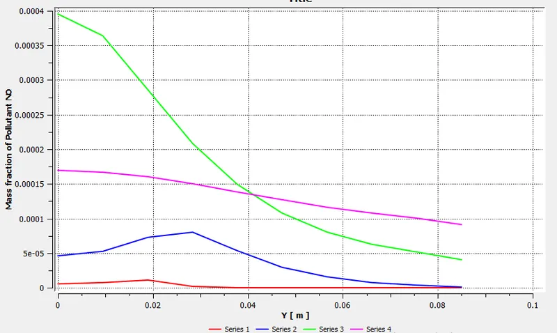
NO mass fraction
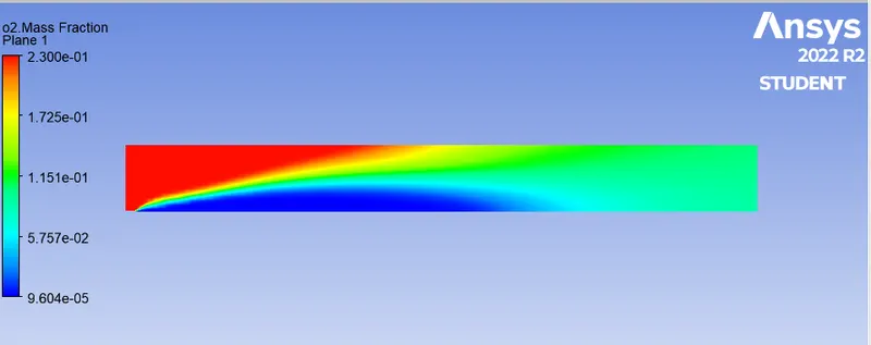
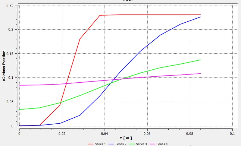
O2 mass fraction
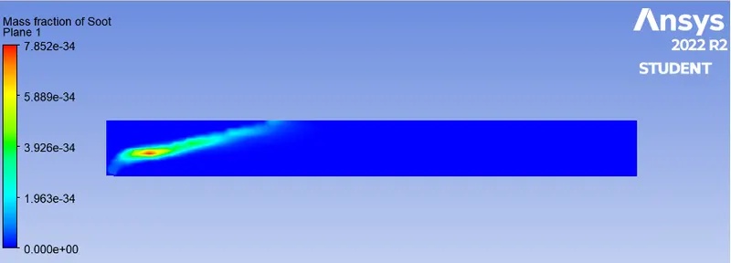
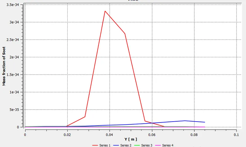
Soot mass fraction
Part II
Case II: 20% H2O and 80% CH4
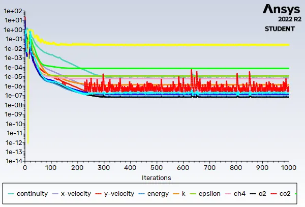
Residuals
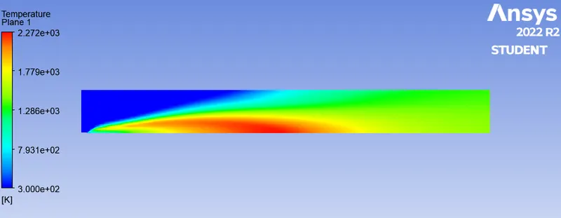
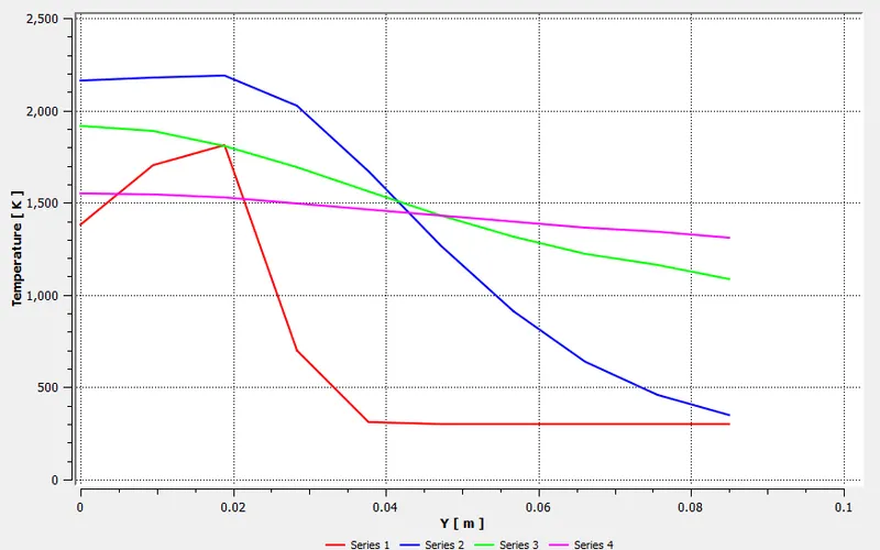
Temperature
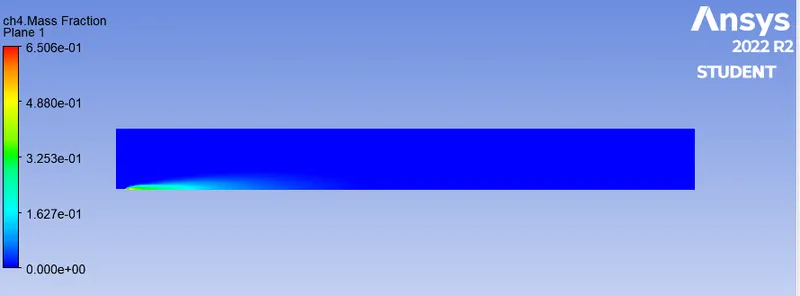
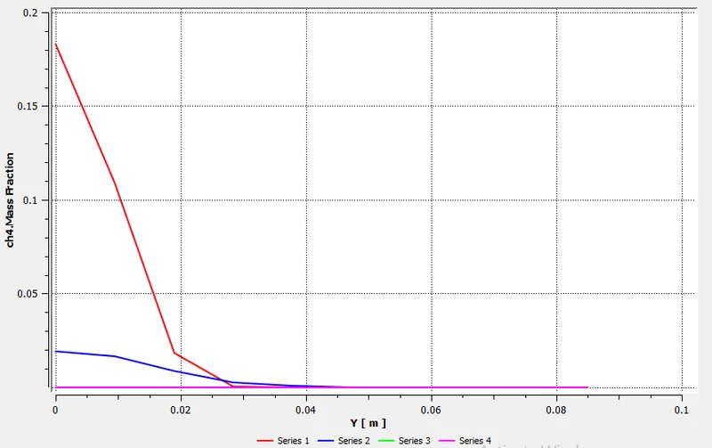
CH4 mass fraction
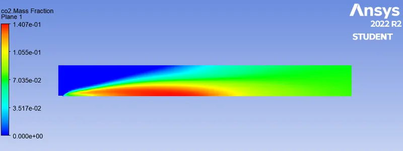
CO2 mass fraction
H2O mass fraction
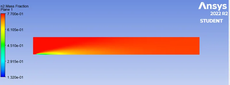
N2 mass fraction
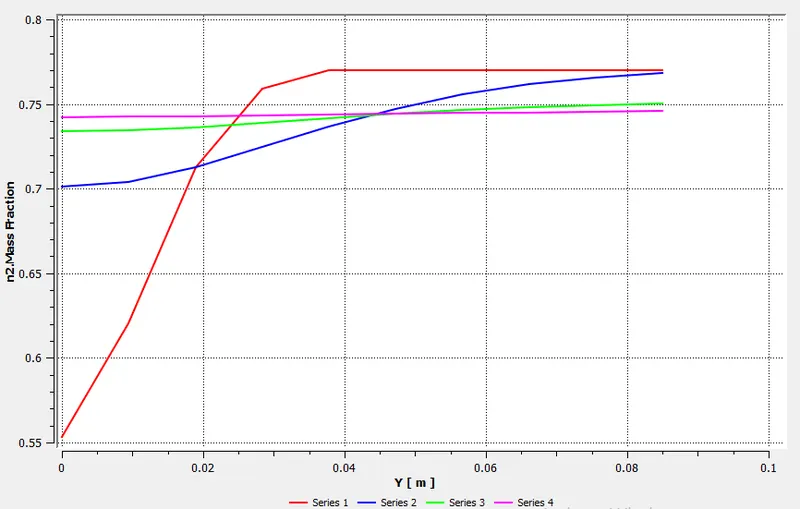
O2 mass fraction
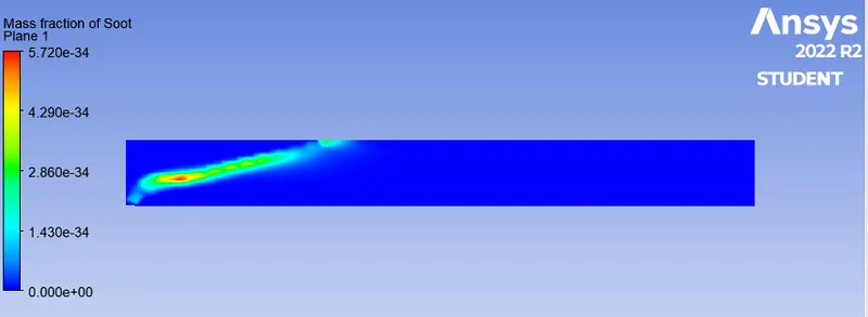
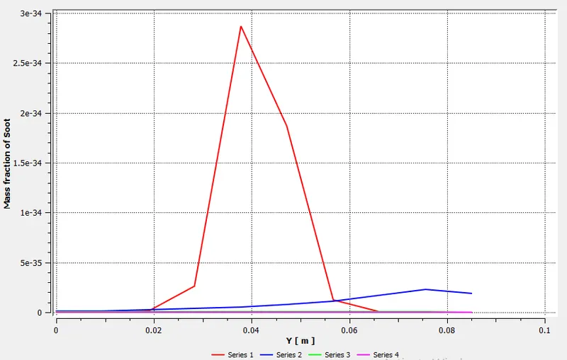
Soot mass fraction
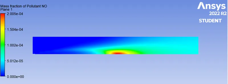
NO mass fraction

Part II
Case III: 30% H2O and 70% CH4
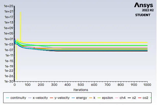
Residuals
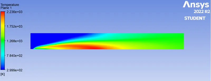
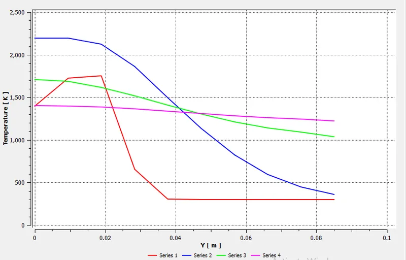
Temperature
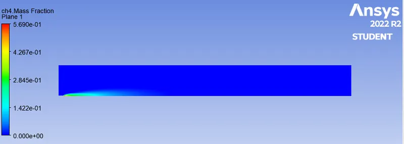
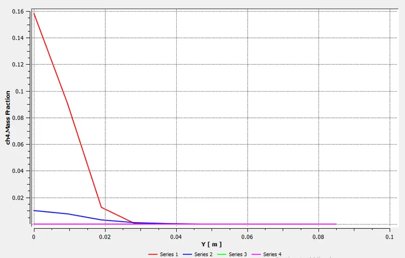
CH4 mass fraction
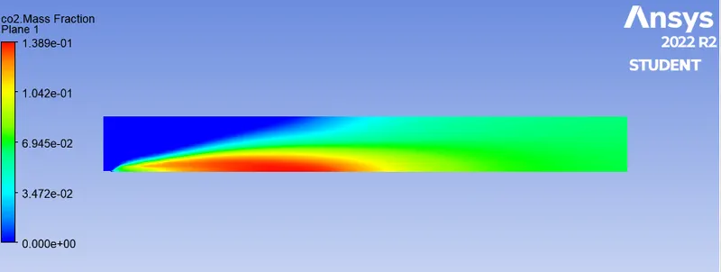
CO2 mass fraction
H2O mass fraction
N2 mass fraction
O2 mass fraction
NO mass fraction
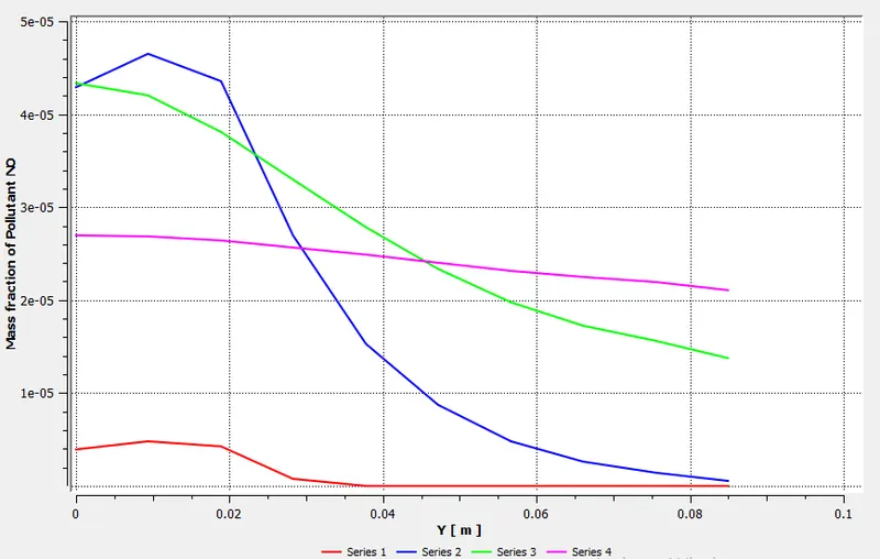
Soot mass fraction
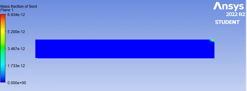
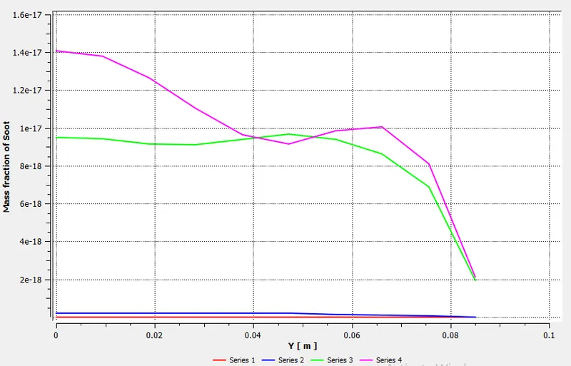
From the results following observations can be made-
- We can see that from the begining, CH4 is burning from high at 1 to near 0. But in real there are some unburnt carbon particles always remains.
- Due to this incomplete combustion of hydrocarbons, generation of SOOT or Fly Ash happens.
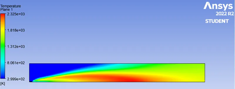
- We can see there are NOx emissions, which are due to the combustion of nitrogen present in the air, which is 78% and it is directly related to the maximum temperature generated inside the burner.
Conclusion:-
- Adding water from 5% to 30% decreases the emission of Nox and Soot pollutants.
- Adding water also decreases the highest temperature.
- Highest temperature is achieved in the proximity of the Inlet.
- Low combustion temperature provides a number of advanced combustion strategies, including homogeneous charge compression ignition (HCCI) or premixed charge compression ignition (PCCI). LTC combustion can produce very low emissions of NOx and PM but often results in increased CO and HC.