Week 6 - CHT Analysis on a Graphics card
Aim:
Perform a steady-state conjugate heat transfer analysis on a model of a graphics card.
Objectives:
- Run the simulation by varying the velocity from 1m/sec to 5m/sec for at least 3 velocities and discuss the results.
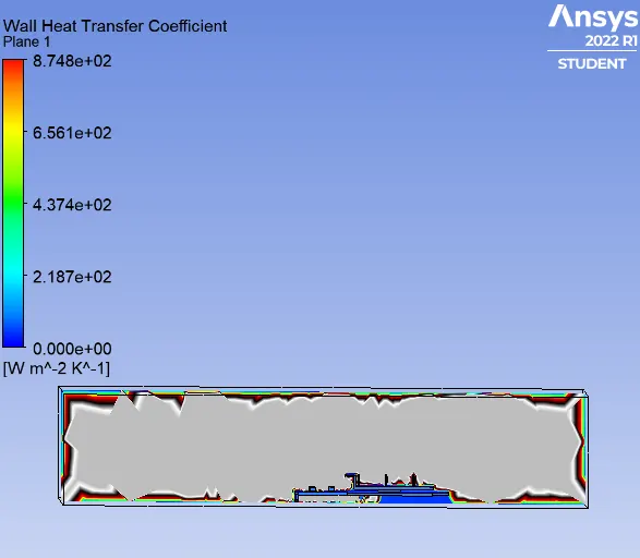
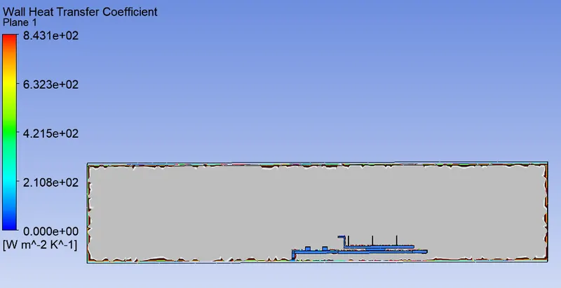
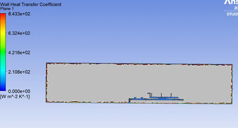
- Find out the maximum temperature and heat transfer coefficient attained by the processor.
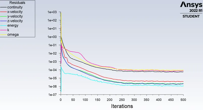
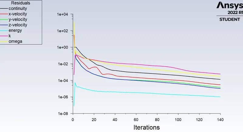
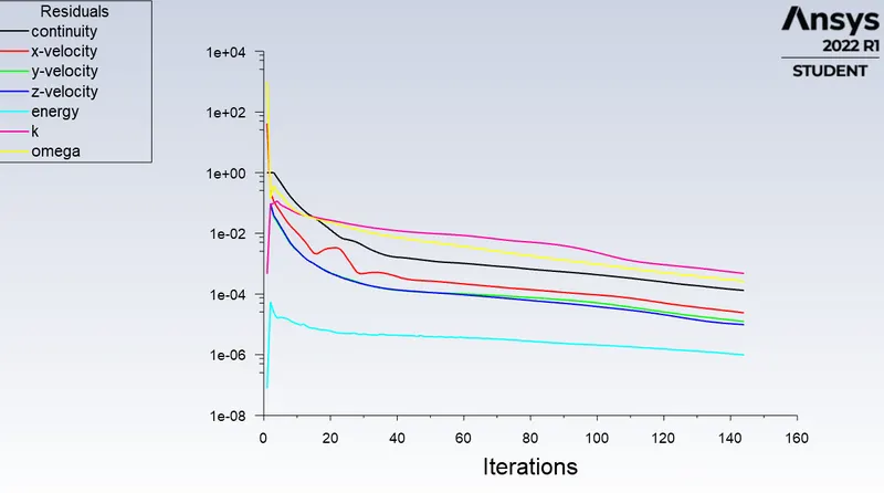
- Prove that the simulation has achieved convergence with appropriate images and plots.
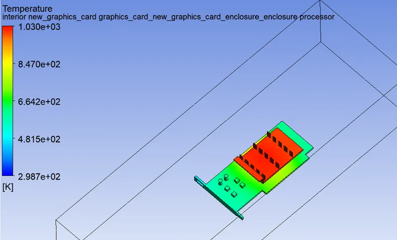
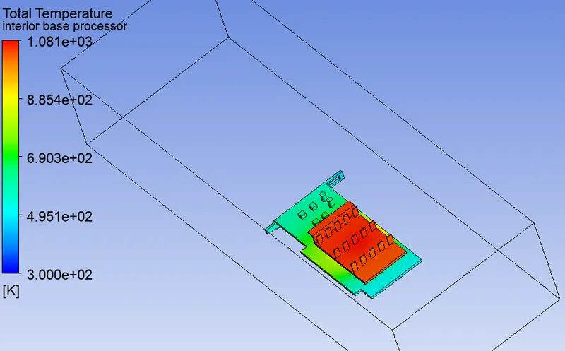
- Identify potential hotspots on the model.
Conjugate heat transfer:
Conjugate heat transfer is a type of heat transfer analysis between solids and fluid(s). This type of heat transfer includes both convection (between fluids) and conductive (between solids) heat transfer, as well as both forced and natural convection.
Graphics card:
A graphics card (also called a video card, display card, graphics adapter, GPU, VGA card/VGA, video adapter, or display adapter) is an expansion card which generates a feed of output images to a display device (such as a computer monitor).
Space claim geometry:
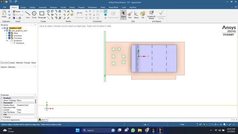
1.Base
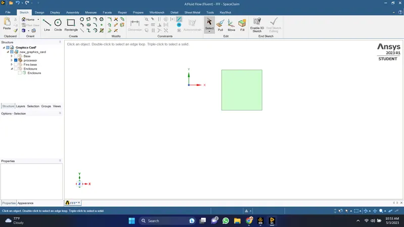
2.Processor
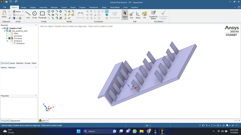
3.Fins:
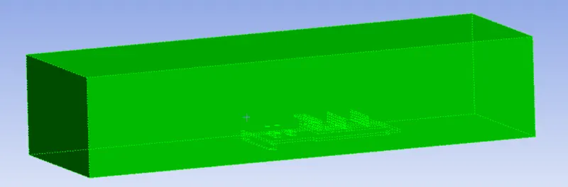
Enclosure:
Mesh:
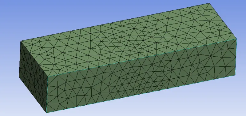
setup:
Use steady state pressure based solver and K-omega SSt model.
Turn the energy equation on.And create materials for different parts of the graphics card.
select the material
1. Fins: use copper as material for fins
2.Base: Use steel for Base.
3.Processor: Use silica for processor.
We need to change the materials in the cell zone conditions.
We use shell conduction and specify the source heat transfer coefficient,heat rate generation, no.of layers and layer thickness.
Then we initiale the solution with standard hybridisation for a time step of 0.1 and for 500 iterations and select the tempearture contour and create solution animation for the contour.
Case 1:
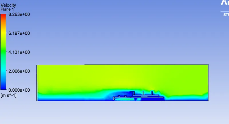
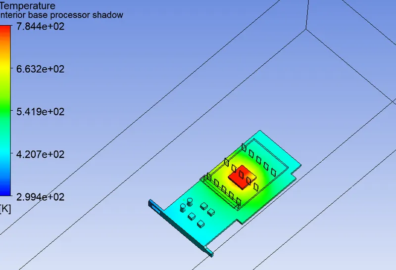
for base mesh , velocity = 5m/s ,no.of iterartions = 500 , step size =0.1
Residuals:
velocity contour:
Wall heat transfer coefficient:
Global hotspot temperature:
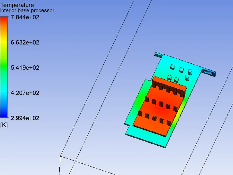
Hotspot region around procesor:
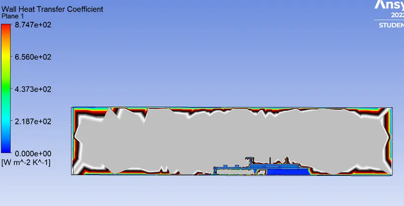
Case 2:
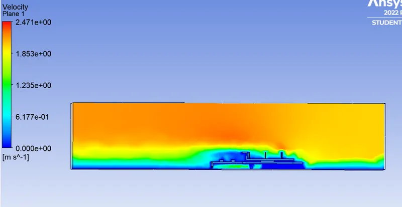
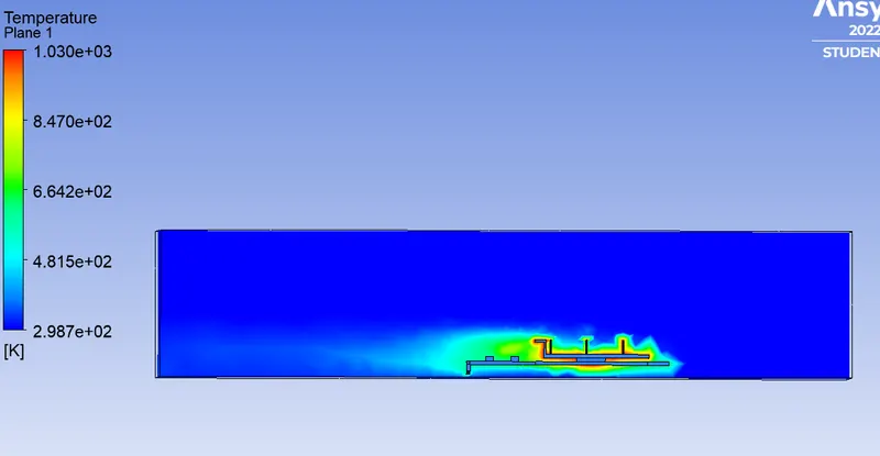
Base mesh velocity=2m/s , no.of iterartions = 500 , step size =0.1
Velocity contour:
Temperature contour on plane:
Wall heat transfer coefficient:
Global hotspot region:
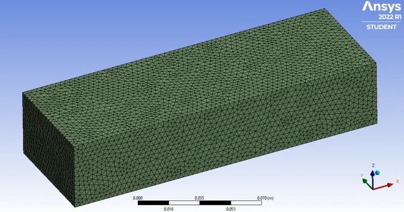
Refined Mesh:
We use element size = 0.003m
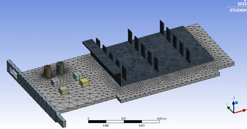
Body sizing of element size = 0.0005m for fins and the capture curve is turned on.
Body sizing of element size = 0.0005m for base and the capture curve is turned on.
Total no. of elements in refined mesh = 442307
Refined mesh:
Case 3:
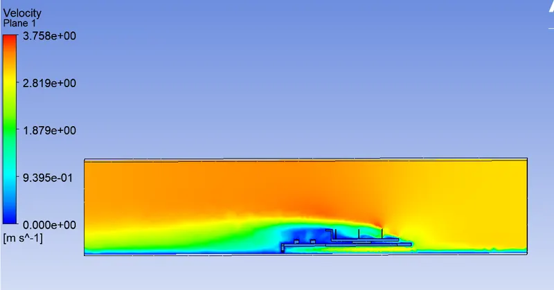
Refined mesh , velocity=3m/s, no.of iterartions = 500 , step size =0.1
Scaled residuals:
Velocity contour:
Wall heat transfer coefficient:
Global hotspot temperature:
Hotspot region around processor:
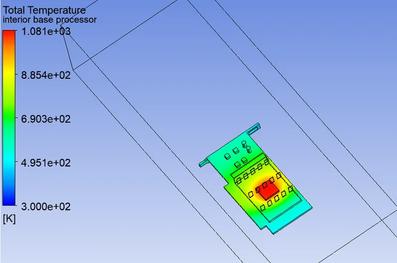
Case 4:
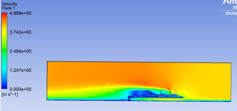
Refined mesh , velocity=4m/s,time step=0.1, no of iterartions =500
Residuals:
Velocity contour:
Wall heat transfer coefficient:
Global hotspot temperature:
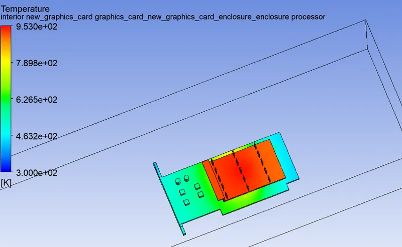
Hotspot region around processor.
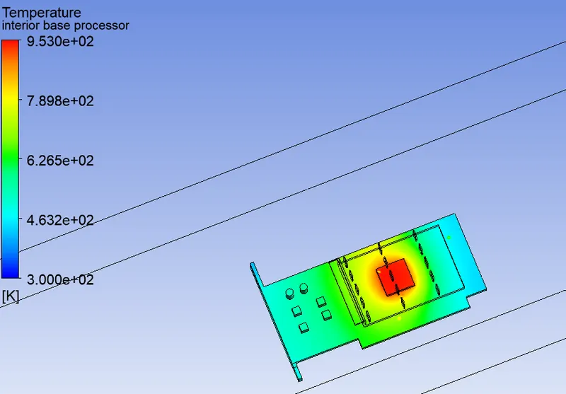
Results:
| Case | Mesh | Velocity | Heat transfer coefficient | Temperature |
| Case 1 | base mesh | 5m/s | 8.748e^+2 | 7.844e^+2 |
| Case 2 | base mesh | 2m/s | 8.747e^+2 | 1.030e^+3 |
| Case 3 | refined mesh | 4m/s | 8.431e^+2 | 1.081e^+3 |
| Caes 4 | refined mesh | 3m/s | 8.433e^+2 | 9.53e^+2 |
Conclusion:
1. As the number of elements increase we get accurate results of the themperature distribution.
2.From the above table ,we can see that the temperature of graphics card decreases with increse in inlet velocity.
3.Thus higher the inlet velocity better cooling and temperature distribution on the graphics card.