Week 4.2: Project - Transient simulation of flow over a throttle body
Aim:
Aim:-
- Set the transient-state simulation for flow over throttle body case setup in the converge.
- Export all the input files and run the simulation using Cygwin.
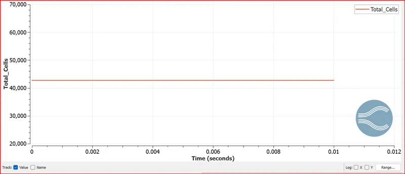
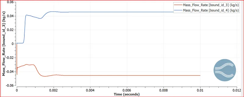
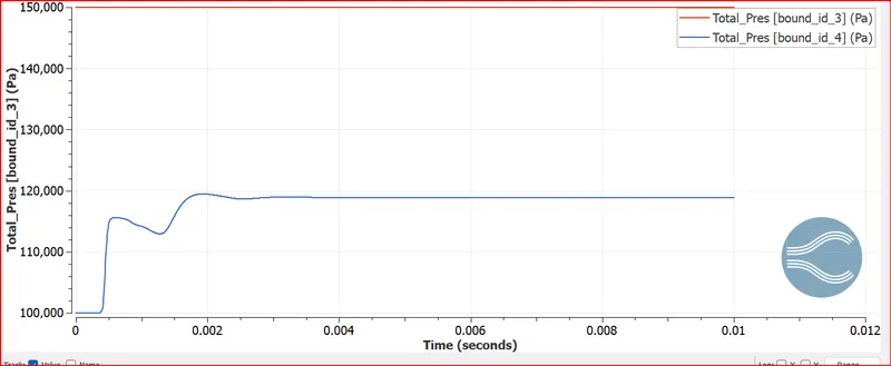
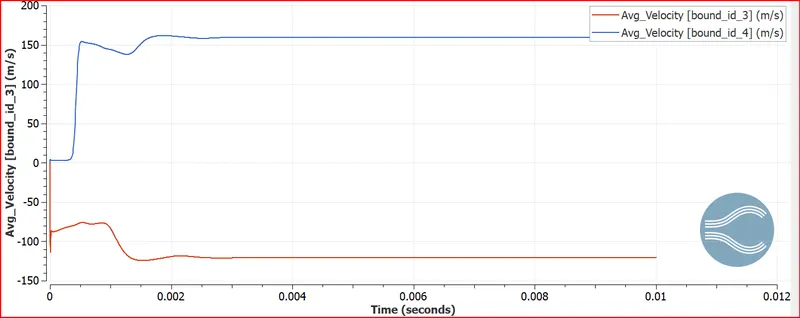
- Converge plot for velocity, pressure, mass flow rate, and total cell count.
- create animations of velocity and pressure contours plot for the flow inside the elbow pipe in which the throttle movement should be visible.
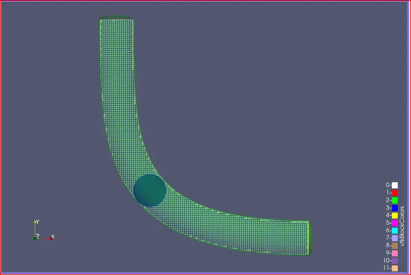
- Show mesh (i.e surface with edges) by creating a mid surface/slice along the z-direction.
- Explain the plots and write a detailed report on the project.
- Create another animation in Paraview representing streamline flow over throttle with transient state simulation.
Objective:-
- Import the throttle geometry model in the converge using the create option.
- Perform Geometry cleanup.
- Define the boundary to each surface of the geometry.
- Set normal direction on the inward side of the surfaces. means, define the direction towards the volume where the fluid is present.
- In case of setup define the material, simulation parameters, fluid region, boundary condition, no of cycles, grid definition.
- Extract the setup files in the simulation folder.
- Run exported input setup files in Cygwin.
- Post-process all the results into 3D outputs and open in Paraview.
- Show mesh generation on the 2D mid surface by using the slice command from the Paraview.
- Plot converge plot for velocity, pressure, mass flow rate, and total cell count.
- Create animations in the Paraview to show the changes in velocity and pressure contour with the throttle movement
- Create other animations to show the streamlines of the flow over the throttle body.
- Explain the plot animations and write a detailed report on the project.
Procedure:
Load the case setup file for steady state flow and make the following changes.
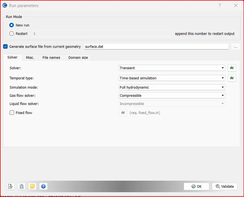
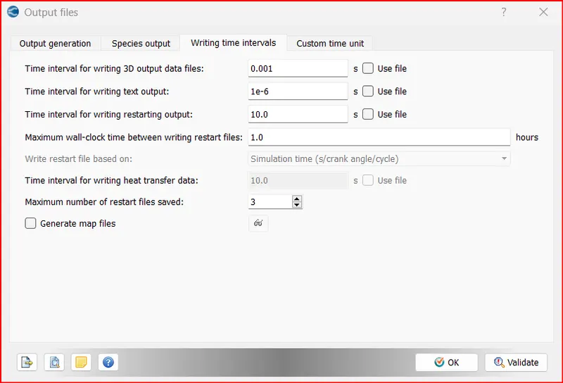
In run parameters select the transient solver
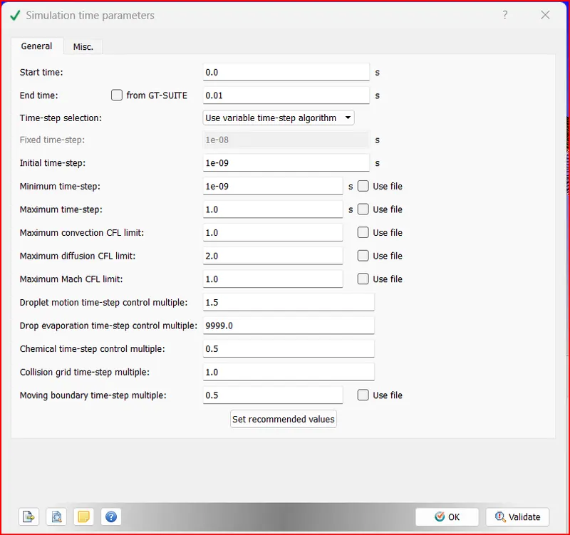
In Simulation time parameters, End time is 4*time for flow to take place through the pipe=4*vel*char length=0.01 secs.
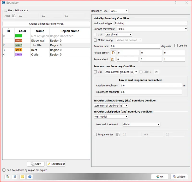
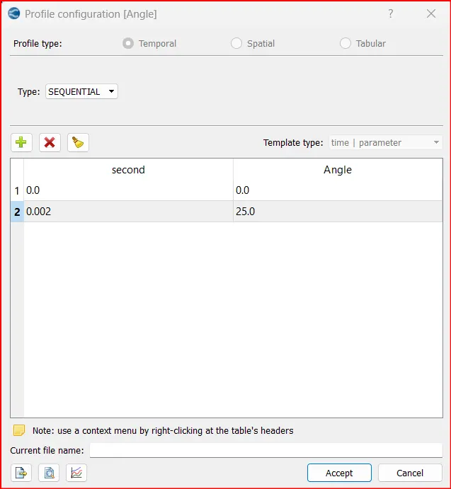
Now go to boundary and for throttle , Select boundary type as wall and wall motion type as rotating.
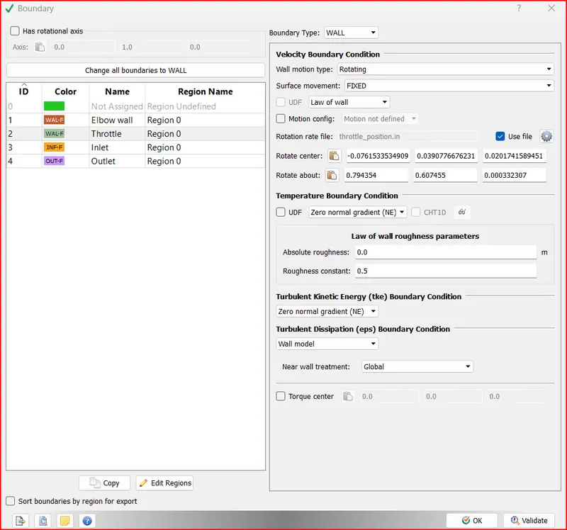
To get the centre point of the valve rotation,
Go to measure> Direction > Arc Normal select three points and click apply.

Copy the arc centre coordinates.
Contour plots:
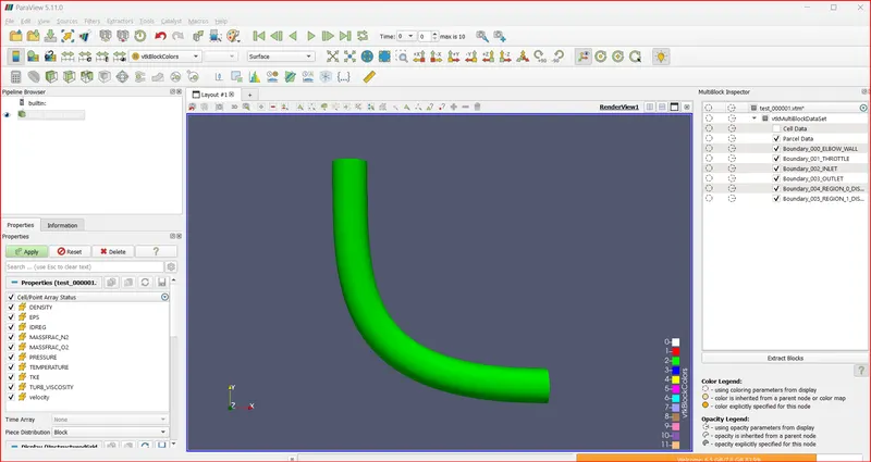
Open paraview and load.vtm file
In view> Multiblock Inspector > uncheck cell data.
Surface with edges
Plots:
Cell count
Mass Flow rate
pressure:
Velocity:
Procedure:
Load the case setup file for steady state flow and make the following changes.
In run parameters select the transient solver
In Simulation time parameters, End time is 4*time for flow to take place through the pipe=4*vel*char length=0.01 secs.
Now go to boundary and for throttle , Select boundary type as wall and wall motion type as rotating.
To get the centre point of the valve rotation,
Go to measure> Direction > Arc Normal select three points and click apply.
Copy the arc centre coordinates.
Contour plots:
Open paraview and load.vtm file
In view> Multiblock Inspector > uncheck cell data.
Surface with edges
Plots:
Cell count
Mass Flow rate
pressure:
Velocity: