Week 3 - External flow simulation over an Ahmed body.
AIM:
As the body is perfectly symmetric, we can run the simulation by considering the only half body. This is the best practice where you can save on the number of cells and get the results faster as well.
The geometry which is provided with the challenge needs a modification which you should be able to do at this stage of a course. You need to use the 'split body' command in SpaceClaim to perform the operation and then you can use the symmetry boundary condition in fluent to perform the simulation.
Run the simulation for the velocity of 25 m/sec with the default air properties in fluent.
For this challenge, you will have to provide answers to the following questions:
Q1. Describe Ahmed's body and its importance.
Q2. Explain the reason for the negative pressure in the wake region.
Q3. Explain the significance of the point of separation.
Expected Results:
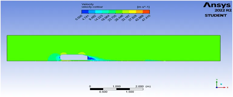
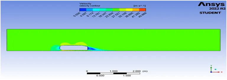
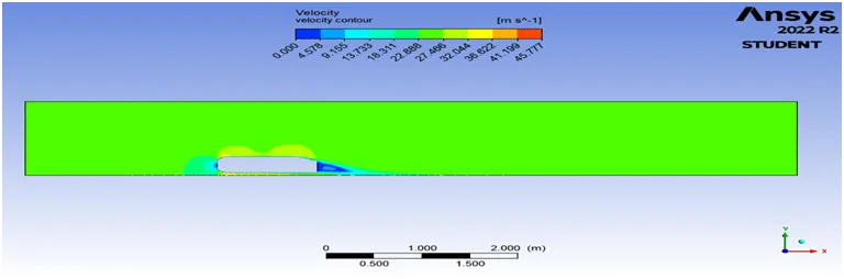
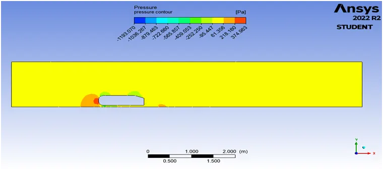
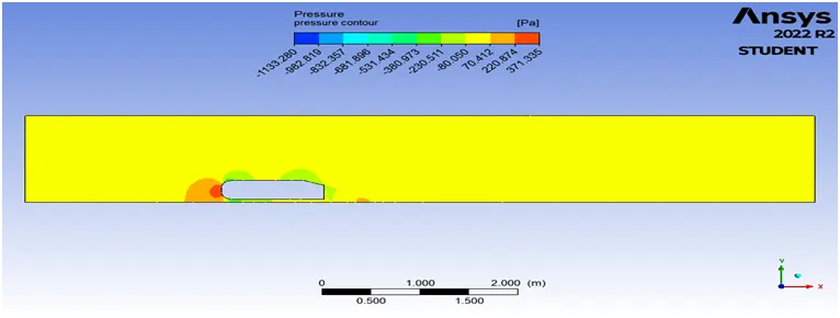
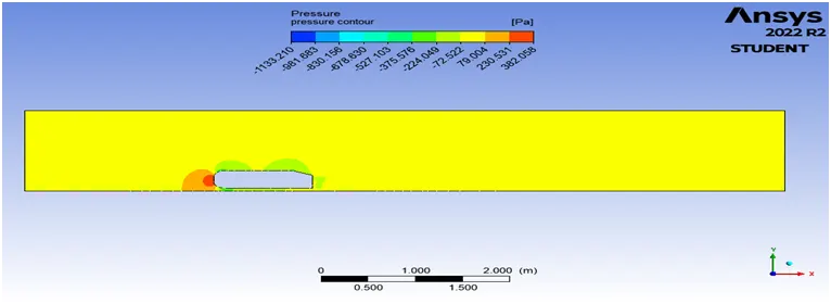
1. Velocity and pressure contours.
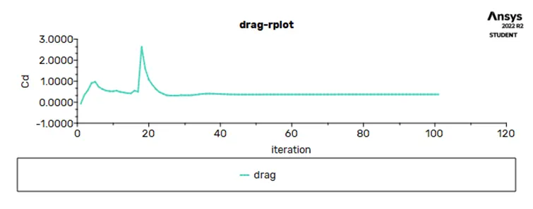
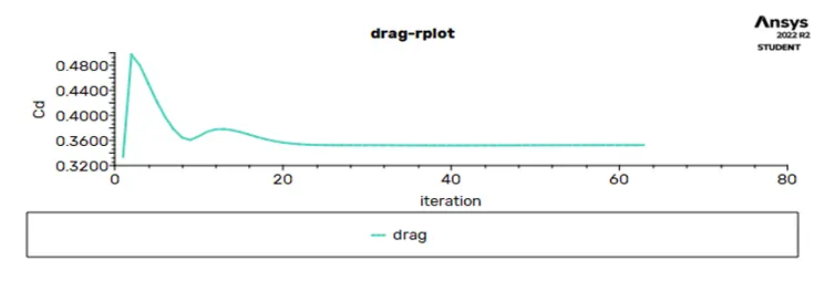
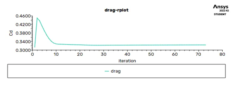
2. The drag coefficient plot for a refined case. ( For velocity of 25m/sec, the drag coefficient should be around 0.33).
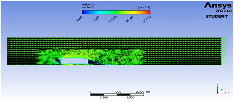
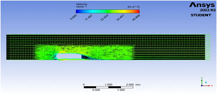
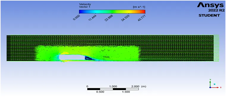
3. The vector plot clearly showing the wake region.
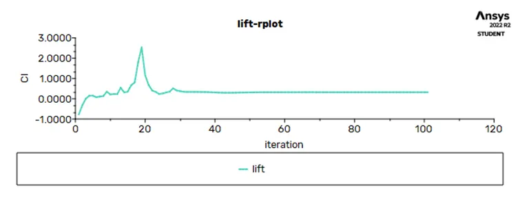
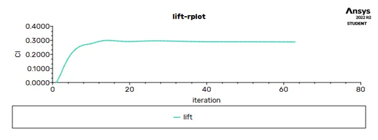
4. Perform the grid independency test and provide the values of drag and lift with each case.
Ahmed body :
- Ahmed body is a car model which uses to simulate the CFD results and validates with the actual results.
- The results like drag coe. , lift coe. , pressure, velocity etc. for different car models and compare these results with ahmed body results.
- Optimized external car aerodynamics is necessary to achieve efficient vehicles with minimized fuel consumption, CO2 emissions, and noise, while keeping a good driving stability. Steadily increasing computer power has been raising the importance of simulating the external aerodynamics of vehicles and computing the corresponding aerodynamic characteristic numbers. At present, an efficient resource management gains increased importance everywhere. A substantial part of the development time of cars is therefore invested in optimization. This is possible only and particularly by virtual development. In order to establish such development processes in the car industry, reliable simulation models validated by experiments are needed.
- Model experiments suitable for providing validation data make use of model bodies with geometries characterized by variable parameters, such as the slant angle at the back. One such body is the Ahmed body, a bluff model body of simple shape with basic aerodynamic properties of a vehicle, which has been used for many reference investigations.
The reason for the negative pressure in the wake region:
- As the high velocity fluid strikes on the frontal side of body due to this the velocity gets reduced and pressure increases. But as body moves the fluid is attached to the body and it moves forward. But when the fluid leaves the body due to sudden change in dimensions or sharp corners the flow separation occurs and behind the body there is low velocity region creates and this region is called as wake region.
- In this region the eddies are formed and due to these eddies a vacuum creates. It means the negative pressure creates. It means there is no fluid element present. Due to absent of fluid molecules in wake region some negative pressure creates.
- Due to this negative pressure some pulling force observes in wake region. Also we experience a lift force.
- Also this wake region there is more turbulence occurs due abrupt changes.
- As the velocity increases the point of separation moves left side and the wake region area reduces but still there is negative pressure or vacuum remains.
- We can clearly understand this concept further by looking contour plots.
significance of the point of separation.
- The location of a separation point depends upon various factors such as Reynolds number, the surface roughness, the level of fluctuation in the free stream. And it is usually difficult to predict exactly where the separation will occurs unless there are sharp corners or abrupt changes in the shape of the solid surface.
- The point of separation generally occurs at sharp corners. The importance of this point is that the wake region area depends upon this point. As the Reynolds number or velocity of fluid over a body increases the point of separation moves towards left side i.e. in opposite direction of wake region creates and distributed area of wake region reduces.
Geometry cleanup :
- Open workbench.
- Drag fluid flow(fluent) to the project scheme.
- Firstly import the cad file to the geometry.
- Then right click on geometry -> edit geometry in discovery
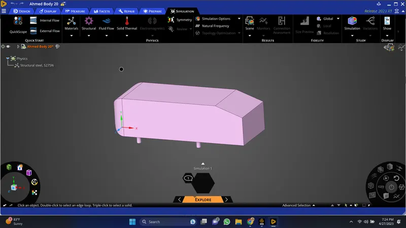
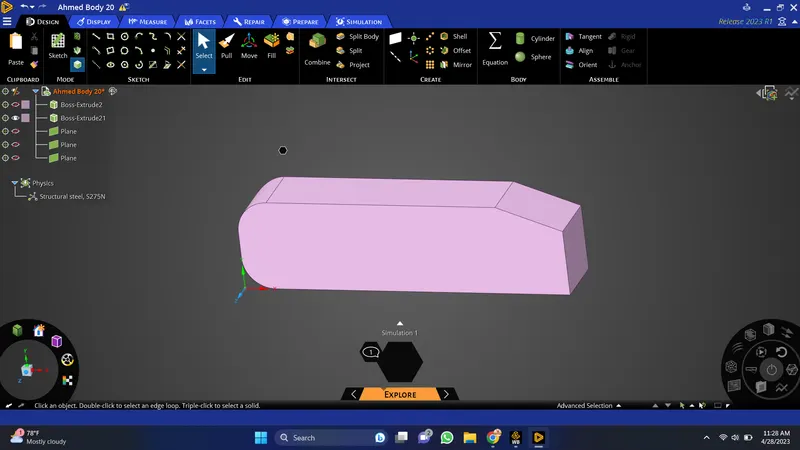
- Now, this is the symmetric car model. so lets delete the half portion of a body. For that first of all creates plane and use split body tool under design to split the body along the plane. Then hide the planes.
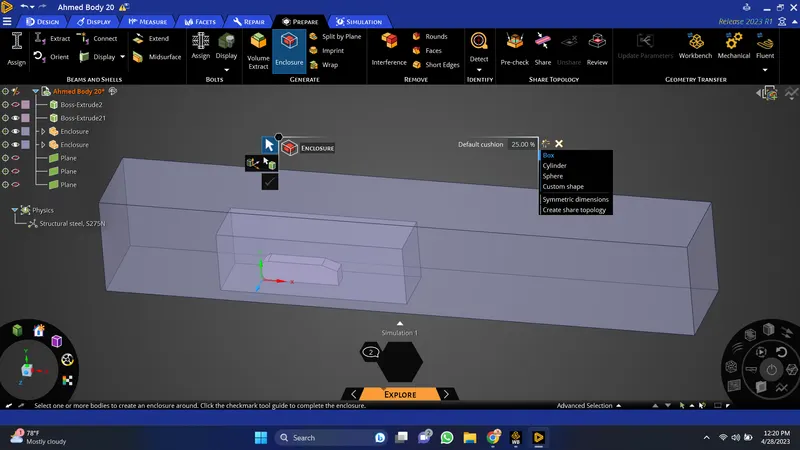
- Now, lets create the fluid domain around this car model. For that we are creating 2 enclosures with standard dimensions. To create enclosure goto prepare -> enclosure -> select body -> uncheck symmetric dimensions under outline -> give appropriate dimensions. -> click on green tick.
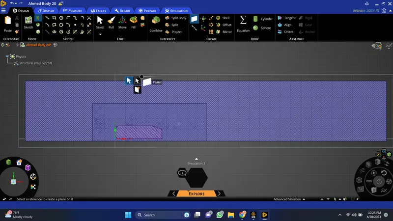
Now the some common area is represented by looking hatches which are overlaps. So delete this common area by using interference tool under prepare
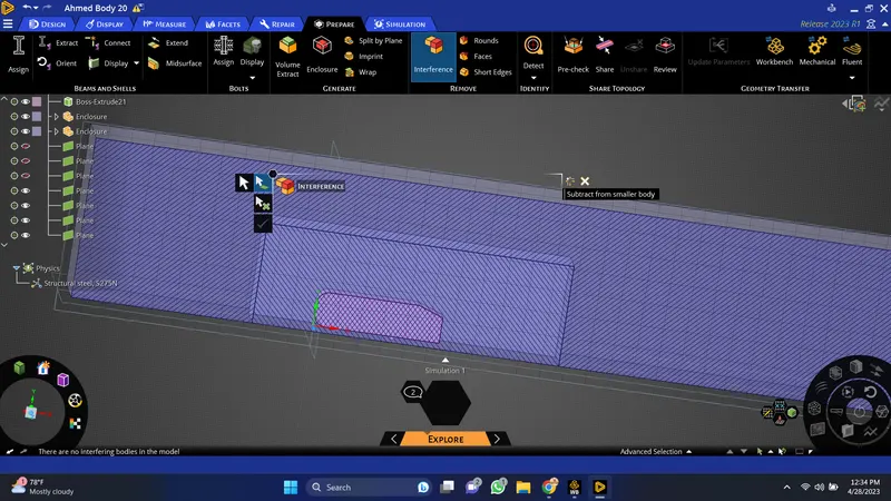
Now this common area has been removed.
Meshing:
-
- Open mesh.
- Select the faces and gives the name as shown below
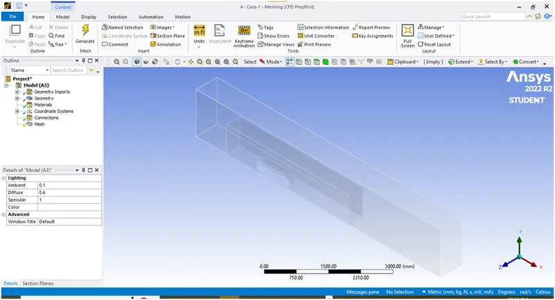
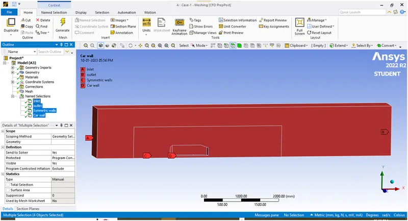
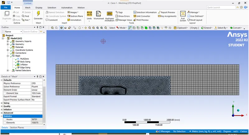
Now we will create the course mesh on outside enclosure and fine mesh on inner enclosure.Here we are doing mesh independent study to finalize the mesh size by comparing the results for different sizes.Lets create the multizone mesh for outer enclosure.Then create face meshing for inner enclosure.Then creates an inflation layer around the car wall to capture the viscous effects near the wall.
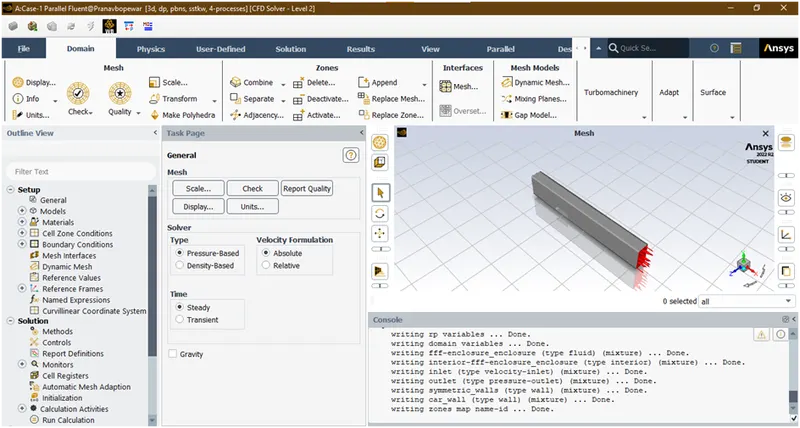
|
Pressure based |
|
Inlet- V=25m/s |
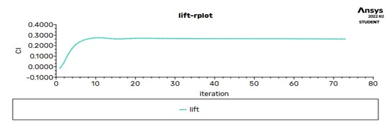
- Now creates 2 new report definitions as drag and lift.
- Initialize the solution
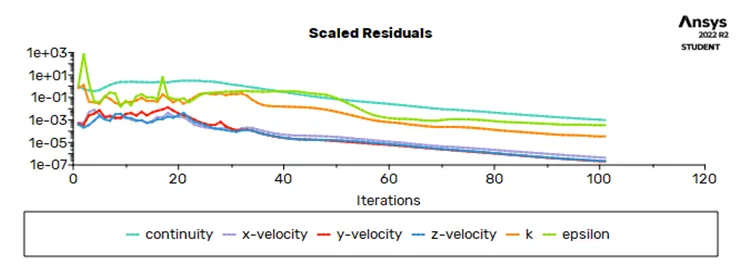
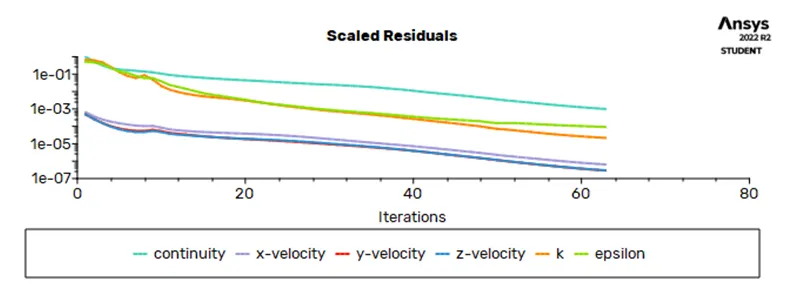
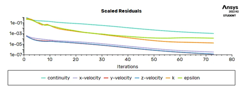
- Run the simulation for some 300 iterations.
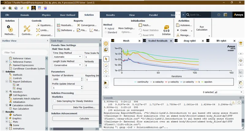
Now solution has been converged.
- Now saved the residual,drag,lift plots.
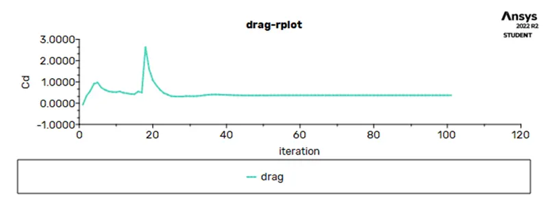
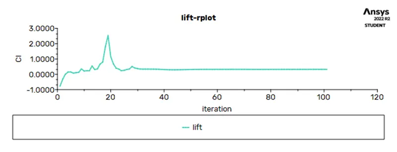
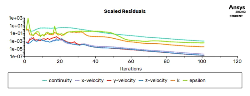
- Now open the cfd-post and plots a velocity, pressure contour plots and also velocity vector plots. And saved these plots. For that firstly create the xy-plane and then creates the contours.
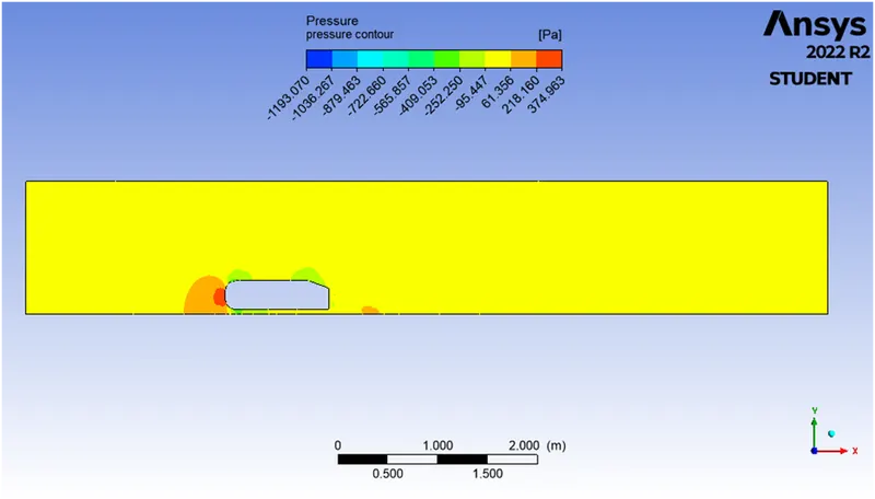
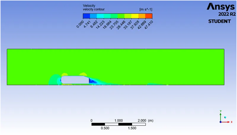
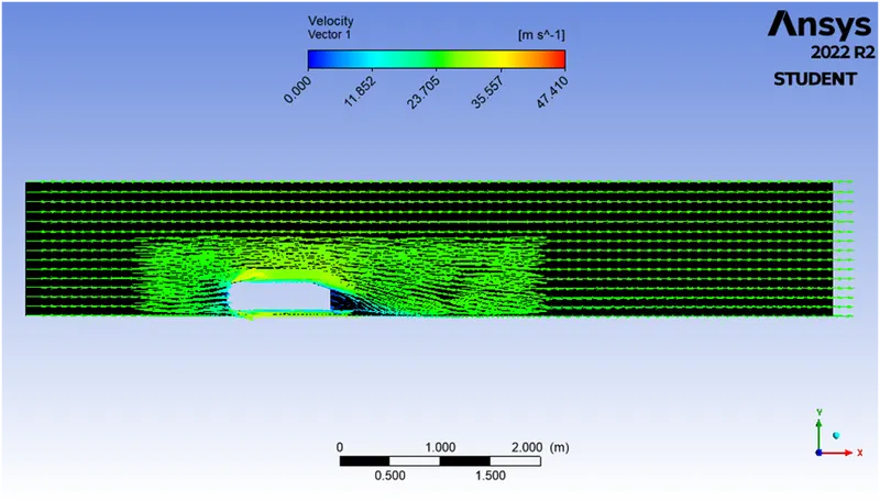
- Residual plots
|
Cases |
Plots |
|
1 |
 |
|
2 |
 |
|
3 |
 |
- Drag plots
|
Cases |
Plots |
|
1 |
 |
|
2 |
 |
|
3 |
 |
- Lift plots
|
Cases |
Plots |
|
1 |
 |
|
2 |
 |
|
3 |
 |
- Velocity contour plots
|
Cases |
Plots |
|
1 |
 |
|
2 |
 |
|
3 |
 |
- Pressure contour plots
|
Cases |
Plots |
|
1 |
 |
|
2 |
 |
|
3 |
 |
- Velocity vector plots
|
Cases |
Plots |
|
1 |
 |
|
2 |
 |
|
3 |
 |
Conclusion:
Mesh become finer when we increase the cell counts and formation of wake region become clearer which in turn help us to get more accurate result.