Week 8 - Challenge 3 - Coin Holder Design
AIM
TO Create the Coin Holder Plastic component through the given Class-A surface. To begin with, the tooling axis for the given Class-A Surface should be created meeting the requirements of the draft angle and at the end perform the Draft analysis on the model. Take the Thickness of the component to be 2.5 mm
INTRODUCTION:
CLASS-A SURFACE: a surface made by the designer which is given as an input to the plastic modeler to work on. It is aesthetic surface and the outer most surface.
CLASS-B SURFACE: a surface below a certain thickness from the class-A surface is class-B surface. This is the surface that contains engineering aspects of a model.
CLASS-C SURFACE: a surface that joins class-A and class-B surfaces is class-C surface.
MATERIAL CHOOSED BY: (ABS)- for Acrylonitrile Butadiene Styrene. ABS is an impact-resistant engineering thermoplastic & amorphous polymer. ABS is made up of three monomers: acrylonitrile, butadiene and styrene:
- Acrylonitrile: It is a synthetic monomer produced from propylene and ammonia. This component contributes to ABS chemical resistance & heat stability
- Butadiene: It is produced as a by-product of ethylene production from steam crackers. This component delivers toughness & impact strength to ABS polymer
- Styrene: It is manufactured by dehydrogenation of ethyl benzene. It provides rigidity & processability to ABS plastic
ABS Processing Conditions
Acrylonitrile-butadiene Styrene (ABS) has a broad processing window and can be processed on most standard machinery.
Injection Molding
- Pre-drying is not always needed for injection molding with a vented cylinder. In case drying is needed then 4 hours at 80°C is generally sufficient. Signs of moisture are stripes, streaks or bubbles in the molding and if any of these are seen then the material should be pre-dried
- Melt temperature: 210-270°C
- Mold temperature: of 40-70°C
- Material Injection Pressure: 50 - 100 MPa
- Injection Speed: Moderate - High
Extrusion
- Pre-Drying: 3 hours at 70-80°C
- Extrusion temperature: 210 to 240°C
- Screw Design: L/D ratio of 25-30 is recommended
METHODOLOGY:
In this model we have focused on the following things:
Tooling axis
Draft analysis
Class-B surface
Class-C surface
Making a solid model from surface.
Following tools were used to reach the final step:
Extract
Multi Extract
Un-trim
Trim
Extrapolate
Offset
Edge fillet
Boundary
Sweep
Join
Close (part design)
STEP :1
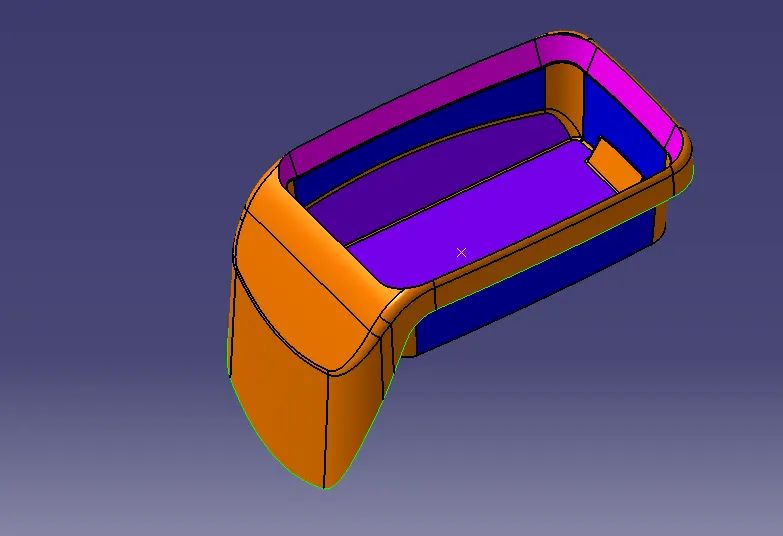
- To save the part in IGS -> CATpart.
- Then the class A surface is checked for the connectivity of the surface and ensure it is completely joined and there will be no gap between the surfaces.
- If it is not join together make it with a minimum tolerance of 0.001 to 0.003 and check for connectivity of the surface.
- Connectivity of the surface can be done by two ways by join method and by boundary method.
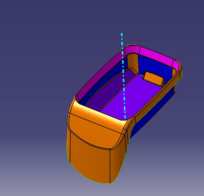
- Split the surfaces into multiple profiles then Identify the surface where it is not possible to create a tooling axis and check on which direction is best fit for tooling axis and then define the tooling axis and draft direction.
- Here for defining the tooling axis first we have created a point at middle of the base surface and create an axis with respect to that point then define the tooling axis using the intersect method by creating a bisecting line.
- Then do a draft analysis on the class A surface and identify the draft angle then give the nominal value for the draft
STEP :2
- The direction in which the mould open and closes is called the tooling axis direction.
- Check the connectivity of the surface and ensure there will be no gap between the surfaces and then define the tooling axis.
- While creating a tooling axis please ensure to give the tooling axis on a flat length surface or the surface which have a hole on it.
- Create a point on the middle of the base surface by using point on the surface command then create a intersection for the surface and extract the reference lines which will be helpful for creating the dummy tooling axis using the intersect method by creating a bisecting line..
- Use the line command and draw the lines which is aligned with the extracted lines and extended it to the required length.
STEP :3
B SURFACE
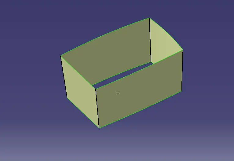
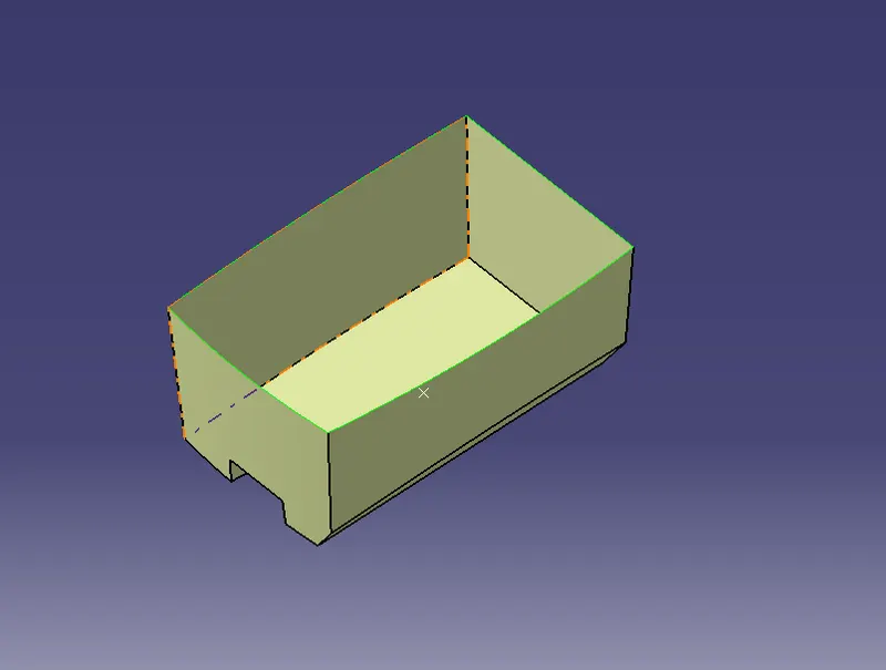
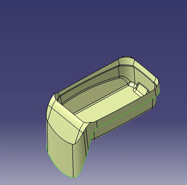
- In the case of Class A the surface below is called core and the surface above is called cavity.
- Class A is an aesthetics surface and class B is an engineering surface.
- B surface should be inside the class A surface.
- B surface can be divided into four surfaces the side walls, top walls, outer flange and the base surface and later trim them altogether.
- First step is to create the side wall surfaces by extracting the required surface from Class A and untrimmed it thus we will get a single surface which will be extrapolated to get the required size and finally offset it to the inner side of class A as per the thickness of the material and trim them together and apply the required fillet by measuring the values from class A.
- Base surface of the component is then extract, untrimmed, extrapolated, offset and trimmed.
- The top walls can be directly extrapolated from the
- extracted surfaces and offset it for the required size of the material.
- Then join the base, side wall and top wall by trim operations.
- As the Outer flange is surface complex it can be divided into two parts and extract them then go for extrapolation, offset, split and join operations and finally check the for the connectivity by intersecting method.
- Fillet is applied to the required surfaces by measuring the fillet value from the class A surface and added the value in fillet of 2.5mm thickness of (A >C) value
- Now all the four geometries are trimmed together to get the B surface.
STEP :4
C SURFACE
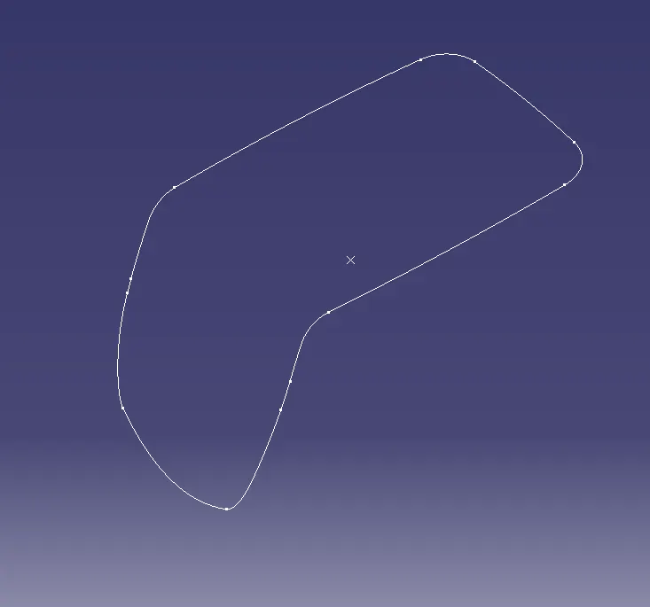
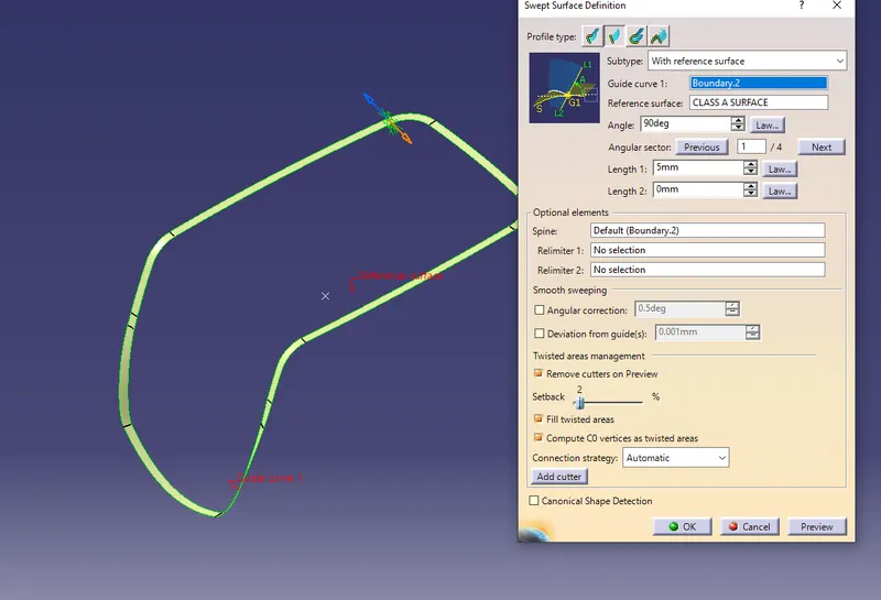
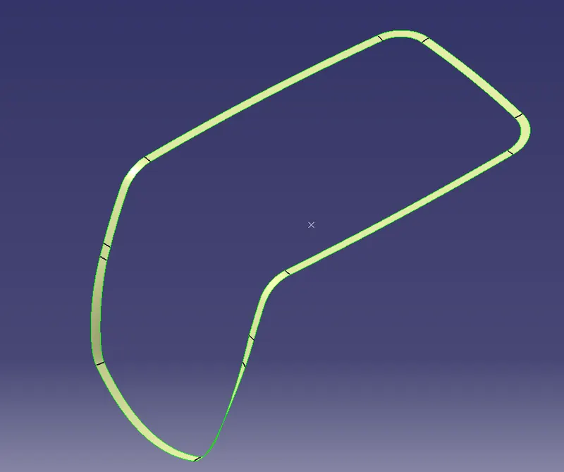
- C surface has been created from the boundary lines of class A surface and by extracting the supporting surfaces then sweep the boundary lines with reference to the extracted surfaces.
- In order to get the C surface first we have to create a boundary lines of class A surface or by using multiple extrapolated command and check for the continuity of it.
- Create a sweep with reference to the curve and the reference surface with a 90 degree angle and give the inside direction Check for the continuity of the surfaces if there is any gap go for extrapolated and trim all together now we will get the class C surface.
STEP :5
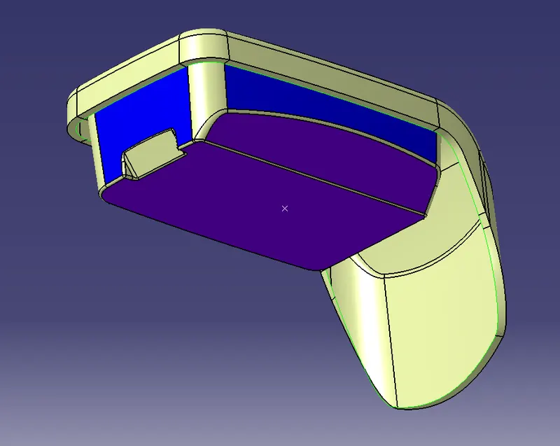
- join surface A and C
- Then join the class A surface and C surfaces together by join command then check it for connectivity of the surfaces .
STEP :6
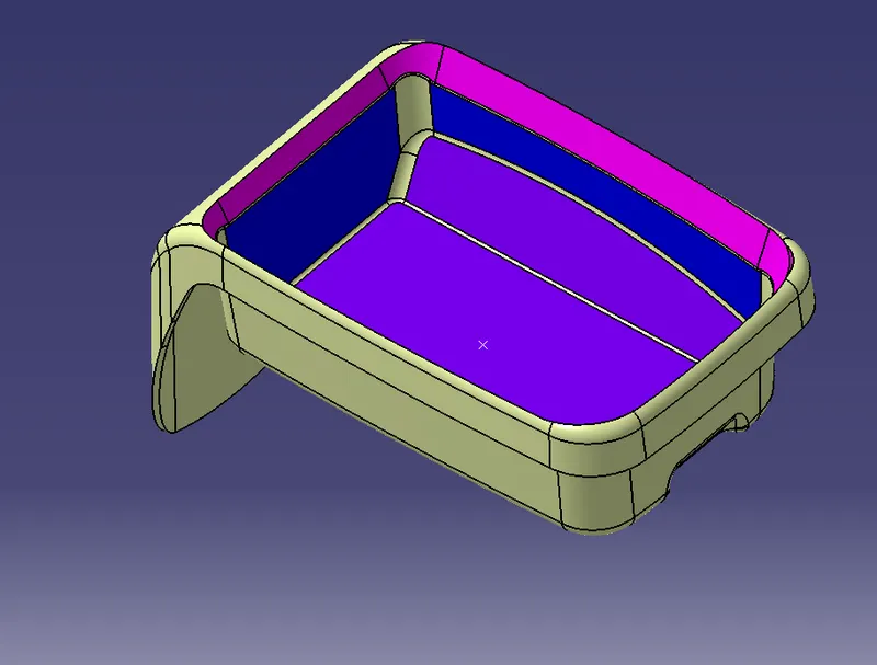
- Then Unhide the surface B trimmed it with B surface we will get the final component again check whether the final body is closed by using boundary command.
STEP :7
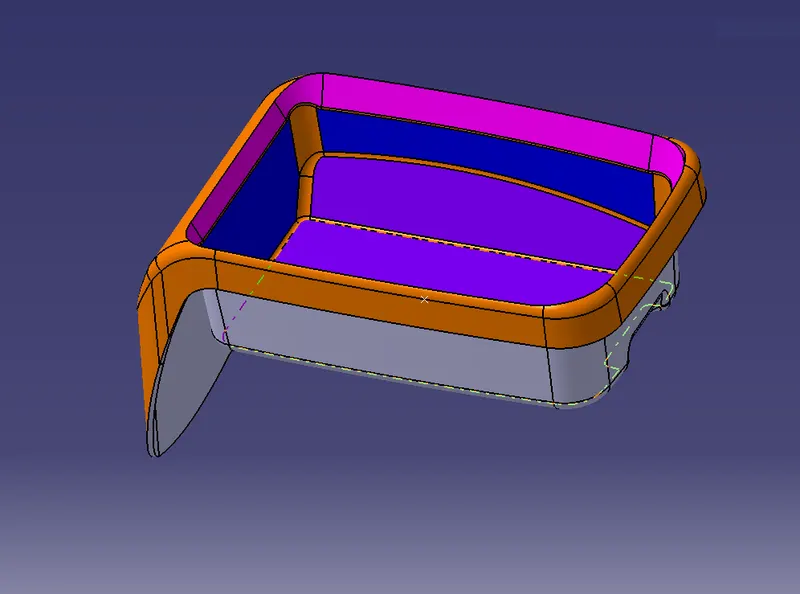
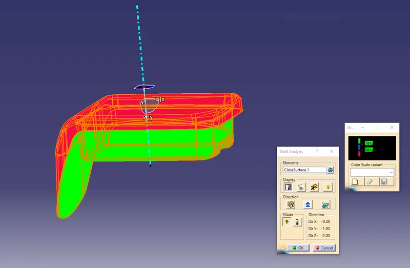
- Closed solid body is created by using the close surface on part workbench by selecting the final Trimmed component and do the draft analysis for the same
Draft analysis
- Draft allows for the component to release from the mould, most parts or applications require a minimum of 0.5 to 1 degree draft angle and 3 dgree draft angle is widely used as per the norm.
- Change the material mode to customize mode before moving to the draft analysis.
- Insert –analysis-feature draft analysis
- Defining the draft direction Select draft analysis from the tool bar and click on the compass symbol and pull the compass from the right side top corner of the workbench and place it on the component where want to do the draft analysis. ‘W’ of the compass and tooling axis should be aligned on the same line.
- Once the compass is aligned with the tooling axis click on the lock symbol and drag on the surface we will get a wrong mark then select that point a table will appear it shows the draft value on the table we can adjust the draft value and analysis it for all the edges and surfaces.
- By clicking the on the surface and using the flipping tool we can assign the Flipping direction, the color of the surface change as per the flipping direction .
- Analysis under running point and move the mouse on the surface and it will show the details of the surface deg direct at each and every point of the surface.
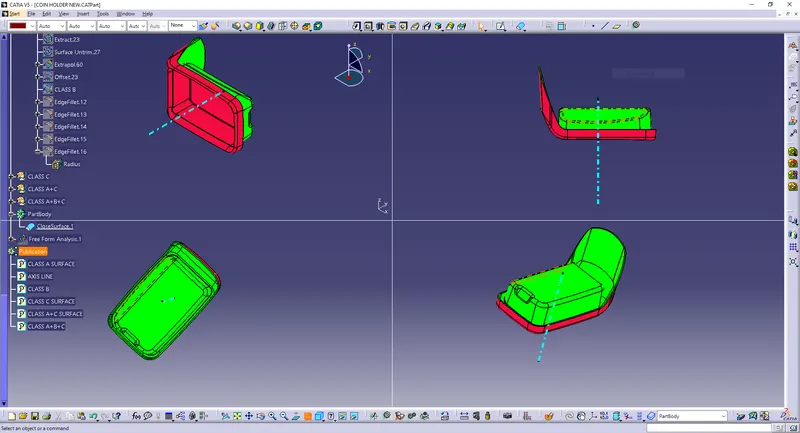
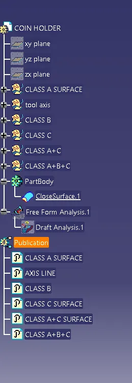
DESIGN TREE: