Week 8 - Challenge 1 - Draft Analysis on a Fan Cover
WEEK 8 CHALLENGE 1
DRAFT ANALYSIS OF A FAN COVER
AIM
- To create the tooling axis for the given fan cover model meeting the requirements of the draft angle.
- To perform draft analysis on the model.
THEORY
With plastic injection molding, it is important to design for manufacturability. To do this, every step of the process must be taken into consideration. A draft angle will help avoid most of these issues.
A draft angle is a slant that is applied to each side of most features of an injection molded part. The angle, which is positioned to run toward the direction of a mold’s pull and parting line, helps with releasing the part from the mold.
When developing parts for plastic injection molding, applying draft (or a taper) to the faces of the part is critical to improving the moldability of the part. Without it, parts run the risk of poor cosmetic finishes, and may bend, break, or warp due to molding stresses caused by the plastic cooling. Equally important, an absence of draft may prevent parts from ejecting from the mold, damaging not only the parts, but possibly the mold itself.
Draft analysis is a method of checking the draft angle on various faces of a part with a particular direction. Designers of plastic parts and mold tooling manufacturers can use the Draft Analysis tool to check the correct application of draft to the faces of their part. With draft analysis, they can verify draft angles, examine angle changes within a face, as well as locate parting lines, injection, and ejection surfaces in parts.
TOOLS USED
- Point
- Point - Direction Line
- Point - Point Line
- Intersect
- Bisecting Line
- Axis System
- Publication
- Feature Draft Analysis
PROCEDURE
Creating the Tooling Axis
- Open the given CATPART file.
- Check for gaps on the surface using Join command.
- Find an approximate tooling axis by observing the surface.
- Create an axis system at the centre of the fan cover.
- Create an intersect between the surface and the ZX plane.
- Create point-point lines on the two lines on the intersect which could interfere with the tooling axis.
- Create a bisecting line for the above created lines to create a tooling axis for the ZX plane in the X direction.
- Create an intersect between the surface and the XY plane.
- Create point-point lines on the two lines on the intersect which could interfere with the tooling axis.
- Create a bisecting line for the above created lines to create a tooling axis for the XY plane in the Y direction.
- Create a bisecting line for the two tooling axes created above. This is the tooling axis for the surface.
- Make the toling axis thicker for easier observation.
Publication
- Go to Tools > Publication... and select the tooling axis and the class A surface.
- This creates a Publication tree structure which can be used to easily access the class A surface and the tooling axis.
Draft Analysis
- Go to Customised View Parameters. Ensure Material shading is enabled under the mesh section.
- Go to Insert > Analysis > Feature Draft Analysis.
- Use the compass to define the draft direction.
- Change the draft angle to 3 degrees in the colour scale.
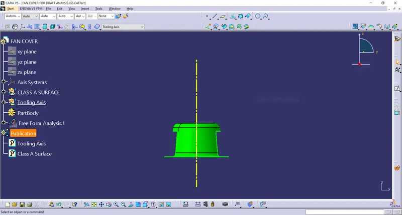
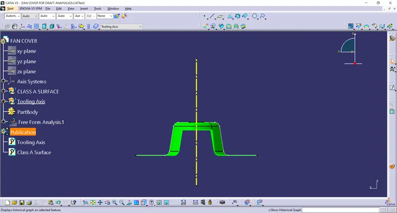
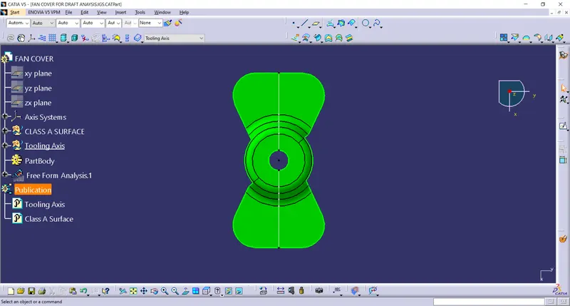
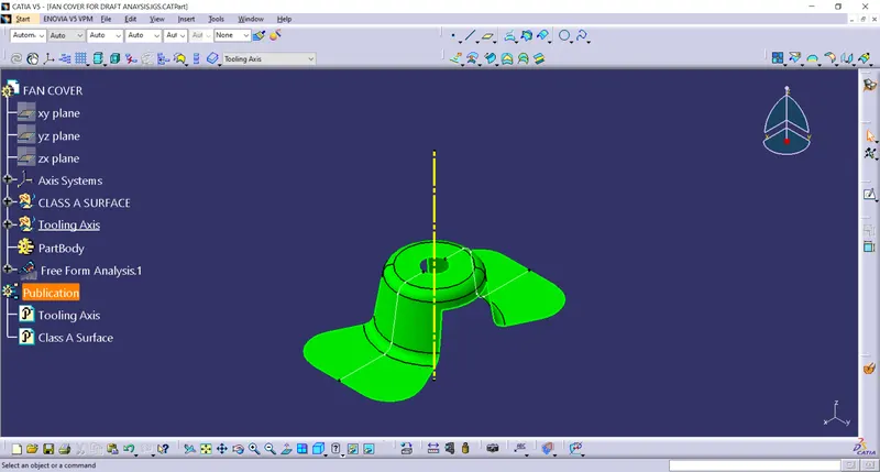
- If the component passes the draft analysis, it will be in green.
- Choose the running point option to check the draft angles at individual points.
PART IMAGES OF DRAFT ANALYSIS
- Front View :
- Side View :
- Top View :
- Isometric View :
CONCLUSION
- Tooling axis created for the given fan cover model meeting the requirements of the draft angle.
- Draft analysis performed on the model.
- Model cleared the draft analysis.