Design, Modelling, Assembly and Rendering of an American Chopper
DESIGNING, MODELLING, ASSEMBLY AND PHOTO-REALISTIC RENDERING OF AN AMERICAN CHOPPER
OBJECTIVES
- To design and create models of the parts of an American Chopper using
- To assemble the parts modeled for the American Chopper using
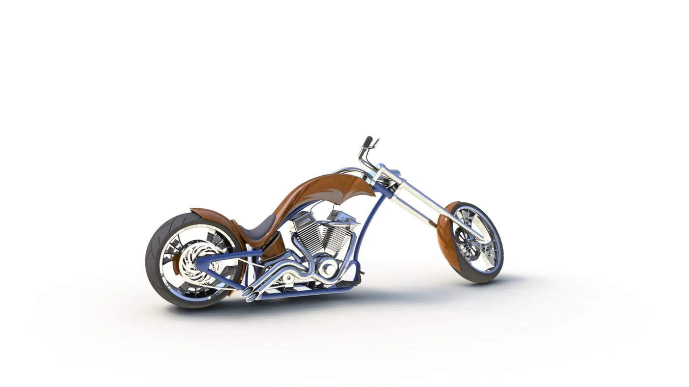
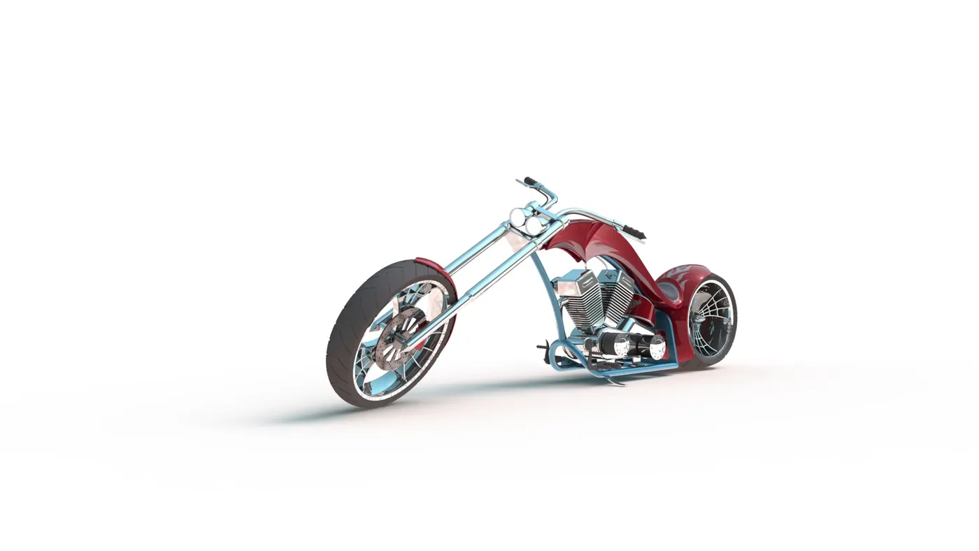
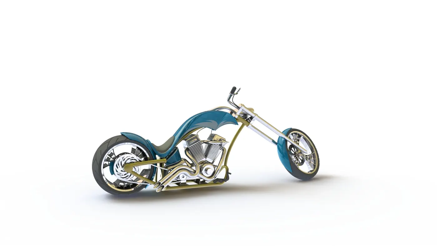
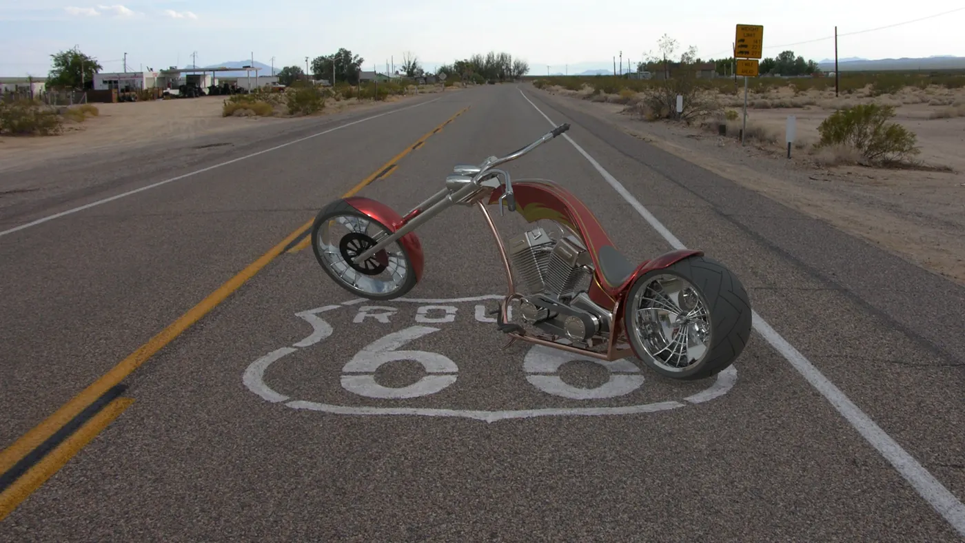
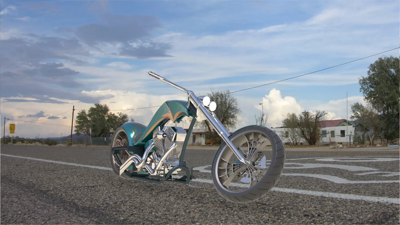
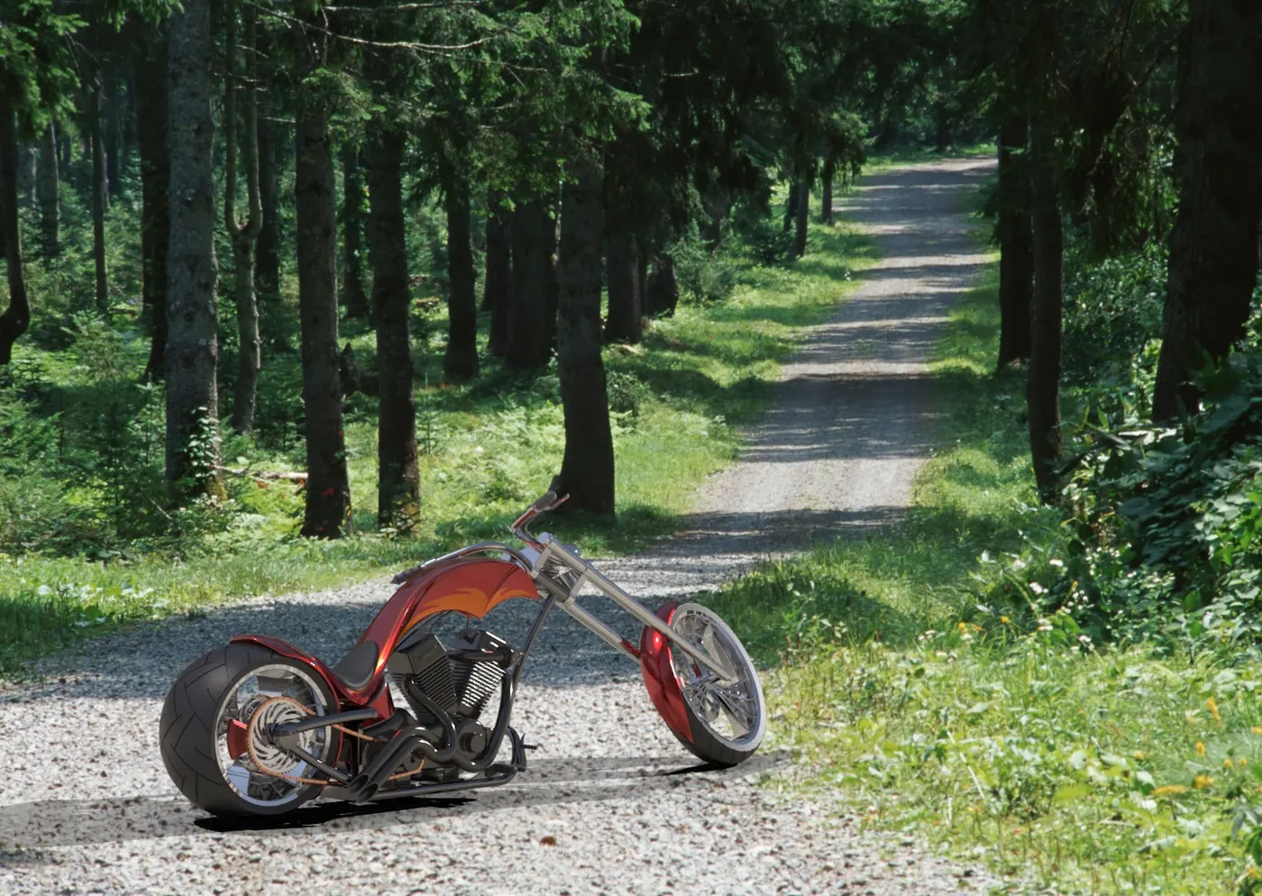
- To create a photo-realistic rendering of the American Chopper using Solidworks Photoview 360and Solidworks Visualize.
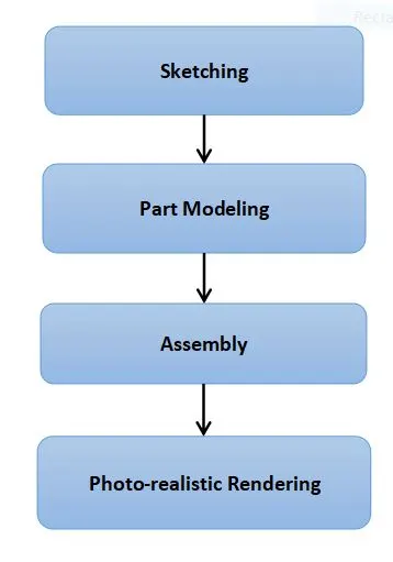
DESIGN METHODOLOGY
PARTS MODELED
- Transmission Belt
- Kick Stand
- Front Fender
- Rear Fender
- Chain
- Oil Tank
- Pedal
- Front Wheel
- Rear Wheel
- Front Fork
- Chassis
- Engine
- Gas Tank
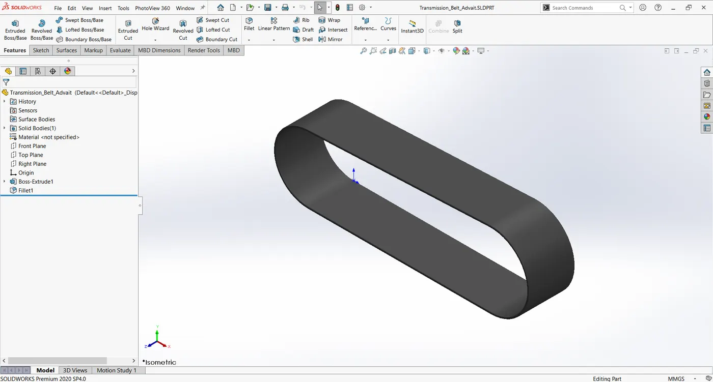
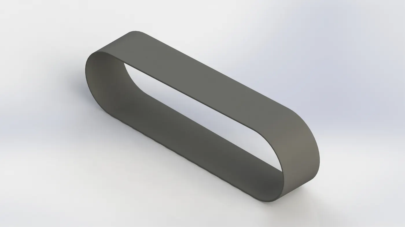
i) Transmission Belt
Transmission belt transfers power from the engine to the gearbox.
Features used:
- Sketch: Two dimensional drawings of the model to be created with respect to a plane of view.
- Offset: Creates an offset sketch at a specified distance.
- Extruded Boss: Creates three dimensional models from two dimensional
- Fillet: Creates a rounded edge on a part.
- Appearance: Gives a part the appearance of the material it is made of, or of custom paints and decals.
ii) Kickstand
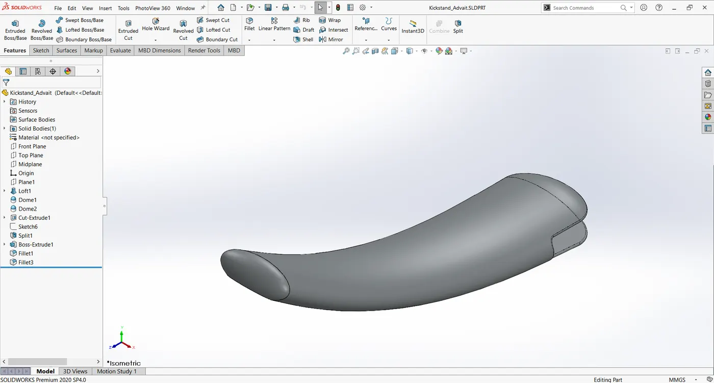
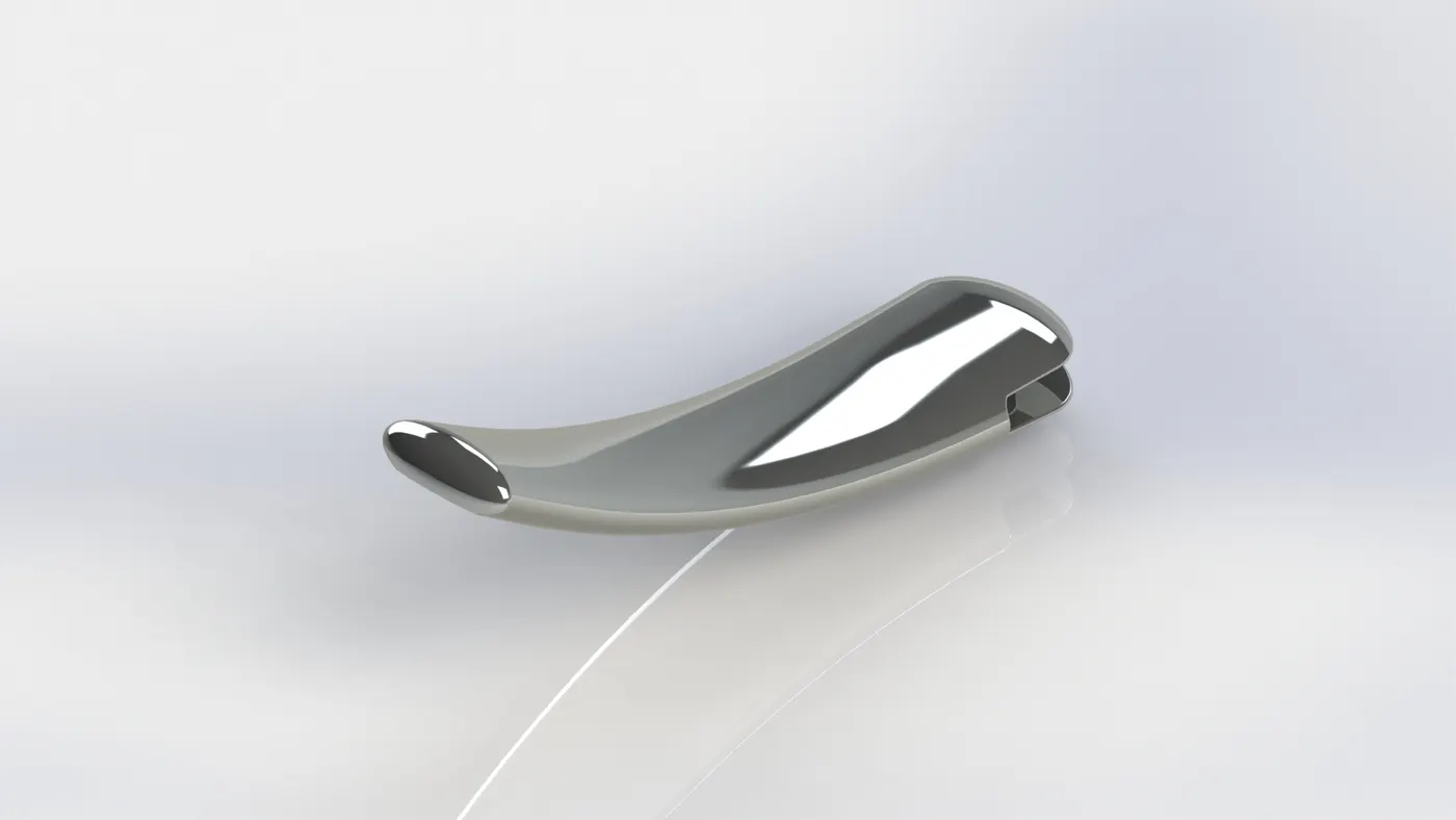
Kickstand is used to support the chopper on the ground.
Features used:
- Sketch
- Lofted Boss: Creates parts with variable cross section along a given These cross sections are linearly blended from one section to the other.
- Dome: Creates a dome over a place surface.
- Extruded Boss
- Extruded Cut: Removes material from a solid according to shapes given by a two dimensional sketch. It is the opposite of Extrude Boss.
- Fillet
- Split: Creates multiple parts from an existing part.
- Appearance
iii) Front Fender
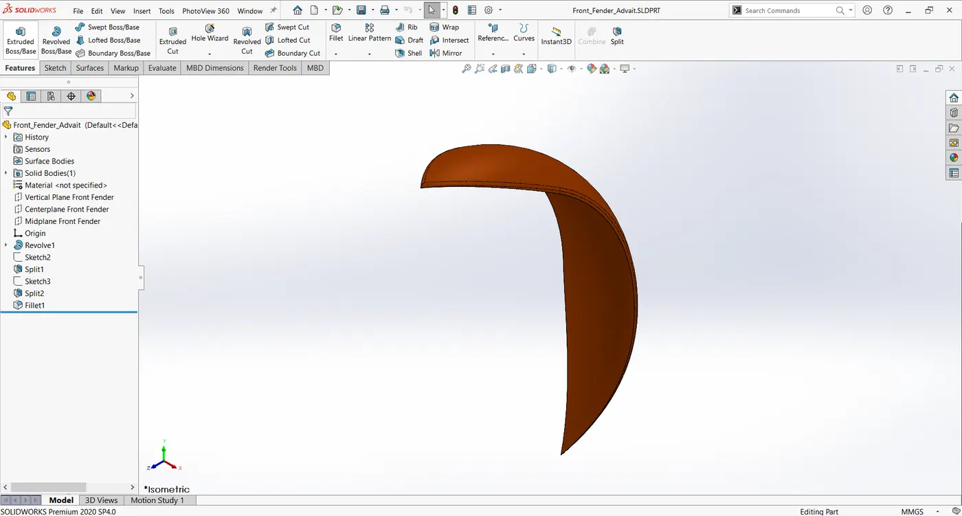
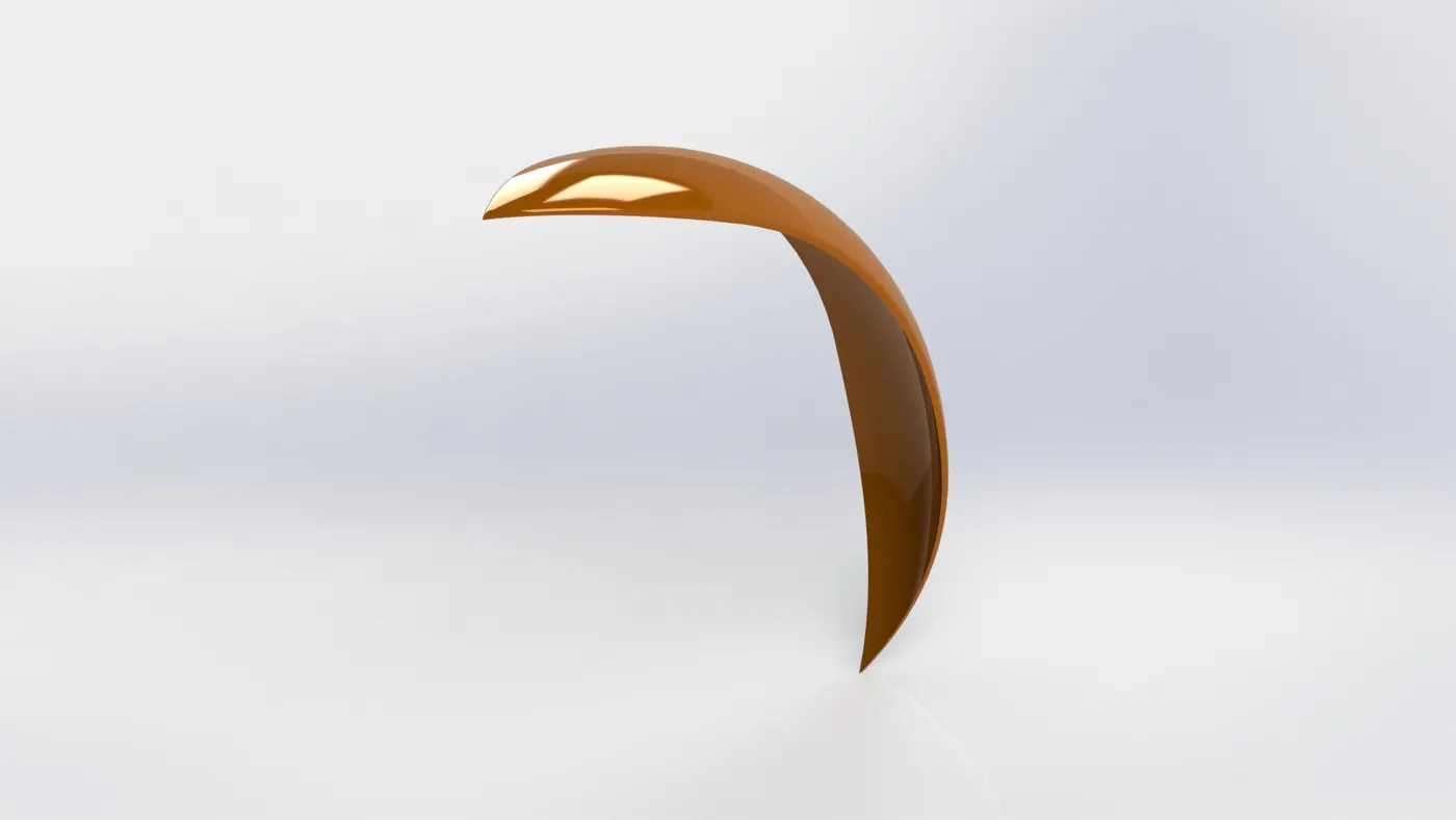
Front fender is placed above the front wheel to prevent debris and other materials from the road and the wheel from hitting the rider or other parts of the chopper.
Features used:
- Sketch
- Offset Entities
- Trim Entities: Trims or extends sections of a sketch.
- Revolved Boss: Creates axi-symmetric three dimensional parts from
- Dynamic Mirror: Mirrors selected entities across a plane
- Split
- Appearance
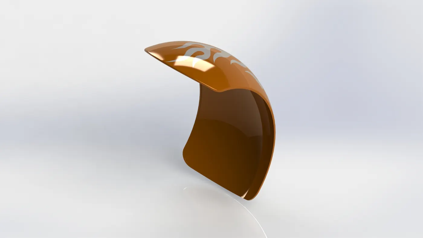
iv) Rear Fender
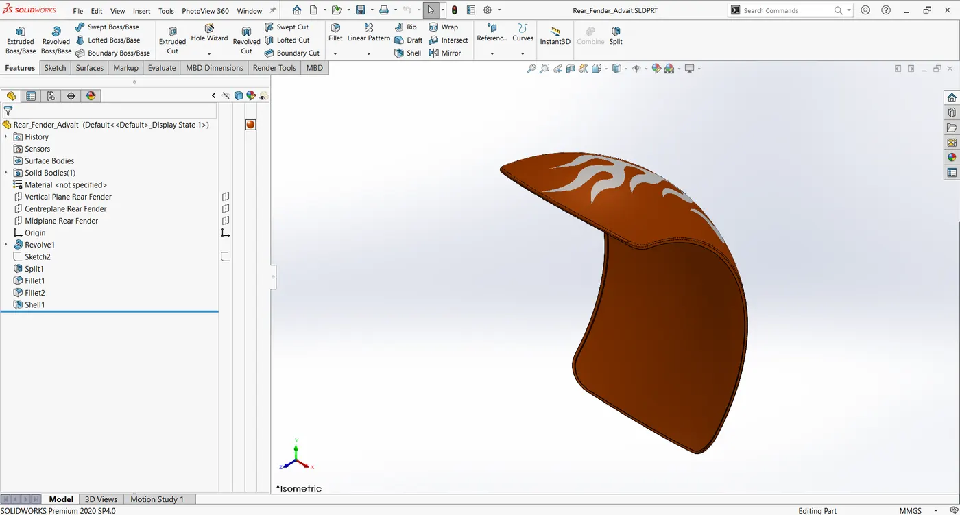
Similar to the front fender, the rear fender above the rear wheel protects the rider and the chopper from debris from the wheels.
Features used:
- Sketch
- Offset Entities
- Trim Entities
- Revolve
- Dynamic Mirror
- Split
- Appearance
- Decals: Adds decals and other such designs to the part
v) Oil Tank
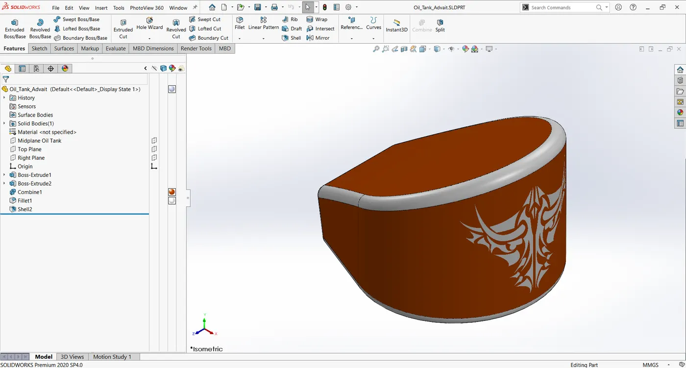
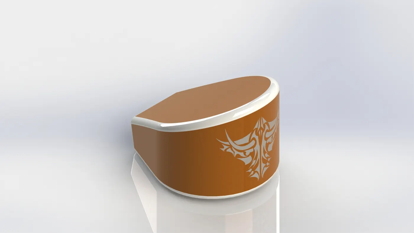
Oil for the engine is stored in the oil tank. It is a hollow tank with 3mm thickness.
Features used:
- Sketch
- Extruded Boss
- Combine: Used to combine multiple bodies to form a single body.
- Fillet
- Shell: Used to create a hollow material out of a solid part with a specified
- Appearance
- Decals
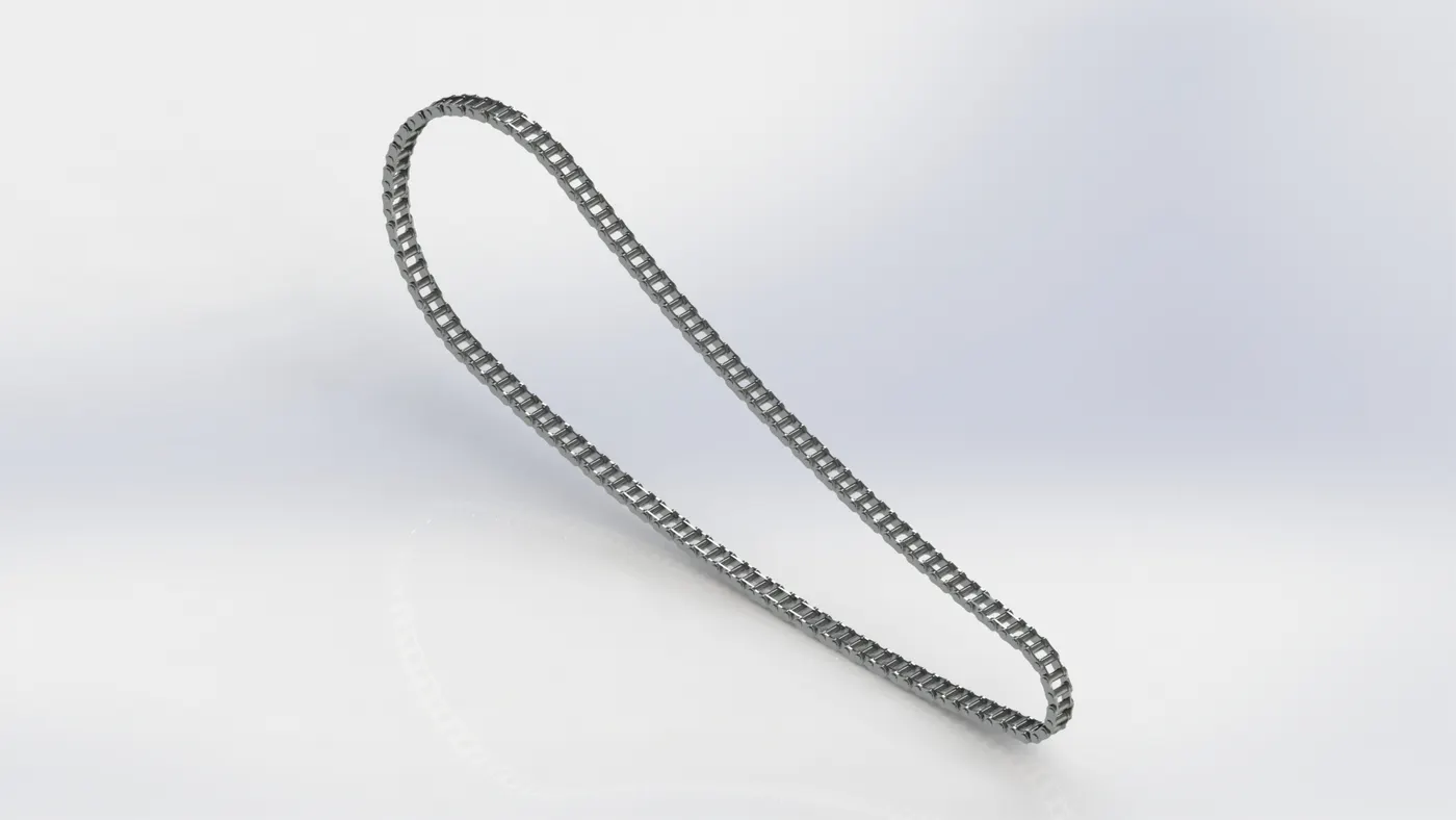
vi) Chain
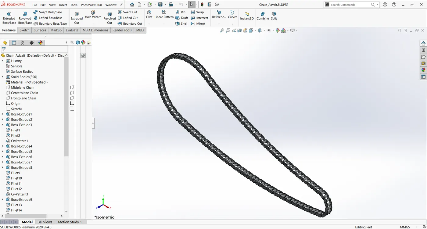
Chain is used to transmit power from the engine to the sprocket on the rear wheel. It is made of plates and pins.
Features used
- Sketch
- Trim Entities
- Fillet
- Block: Sketch entities can be saved as blocks so that they can be reused easily multiple times in other sketches.
- Extruded Boss
- Pattern: Parts can be repeatedly constructed as arrays along linear or curved sketches. It can be linear, circular or curve driven.
- Appearance
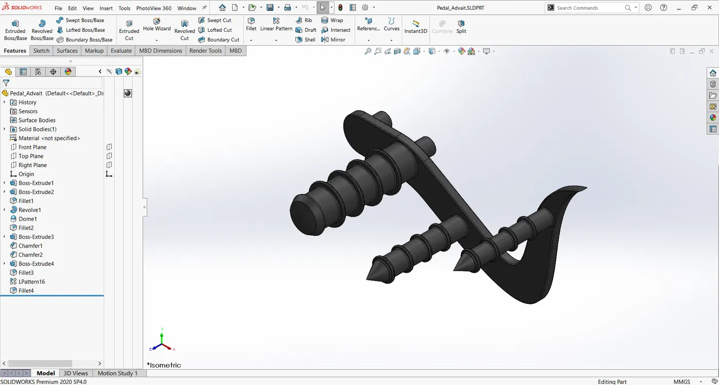
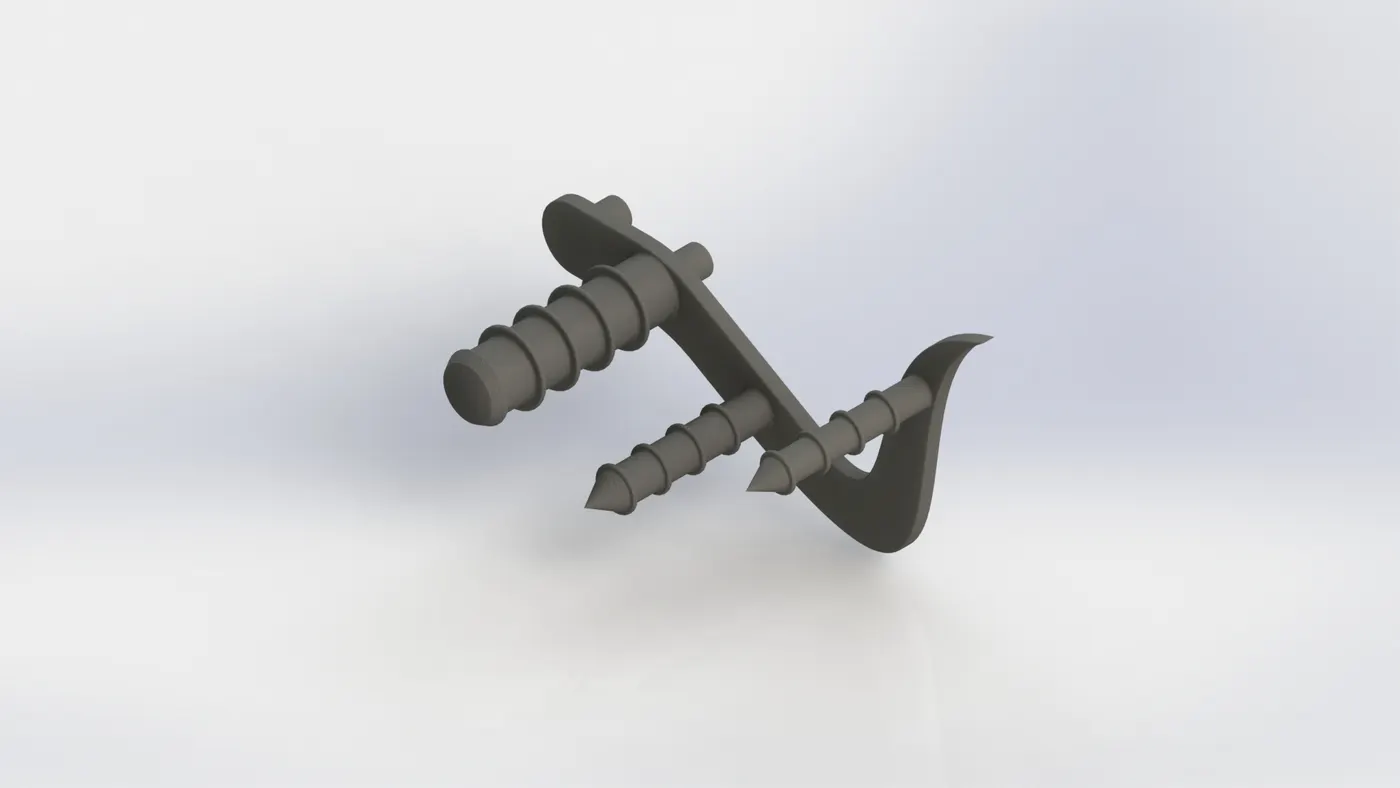
vii) Pedal
Pedal is used to support the legs of the rider.
Features used:
- Sketch
- Extruded Boss
- Fillet
- Linear Pattern
- Dome
- Chamfer: A chamfer is an angled slope that’s added along edges to make them less sharp.
- Appearance
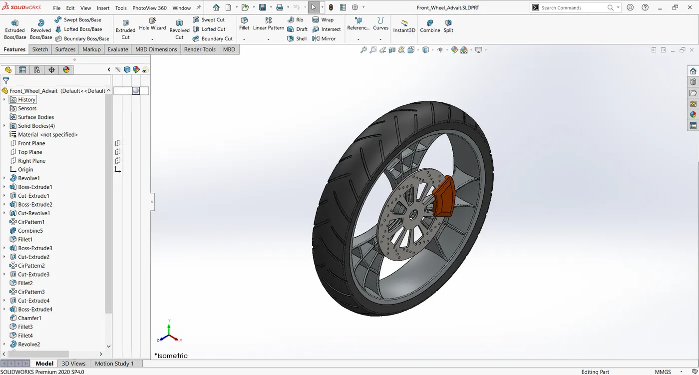
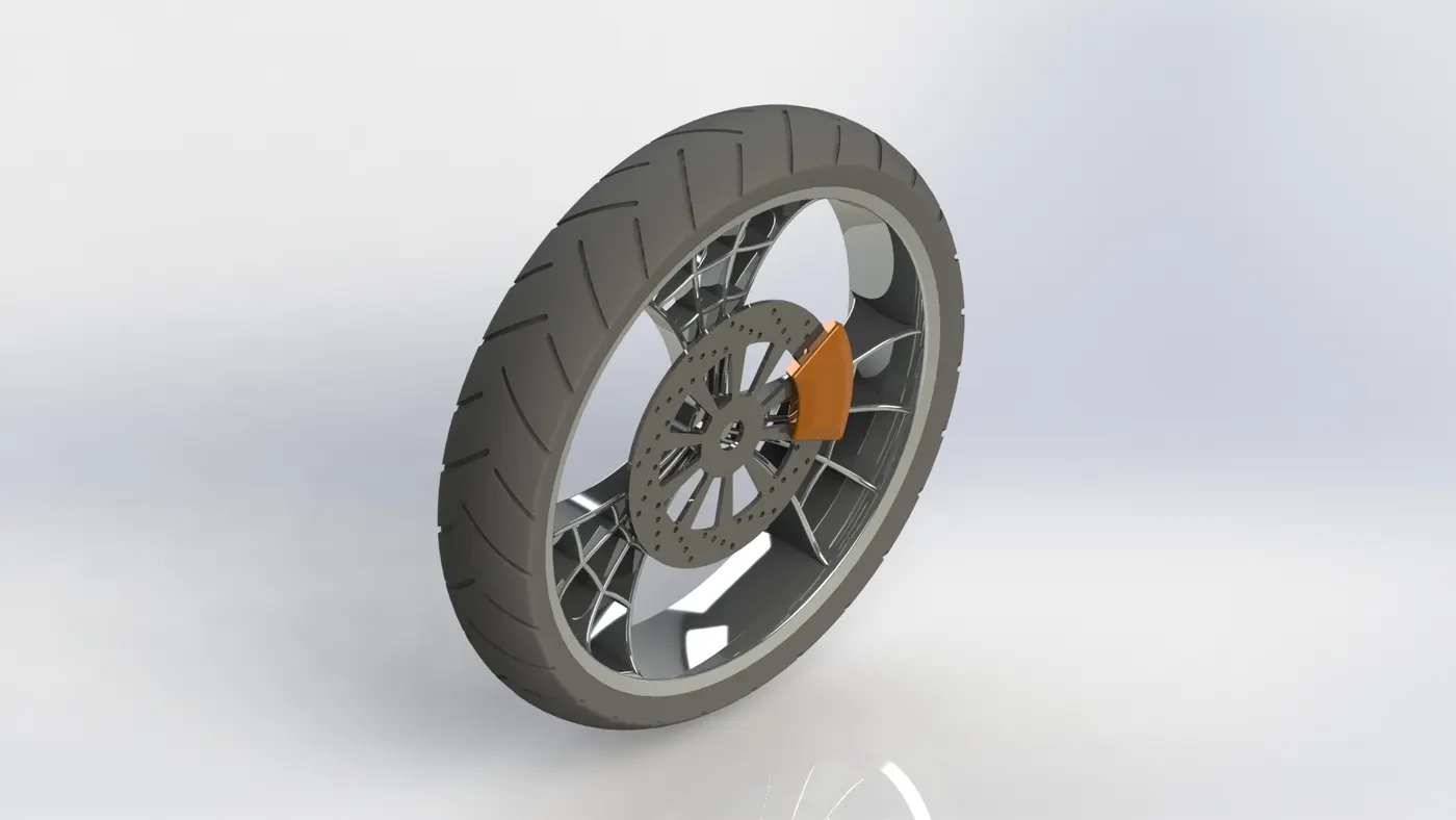
viii) Front Wheel
Front wheel contains metallic rim, spokes and rubber tyre.
Features used:
- Sketch
- Revolved Boss
- Trim Entities
- Fillet
- Extruded Boss
- Revolved Cut
- Circular Pattern
- Chamfer
- Appearance
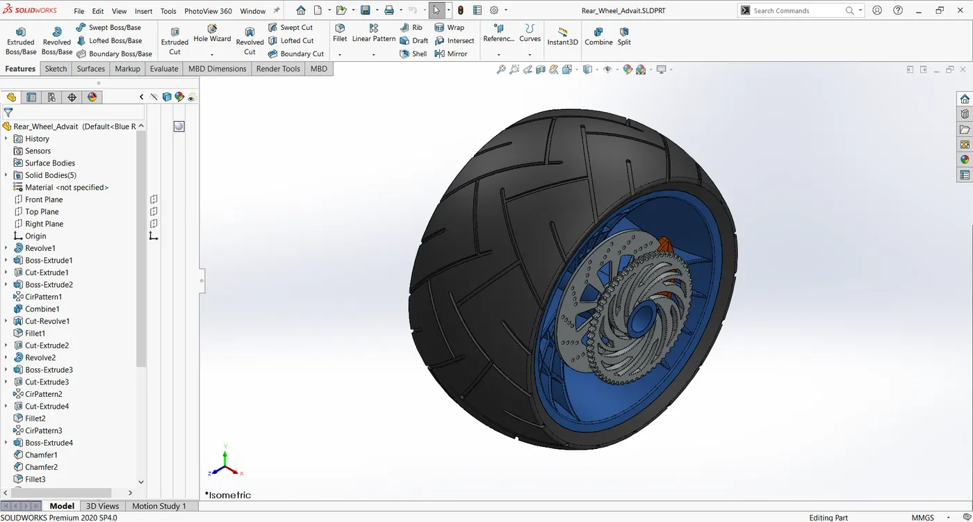
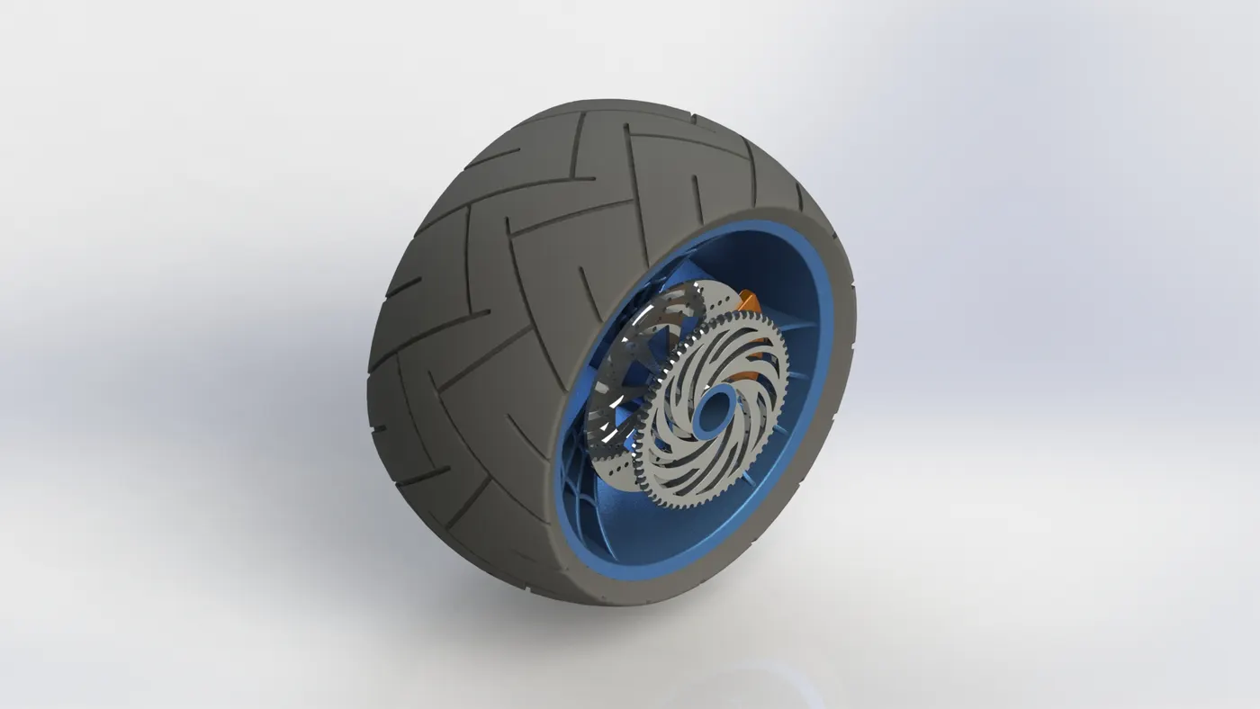
ix) Rear Wheel
Rear wheel contains metallic rim, spokes, rubber tyre and a sprocket to connect the chain from engine. The rear wheel is connected to the power train and propel the chopper relative to the ground.
Features used:
- Sketch
- Revolved Boss
- Trim Entities
- Fillet
- Extruded Boss
- Revolved Cut
- Circular Pattern
- Chamfer
- Appearance
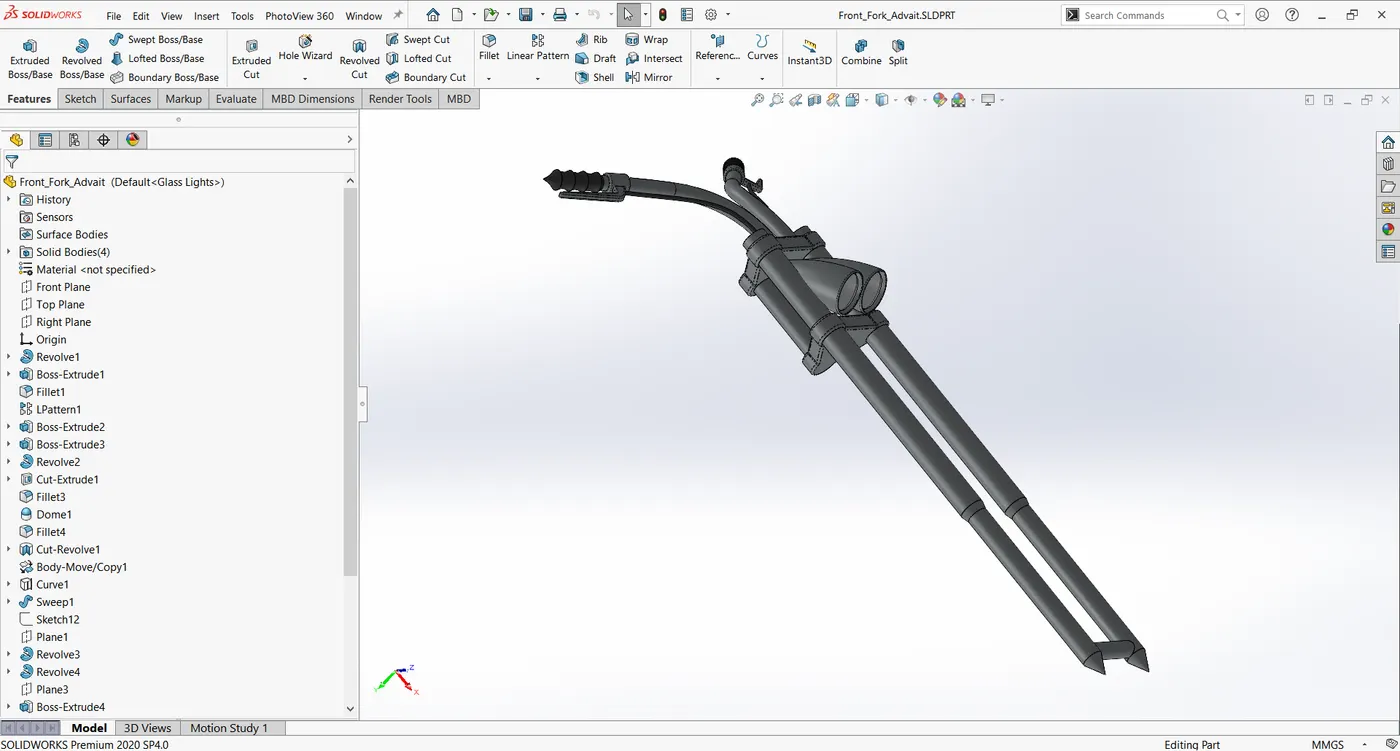
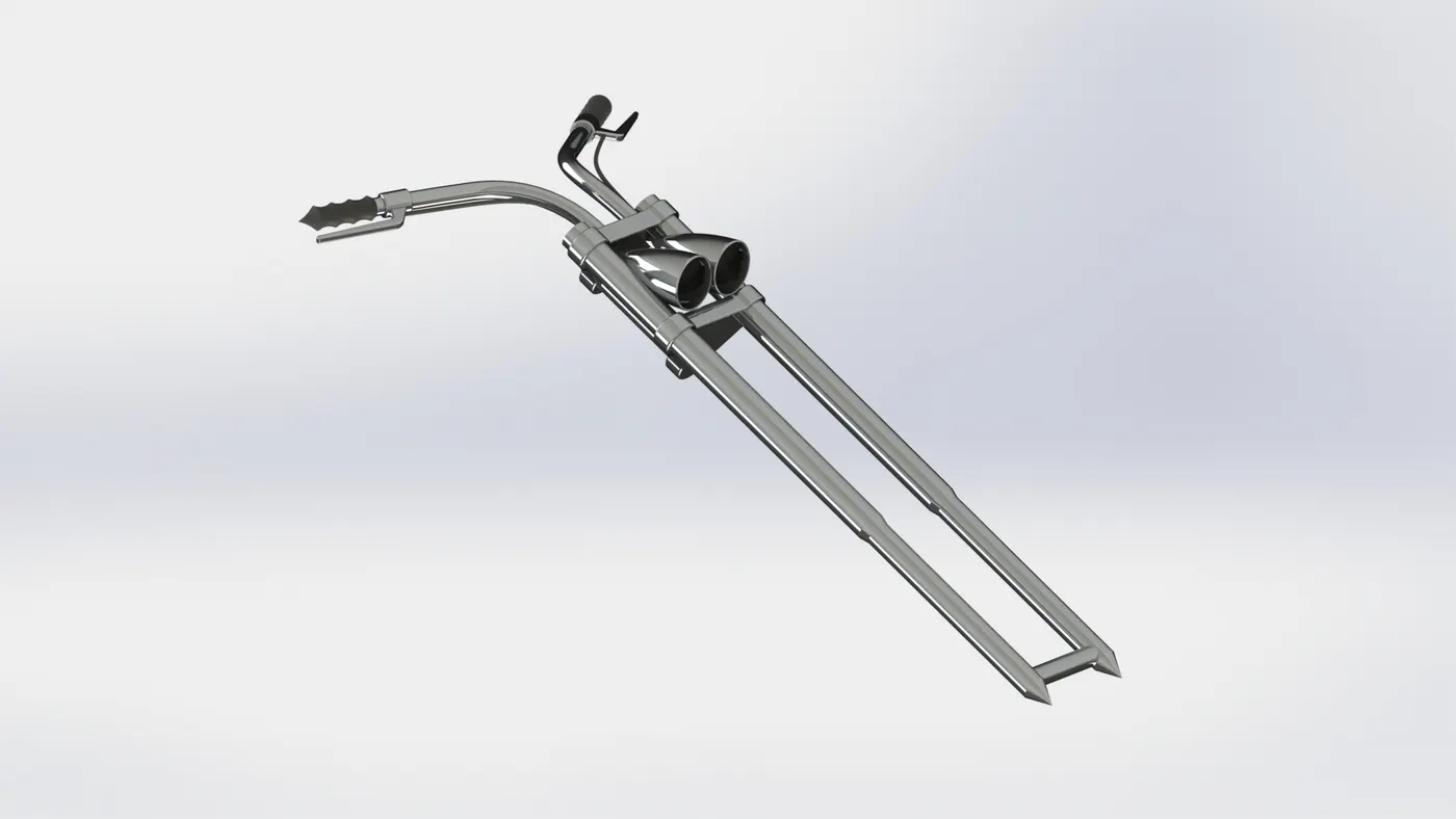
x) Front Fork
The chopper has a telescopic fork which contains the suspension system. It connects the chassis of the chopper to the front wheel. It also contains the handle bar and headlamps.
Features used:
- Sketch
- Extruded Boss
- Trim
- Revolved Boss
- Split
- Plane
- Convert Entities: Converts projection of edges and points on to a sketch.
- Dome
- Mirror: Mirrors the selected parts across a specified plane.
- Combine
- Project Curve: Creates a 3D curve which is projected on the basis of two 2D curves.
- Sweep: Creates a 3D shape by moving a 2D shape along a sketch path.
- Appearance
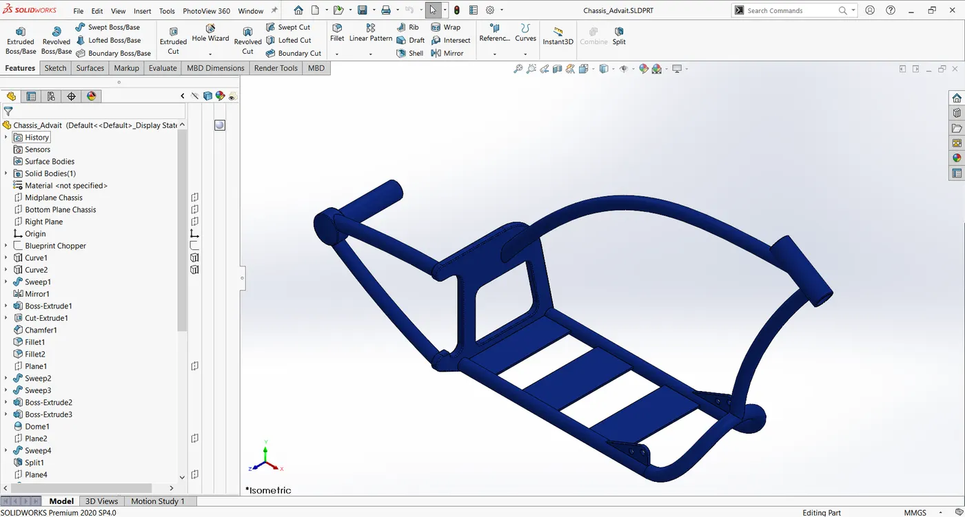
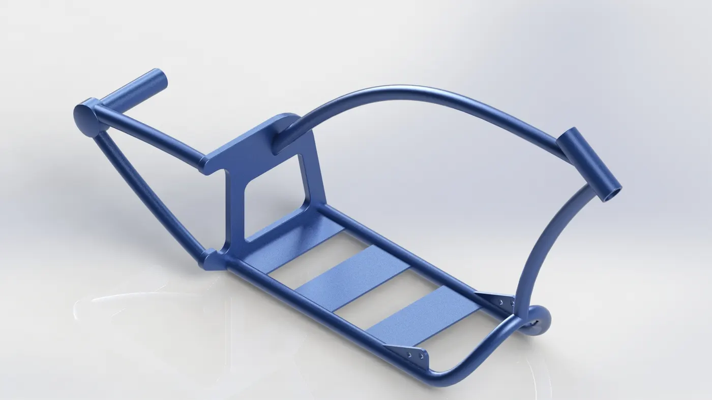
xi) Chassis
The chassis is the skeleton of the chopper. It is the structure on which every other component is attached to.
Features Used:
- Sketch
- Offset Entities
- Convert Entities
- Project Curve
- Trim Entities
- Plane
- Sweep
- Split
- Revolved Boss
- Cut Extrude
- Fillet
- Combine
- Appearance
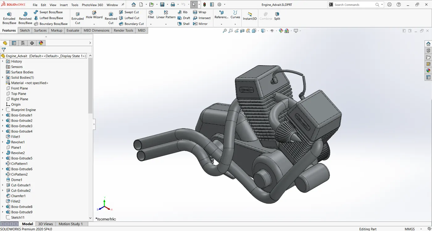
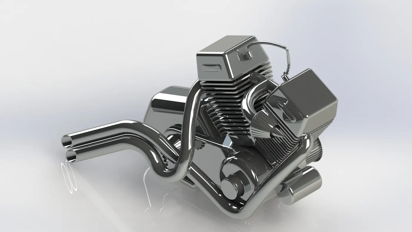
xii) Engine
The engine provides the power for the chopper. It converts chemical energy from the fuel into mechanical work. The engine rotates the wheels by the chain.
Features Used
- Sketch
- Trim
- Revolved Boss
- Convert Entities
- Extruded Boss
- Extruded Cut
- Offset Entities
- Dome
- Fillet
- Mirror
- Circular Pattern
- Project Curve
- Composite Curve: Combines two curves to create one longer curve.
- Sweep
- Appearance
xiii) Gas Tank
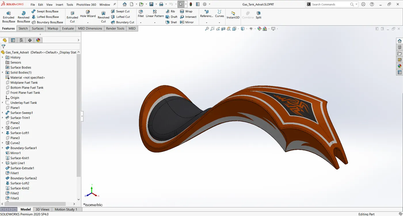
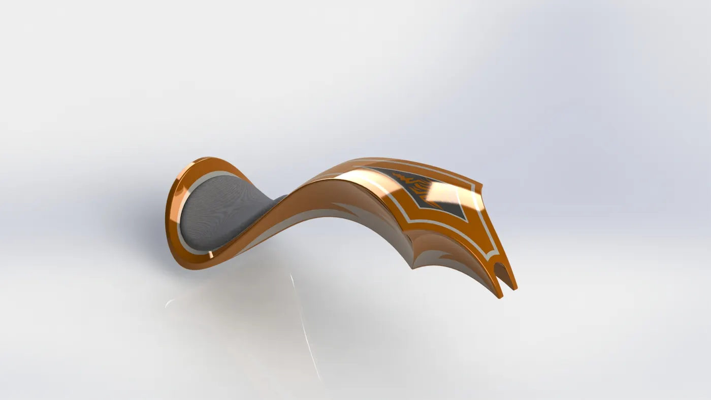
Gas tank stores the fuel needed to run the chopper. It supplies the fuel to the engines.
Features Used:
- Sketch
- Trim Entities
- Project Curve
- Convert Entities
- Surface Sweep: Creates surface by moving a curve along a path.
- Loft Surface: Creates a surface between multiple curves with least distortion.
- Surface Trim: Trims a surface wherever required.
- Surface Knit: Knits together multiple surfaces to form a single surface.
- Swept Cut: Removes material along a curve in a specified 2D shape.
- Fillet
- Appearance
- Decals
ASSEMBLY
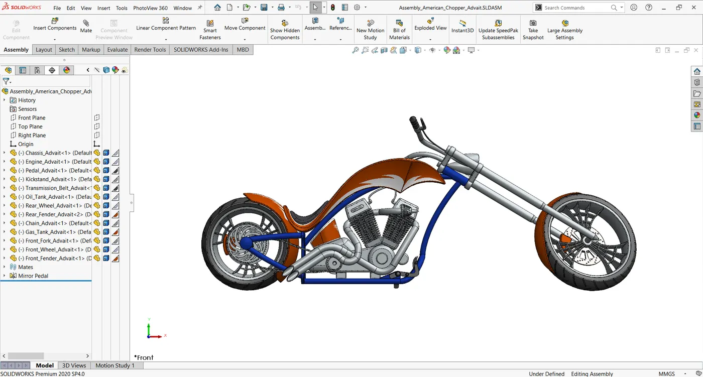
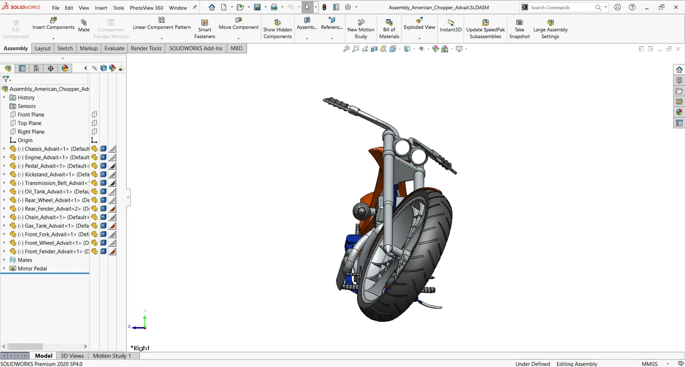
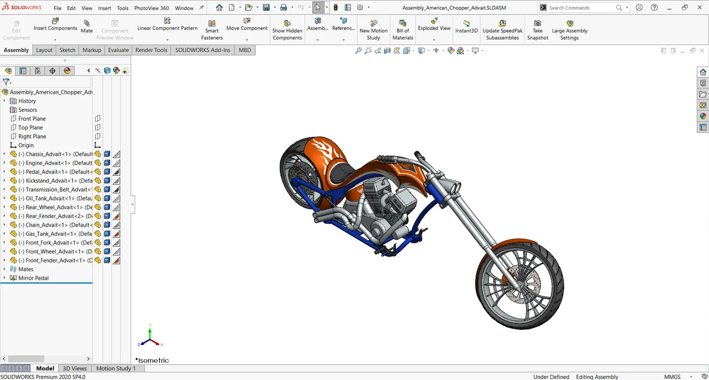
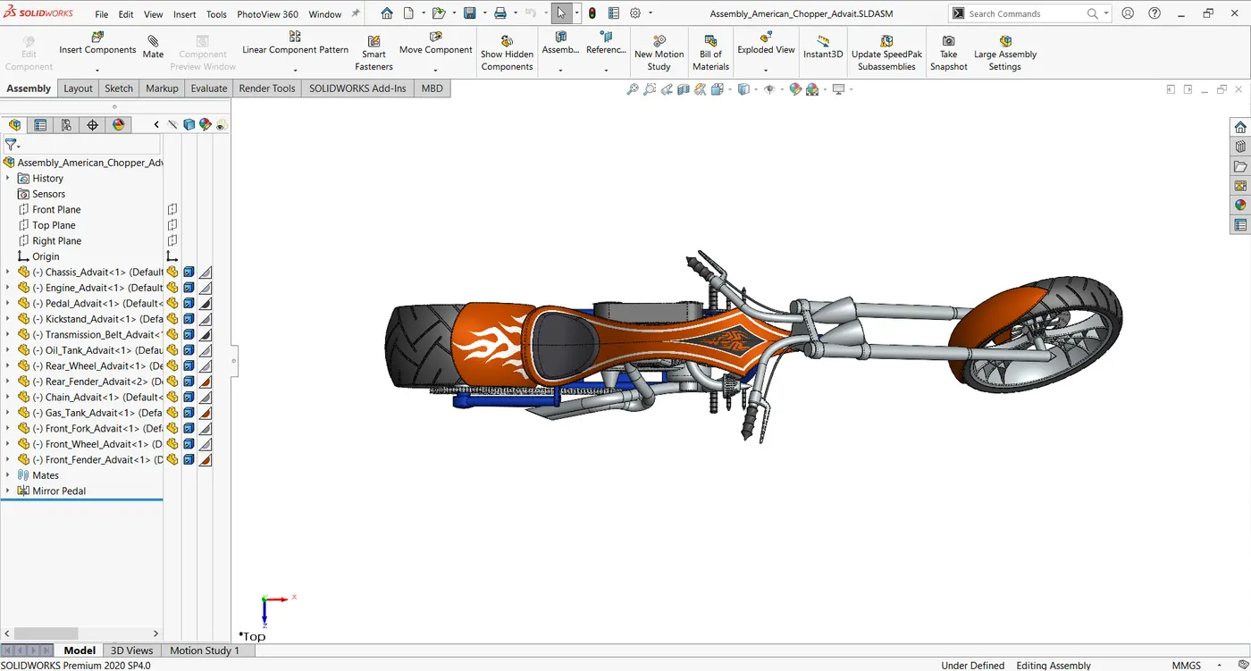
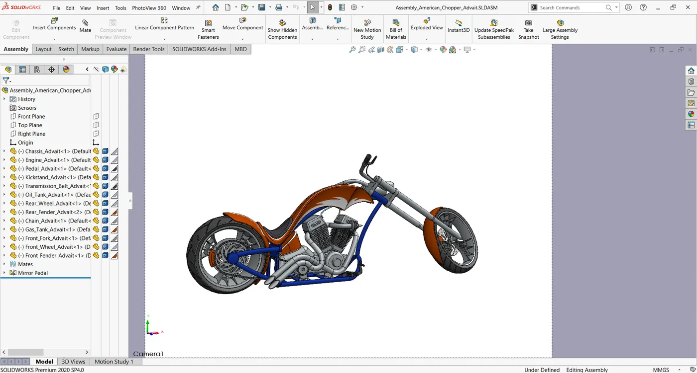
Parts modeled are assembled with respect to each other and fixed. Chassis is the first part to be added. Every other part is fixed with respect to chassis.
Mates: Mates feature is used to create geometric relationship between parts to fix their position and motion with respect to each other.
RENDERING
Rendering is the process in which photo-realistic images are created for the model designed. The environment can be set up according to the needs. Background images, camera directions, environment settings, lighting and shadows etc can be tweaked to create the best images possible.
In Solidworks, rendering can be done using Photoview 360 and Solidworks Visualize.
CONCLUSION
- Parts of an American Chopper are designed and modeled using
- Assembled the parts modeled using
- Photo-realistic rendering created using Solidworks Photoview 360 and Solidworks Visualize.