Advanced Sheet Metal Design Using NX Cad Challenge_6_Bracket
DESIGN OF A BRACKET USING SIEMENS NX CAD
OBJECTIVES
To design a bracket from a 2D sketch in Siemens NX CAD 12.
DESIGN METHODOLOGY
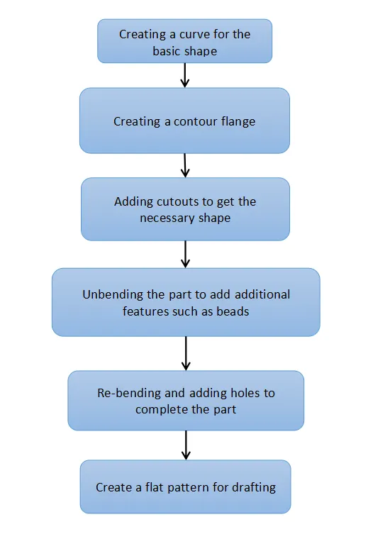
Features Used
- Sketch: Two dimensional drawings to be created with respect to a plane of view.
- Contour Flange: Creates a solid body from a sketch curve with a specified length and thickness
- Normal Cutout: Creates a cut out normal to the surface. The shape of the cutout can be given with a 2D sketch.
- Break Corner: Creates curves at sharp corners to make a smooth transition.
- Unbend: Unbends a formerly created bend or flange.
- Bead: Creates a drawn out shape along a length on a flat feature.
- Re-bend: Re-bends a former unbent operation.
- Hole: Creates a normal hole on a flat surface.
- Local Radius Analysis: Calculates the local radius at any part of the feature.
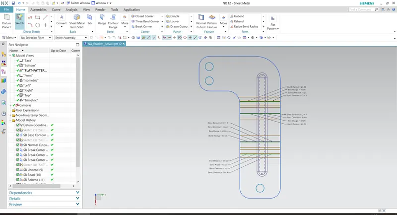
- Flat Pattern: Creates a flattened pattern of the sheet metal part for drafting purposes.
- Measure Distance: Measures the distance between any two parts for analysis.
PART VIEWS
- Front View
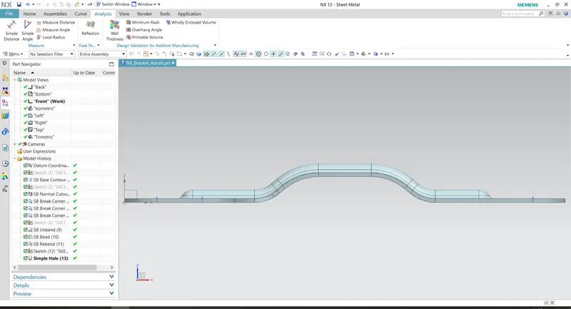
- Side View
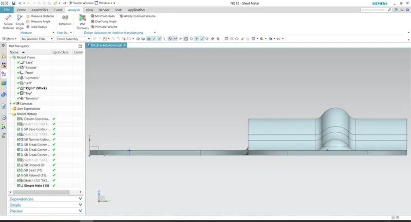
- Top View
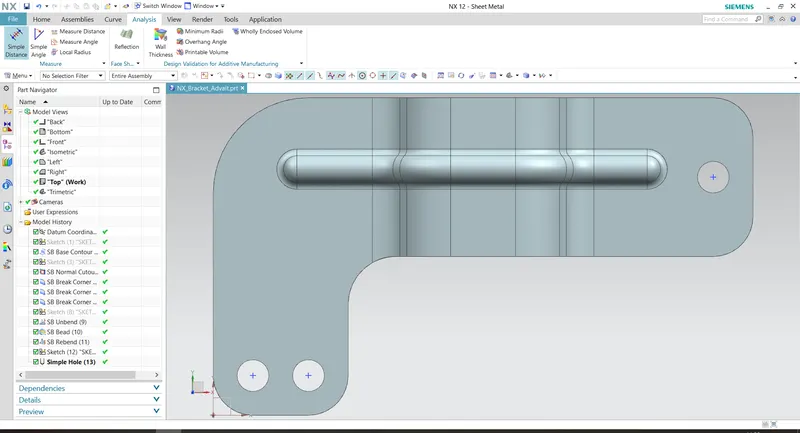
- Isometric View
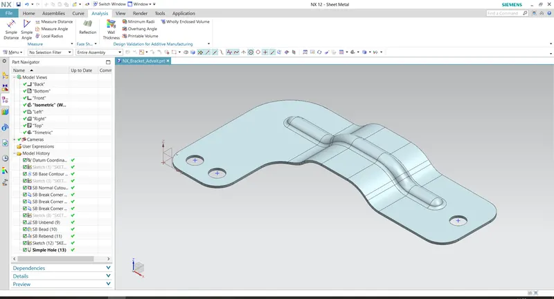
- Flat Pattern View
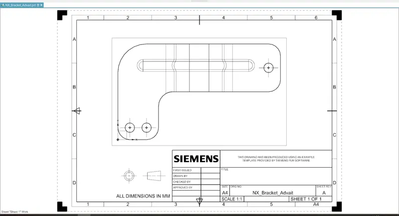
- Drafting View
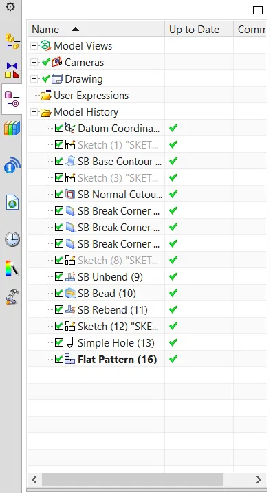
- Feature Tree
CONCLUSION
The bracket is successfully designed and drafted using NX CAD 12.