Week 8 - Challenge 5 - Core & Cavity Design
AIM
- To create a core and cavity parts for a switch bezel component.
THEORY
With plastic injection moulding, it is important to design for manufacturability. To do this, every step of the process must be taken into consideration. A draft angle will help avoid most of these issues.
A draft angle is a slant that is applied to each side of most features of an injection moulded part. The angle, which is positioned to run toward the direction of a mould’s pull and parting line, helps with releasing the part from the mould.
When developing parts for plastic injection moulding, applying draft (or a taper) to the faces of the part is critical to improving the mouldability of the part. Without it, parts run the risk of poor cosmetic finishes, and may bend, break, or warp due to moulding stresses caused by the plastic cooling. Equally important, an absence of draft may prevent parts from ejecting from the mould, damaging not only the parts, but possibly the mould itself.
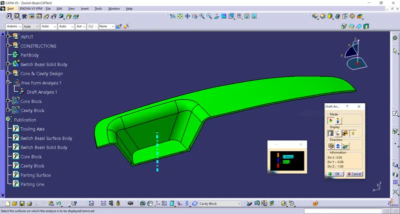
Draft analysis is a method of checking the draft angle on various faces of a part with a particular direction. Designers of plastic parts and mould tooling manufacturers can use the Draft Analysis tool to check the correct application of draft to the faces of their part. With draft analysis, they can verify draft angles, examine angle changes within a face, as well as locate parting lines, injection, and ejection surfaces in parts.
Core and Cavity: The Mould Core and Cavity are the shaped sections in either half of the mould tool which give the plastic product its final shape. The hot molten material is injected into the core & cavity and then sets hard into shape. The design of the core & cavity is essential in the correct formation of the product. Cavity is the hollow half of the mould while core is the half of the mould that fills the cavity side.
Parting Surface : Generally, an injection mould has two major components- the movable half and the fixed half. During the injection moulding process, these two halves are tightly pressed and form a sealed hollow to avoid the melt flow leakage and maintain a certain holding pressure. This pressed surface is called parting surface, and it is the biggest projection outline of the part. A parting line is the dividing line between the halves of the mould.
TOOLS USED
- Sketch
- Boundary
- Extrapolate
- Trim
- Extrude
- Fill
- Join
- Close Surface
- Publication
PART IMAGES
- Draft Analysis of the Switch Bezel :
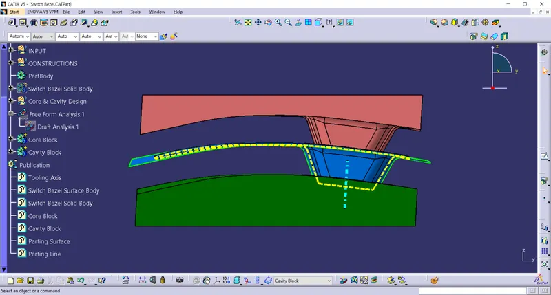
- Front View of Core and Cavity :
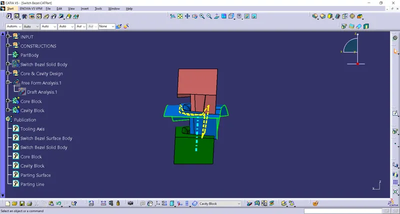
- Side View of Core and Cavity :
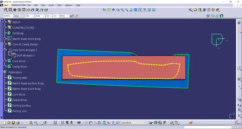
- Top View of Core and Cavity :
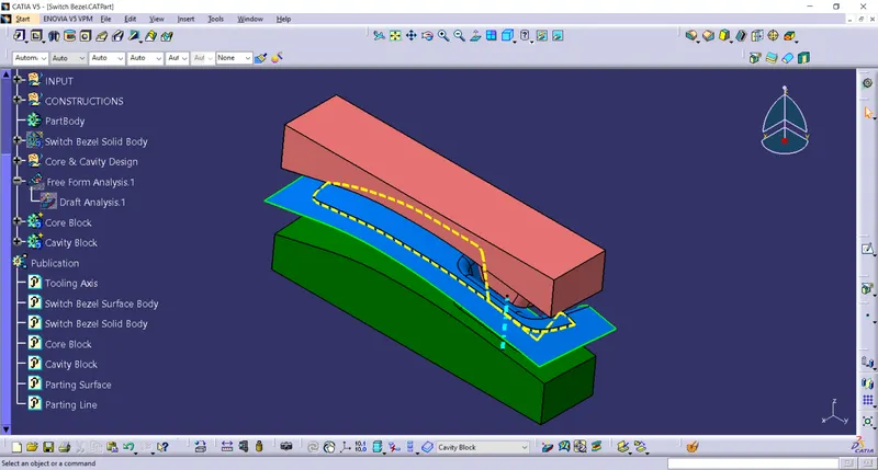
- Isometric View of Core and Cavity :
CONCLUSION
- Core and Cavity designed for the previously designed Switch Bezel component.