Week 8 - Challenge 1 - Base Bracket Design
Base Bracket Design
Introduction:
To create a Base Bracket Plastic part through a given category. A Surface and perform a Draft Analysis on the ultimate plastic part. In this project, we tend to square measure planning a base bracket victimization given category A surface. The approach includes the creation of a sophisticated B surface keeping a 2.5 mm thickness in mind for the entire part. The design conjointly enclosed category C creation from the given parent surface.
Tooling Axis:
Material Chooses:
- Polyethylene terephthalate (PETE), is the chemical name for polyester.
- PETE is a clear, strong, and lightweight plastic Material.
Class A:
- Class A surface it will already design by an automotive designer.
- It describes the final product surface for the aesthetic parts of the car.
- The portion with which other materials first interact.
Class B:
- Class B surfaces are the secondary surfaces.
- The surface is designed by a plastic designer.
- The Class B surface is not visible outside.
- Most of the ejection of plastic part marks are not visible on the class A surface.
Class C:
- The Class C finishing of more imperfections than Class A or B.
- Closing the Class A and Class B surface components.
Draft Analysis:
- It is used to analyze whether our part model created in CAD is manufacturable based on the draft condition applied.
- It will help you gather the draft angle on multiple surfaces without the need for manual measurements.
- Draft Analysis is applicable for 3D part models.
Objectives:
- Creation of Class A Surface.
- Creating of Tooling Axis.
- Design of B surface and design of C surfaces.
- Joining both the A, B, and C Class Surfaces.
- Draft Analysis of A character and final plastic element.
Tool Used:
- CATIA V5
- In this project, we tend to square measure planning a base bracket victimization given category A surface.
- The approach includes the creation of a sophisticated B surface keeping a 2.5 mm thickness in mind for the entire part.
- The design conjointly enclosed category C creation from the given parent surface.
Constraints:
- No changes in Class A area units are Allowed.
- Part thickness can't deviate by an additional than ±30%
- All styling rules ought to be strictly followed.
- All Surfaces ought to be closed before changing to solid parts.
- All faces ought to meet the allowed draft necessities.
Class.A_Surface:
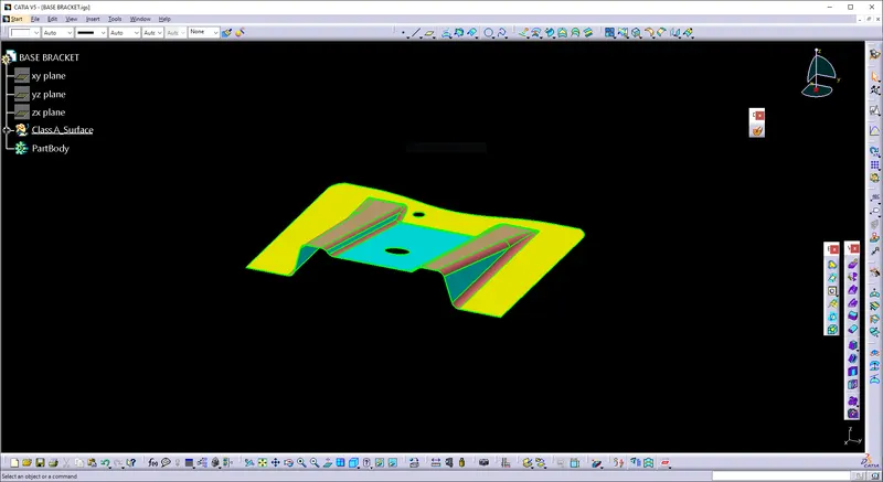
- To continue with the look method initially we want to seek out the tooling axis for the surface and check for all the drafts victimization the Draft Analysis tool of CATIA.
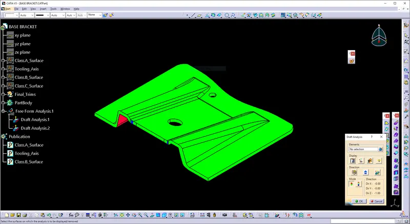
Draft Analysis for Surface A:
- The analysis is done for the 0.001-degree draft. So as can be seen all the surfaces are more than 0.003-degree.
Creating of Tooling Axis:
- Create an intersection of CLASS A surface with the Z-axis plane and from the intersection create the tooling axis as shown below.
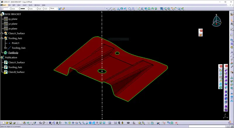
- Line shown in dotted White is our tooling axis.
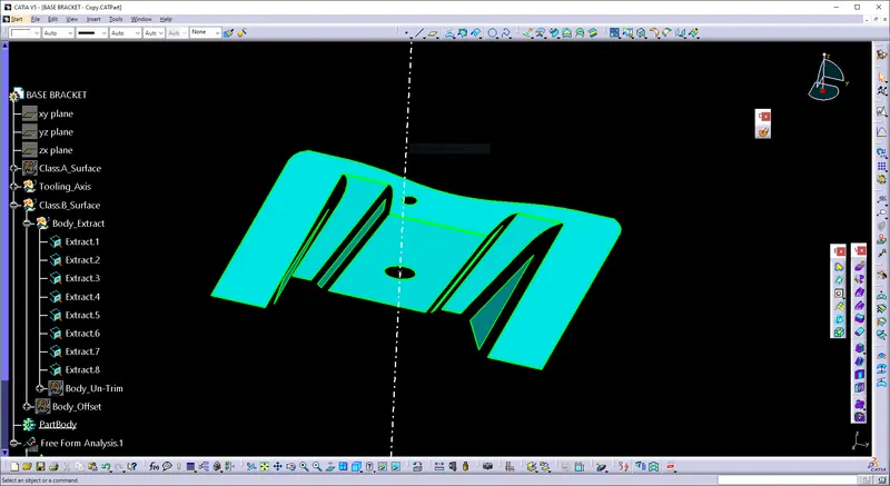
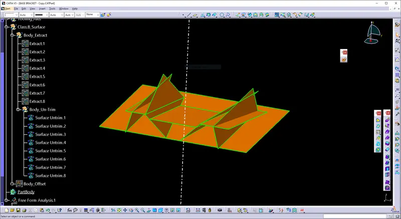
Extract the Class A body and joins with Un-Trims:
Creation of Class B Surface :
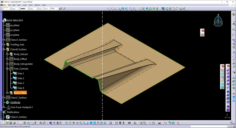
- Now for Class B creation, we've got extracted surfaces from category A and unclipped them to get the first parent surface.
- These surfaces square measure and then offset to the specified thickness.
- After antagonistic, all the surfaces square measure cut into the specified form.
- Required fillets square measure given to the surfaces.
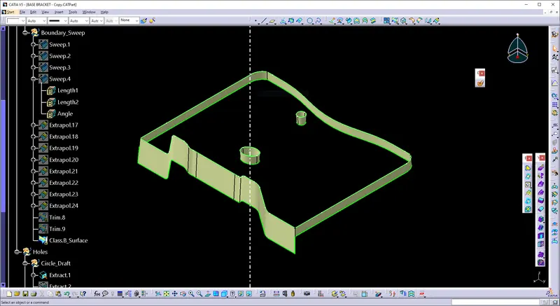
Creation of Class C Surface :
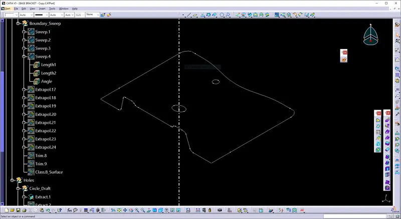
- For making this surface we've got extracted the boundary of sophistication.
- A victimization multi-extract so we reborn it to a swish curve.
- Now, this swish curve is swept in the draft direction with a three deg draft.
Draft using at all corners:
Final Trims:
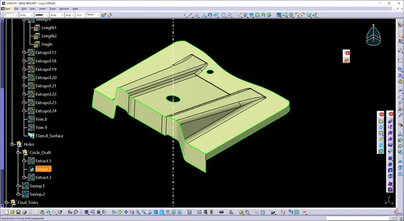
Class A Surface & Class C Surface Join :
- To make certain that there's not any open boundary between class A and Class C, we've used the be part of the choice to produce the only body.
- This can be done to create certain that the parting line does not lie between these 2 surfaces.
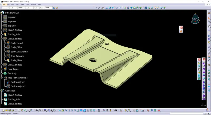
Both Class A & B Surface & Class C Surface Join :
- For this Part, we've got cut the above-shown surface with the category B surface exploitation of the trim feature.
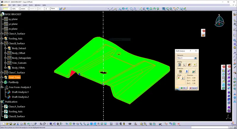
Draft Analysis on the Final Component of Class A, B, & C :
- In this analysis, the main tooling axis is taken draft reference.
Result: