Week 8 - Challenge 1 - Base Bracket Design
AIM: Create the Base Bracket Plastic component through the given Class-A surface
Objectives:
Create Tooling Axis.
Create Class B and Class C surface.
Create a solid part out of surface modelling.
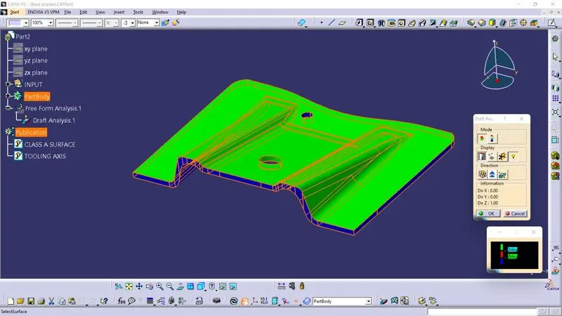
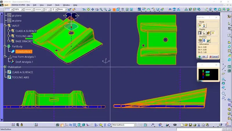
Draft Analysis of Class A surface and final plastic component.
METHODOLOGY :
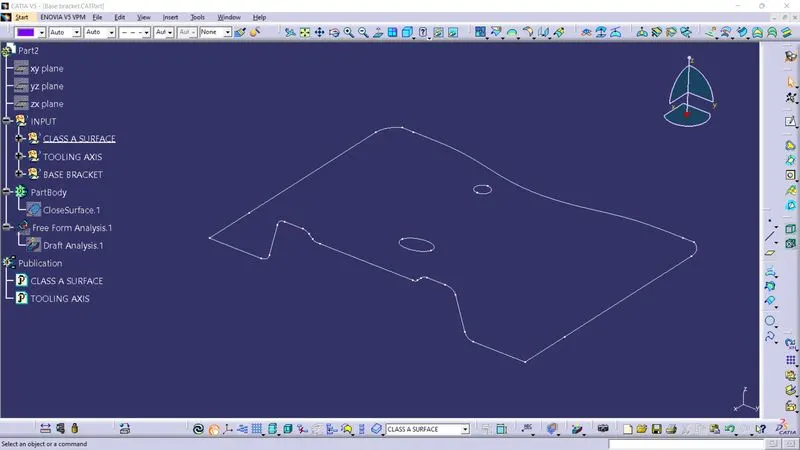
Check Class A surface for gaps using BOUNDRY command. 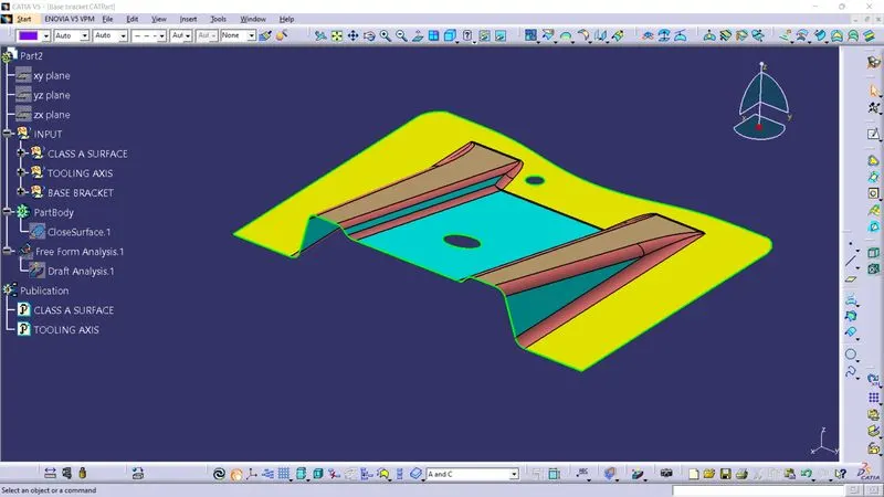
CREATING TOOLING AXIS :
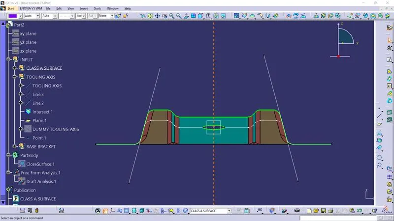
For creating a tooling axis first we need to create a dummy tooling axis. For that we need to create a point at CG once we create a point. We need to create a line which is going to be a dummy tooling axis for now, The reason behind making dummy tooling axis is we don’t know exactly which is y and z axis. After that we create plane. After the we take a intersection with that component and plane.
After that we figure out the surface which is going to create a problem and take that into consideration and extend the lines of that angle surface and bisect it. After bisecting we get the tooling axis.
CLASS B :
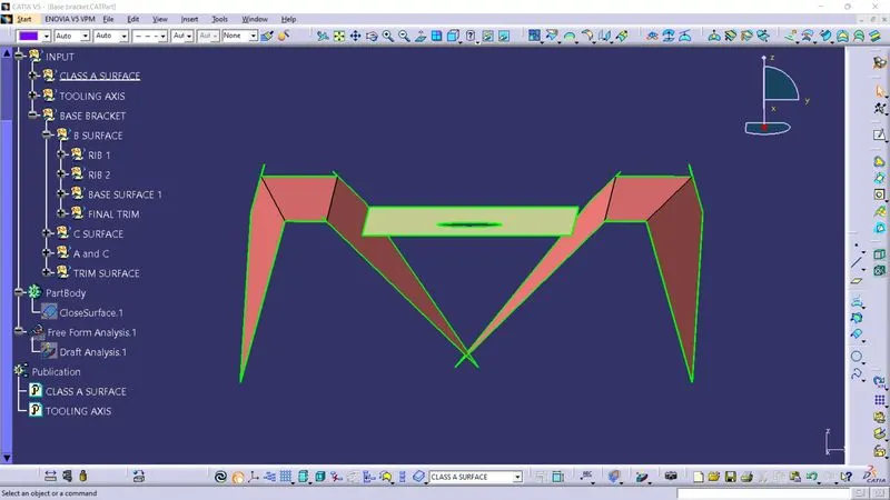
For making B surface we have to extract Class A surface seperately and then offset it with 2.5mm. And JOIN the surfaces by trimming.
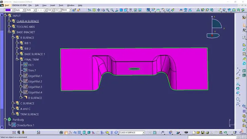
CLASS C :
Class A-Surface and Class B-Surface are connected by C-Surface. The command Sweep is used to construct it. The class A surface's boundary is swept at a 90 degree angle.
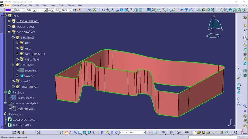
JOINING A AND C :
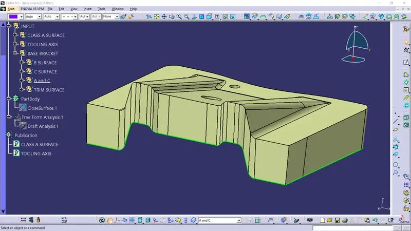
FINAL JOIN :
Joining all the surface Class A, B and C.
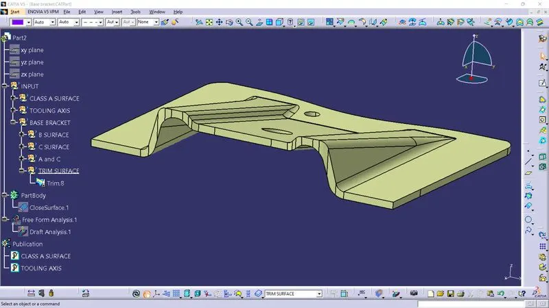
CLOSE SURFACE :
Define the part body by using the Closed Surface command in Part Design, the component's solid body is created.
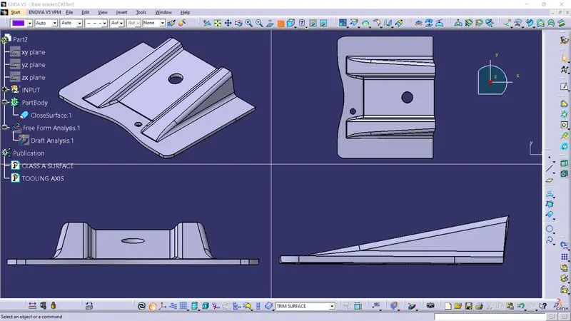
DRAFT ANALYSIS :
Report
1
Parts which have 90 degree profile are difficult to eject from the tool. For that minimum draft angle is provided to every part in order to remove the component easily From the tool. We provide direction in which the component is removed easily from the tool.
Draft analysis is perform on the component where the ejection of the materials happens after the material is made inside the tool. In automotive Industry parts like hood, fender, roof, side doors, back doors etc are made by injection moulding process. So this parts are removed from panel dies. If the considerable amount of draft angle is not provided the removal of the component from tool will be difficult and it will destroy the component while removal through friction.
2
For creating a tooling axis first we need to create a dummy tooling axis. For that we need to create a point at CG once we create a point. We need to create a line which is going to be a dummy tooling axis for now, The reason behind making dummy tooling axis is we don’t know exactly which is y and z axis. After that we create plane. After the we take a intersection with that component and plane.
After that we figure out the surface which is going to create a problem and take that into consideration and extend the lines of that angle surface and bisect it. After bisecting we get the tooling axis.