Week 9 - Attachment Feature Creation (Ribs & Screw Boss) - Challenge 1
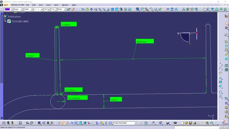
AIM : Create the rib for the Drill Handle considering the design rules and create the Screw boss for the Drill Handle and also perform draft analysis.
OBJECTIVES :
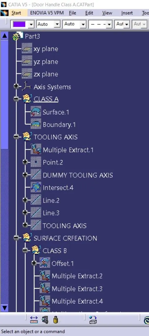
- Create the Tooling axis by using the bisecting method.
- Design the class-B and class-C surface and join them.
- Create the solid feature by surfaces we create.
- Design the required Ribs and Screw Boss and analysis them.
- Perform the Draft analysis for the final component.
METHODOLOGY :
Firstly check for the Gaps in the surface by using boundry command, if you found the gaps we have to fill it by using various command such as multi-section surface or blend. After that we can proceed further.
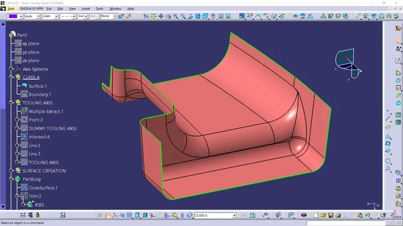
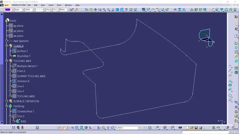
As we can see there no gaps in Class A surface so we can proceed further.
TOOLING AXIS :
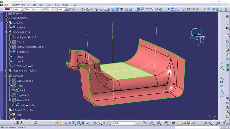
Tooling direction is the direction in which the moul pulls apart. Class A is surface is analyse to create a tooling direction. As the mold is made upm of two halves movable and fixed half. As the Core block is movable half so it is necessary to create a correct tooling direction in order sucessfully pull the component after the process without any defects after the shrinkage.
Class B surface :
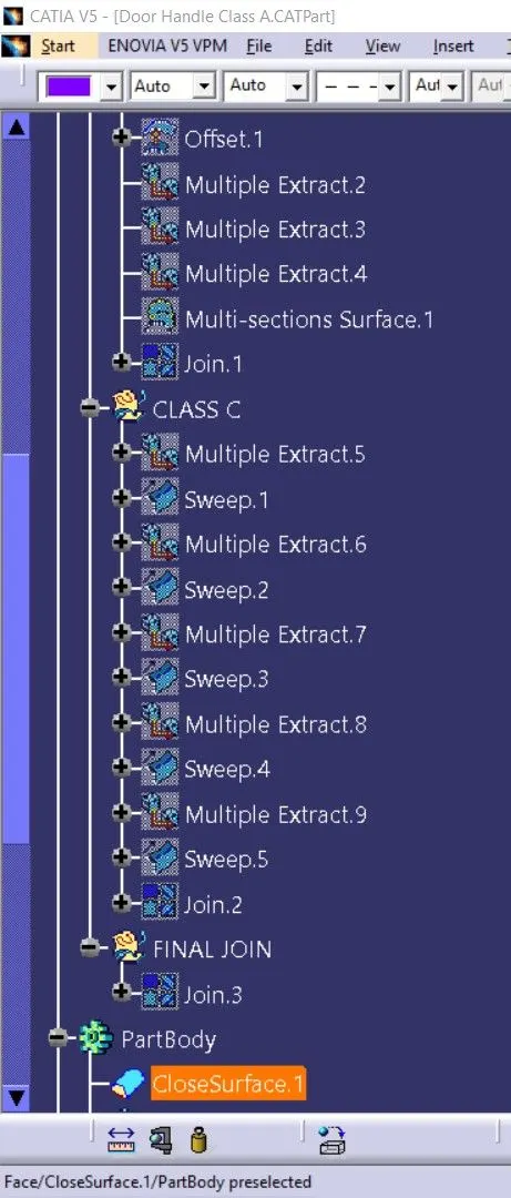
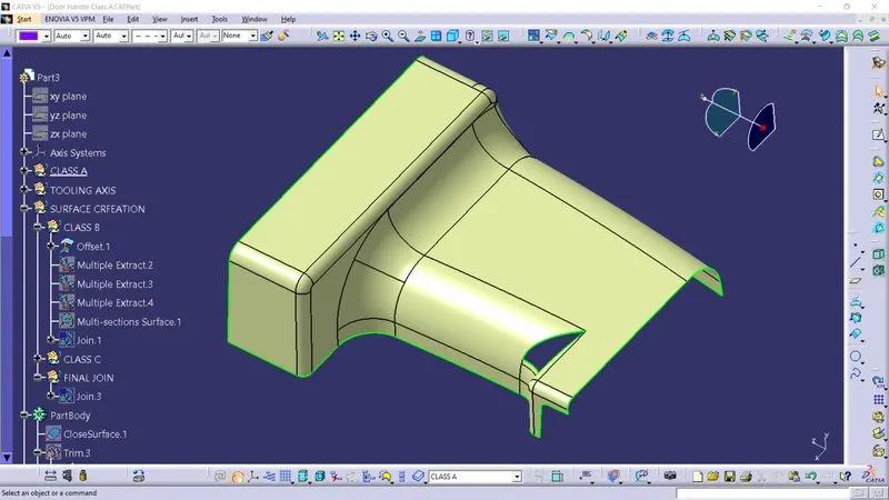
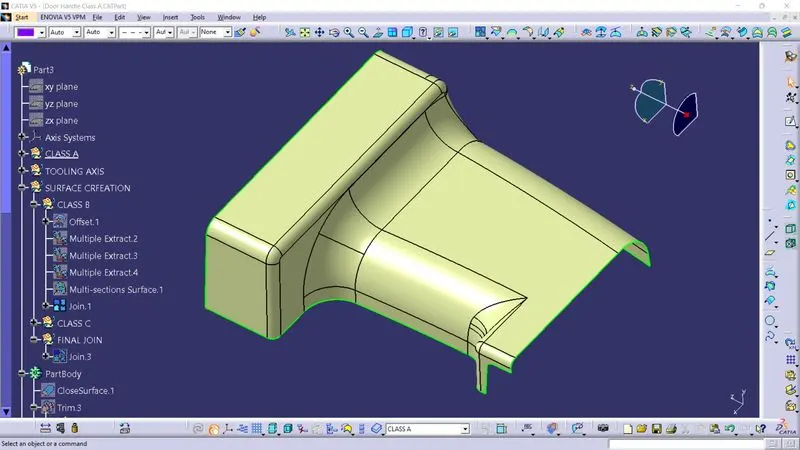
To create a Class B surface first we have to Extract and Offset Class A surface by 2.5mm. And filled the gaps using Multi- section surface and blend command.
Class C surface :
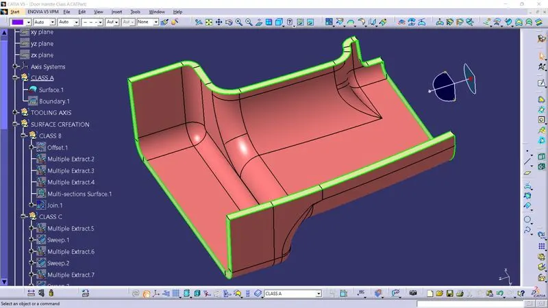
Class A and Class B surface is Joined using Class C surface.
Class C surface is created using swept surface command with respect to Class A surface.
JOINING ALL THE SURFACES :
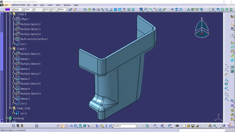
Joining Class A, Class B and Class C surfaces.
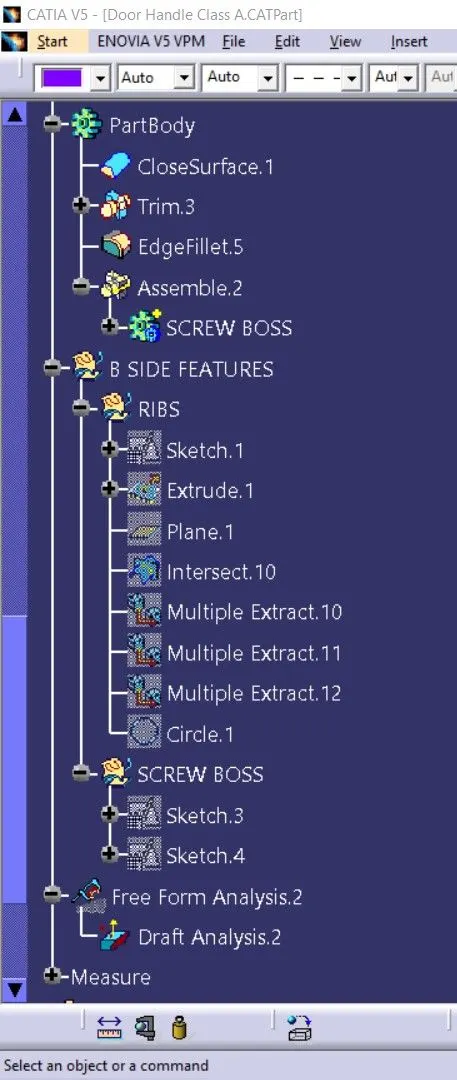
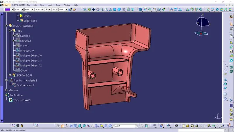
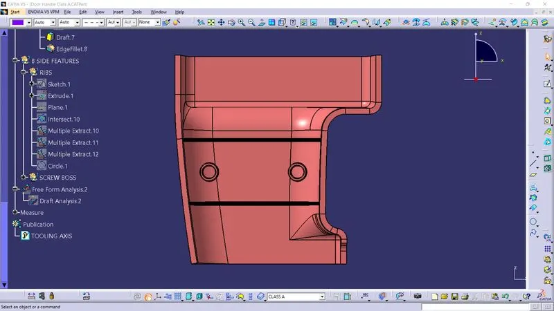
RIBS :
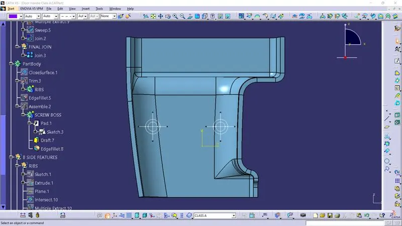
SCREW BOSS :
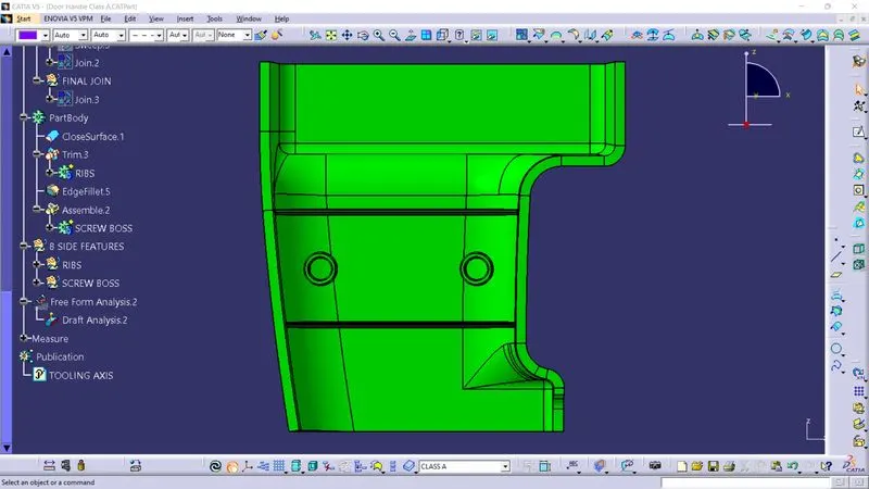
DRAFT ANALYSIS :
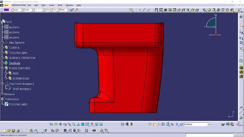
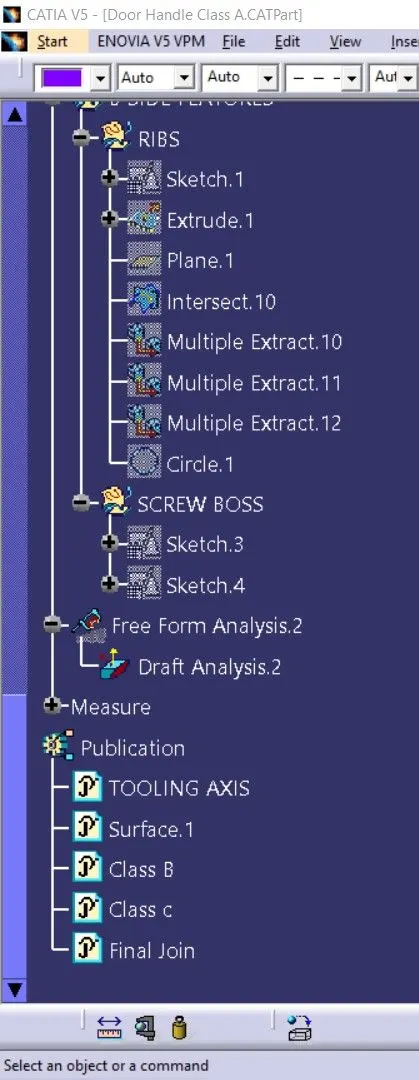
TREE STRUCTURE :