Week 8 - Challenge 2 - Switch Bezel Design
Firstly Check the continuity of surface
Checking the connectivity of the Class A Surface if there is no gap between the components using the Join command or by using the Boundary Command.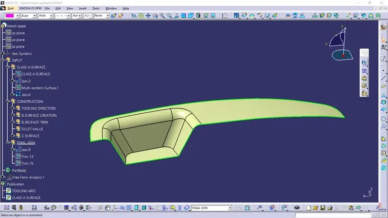
Tooling Axis
The Tooling Axis is created using Bisecting Line Method.
- Bisecting Line Method:
Base is extracted from class A surface and a point is created at the centre.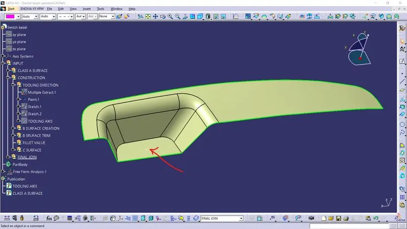
Axis system is inserted by keeping the current feature off.
Intersection is created at yz plane. And two inclined lines were created.
Then bisecting lines with the two inclined lines were drawn.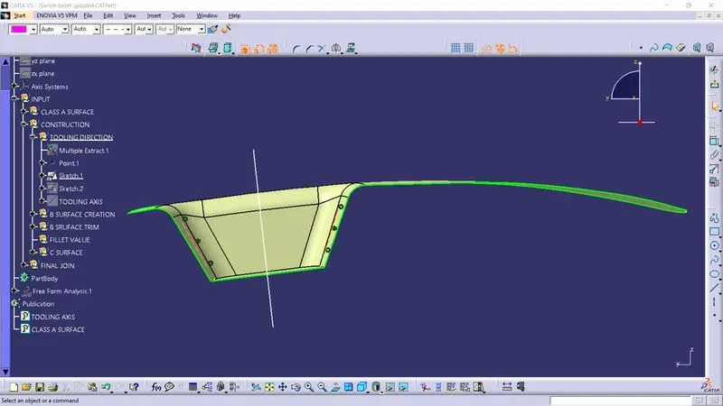
Now the same procedure is done along the xz plane but on one side we don’t have inclined lines so the centre point is used to extrude a line along the z-direction and gave a measurement of 5 degrees
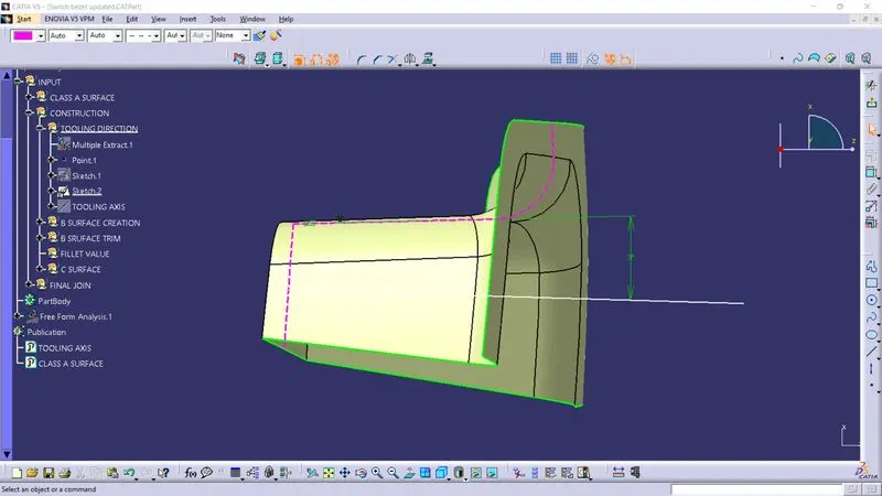
With these two lines from sketches 1 and 2, the bisecting line is created.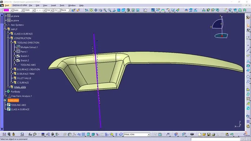
Class B Surface
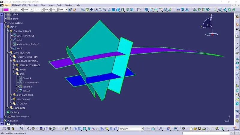
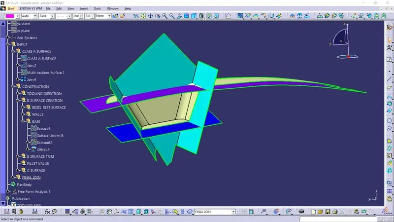
For class B surface extract every side of the class A surface one by one the offset it by 2.5 mm and untrim it then extrapolate so that they intersect each other and get and easily trimmed off.
After extrapolation use trim command to cut the portion when is not needed.
Required corners are to be trimmed (Fillet value - Thickness of the component)
Class C surface
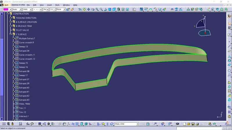
The required outer edges of the A-Surface were extracted using Multiple Extract.
Then for avoiding the patches the curve is smoothened using the Curve Smooth option.
Then by using the sweep command the surface was created.
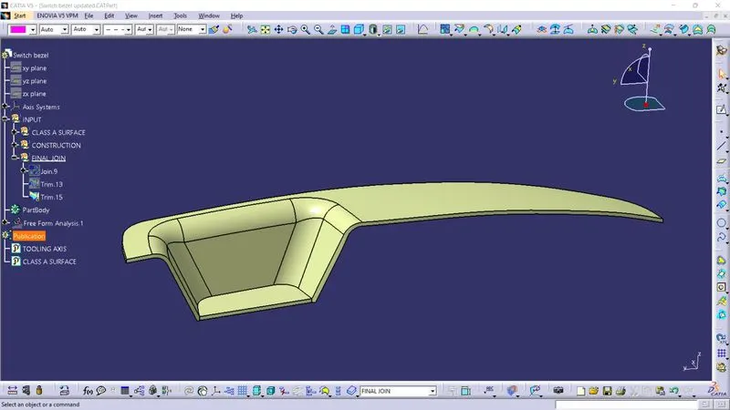
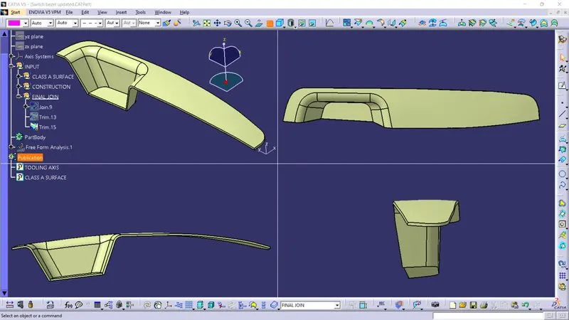
FINAL TRIM
Closed Surface
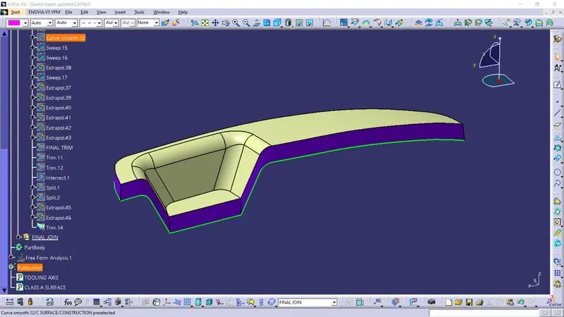
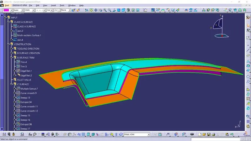
The class A and Class C surfaces are joined together by removing the gaps in-between them with the help of extrapolation with tangent continuity and Trim surface.
After that the resulted surface is trimmed with the class-B surface.
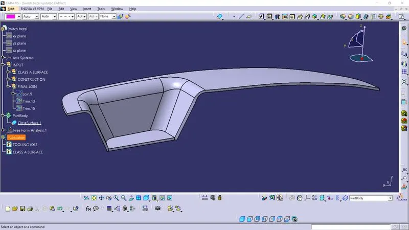
Then, by defining the part body by using the Closed Surface command in Part Design, the component's solid body is created.
DRAFT ANALYSIS
First we have to change the view mode into 'Material' then only we can run the draft analysis.
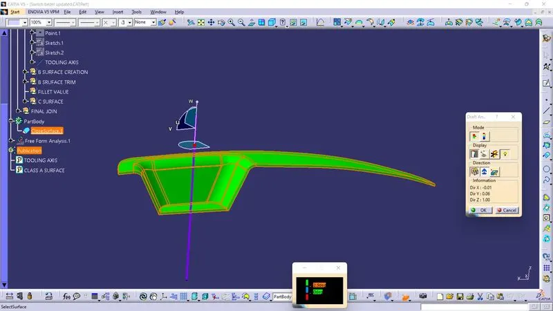
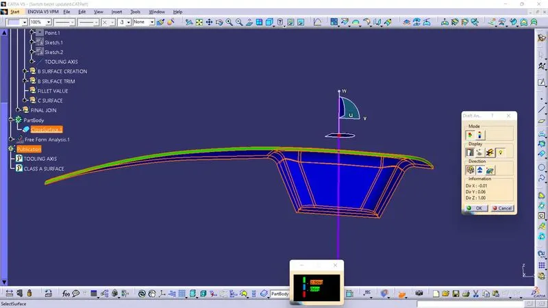
After changing the view mode, compass will get activated.Click on the compass and place it on the tooling axis in correct direction. If it is hard to place in right direct click on the Inverse draft.
Then, by selecting the quick analysis mode, the nominal value will be 3 degrees and checked for the component's draft angle.
The green colour area shows that it satisfies the 3-degree draft angle. If not satisfied then by using the Running point tool the area is measured and then altered to get a successful draft for the created tooling direction.