DC Motor Control
AIM:
- Run MATLAB demo ‘Speed control of a DC motor using BJT H-bridge’. Modify the model such that armature current doesn’t shoot up when motor changes direction from forward to reverse.
- Refer to help section of ‘The Four-Quadrant Chopper DC Drive (DC7) block’. Compare it with H-bridge model.
- Make a suitable EV model using DC7 block and make result report.
- Explain in a brief about operation of BLDC motor.
STUDY 1:
The Bipolar Junction Transistor (BJT) is a three terminal semiconductor device capable of two p-n transistor which are able to amplify or magnify a signal.The three terminal of device are collector, base, emitter.
The BJT operates as an IGBT in power switching application.When BJT is conducting it operates as at saturation region a forward voltage Vf is developed between the base and emitter.Thus the IGBT block can be use to model the BJT device.
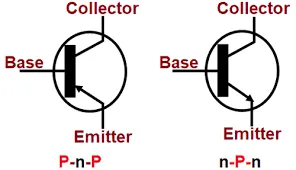
The IGBT block does not simulate the gate current controlling the BJT or IGBT.The switch is controlled by simulink signal(1/0).The DC motor with specification of 5HP 24V 1750 rpm is used in the model.It simulates a fan type of load where load torque is proportional to square of speed.The duty cycle can be varied from 0 to 100% using pulse generator block so that armature voltage can be varied from 0 to 240V.
SIMULATION MODEL:
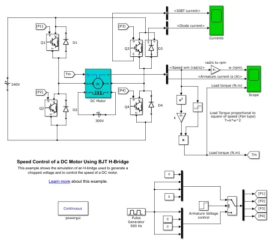
The H-bridge consists of four BJT and diode models.Two transistors are switched simulatenously i.e Q1 Q4 or Q2 Q3. When Q1 and Q4 are fired, a positive voltage is applied to the motor and diodes D2-D3 operate as free-wheeling diodes when Q1 and Q4 are switched off. When Q2 and Q3 are fired, a negative voltage is applied to the motor and diodes D1-D4 operate as free-wheeling diodes when Q2 and Q3 are switched off.
SIMULATION RESULT:
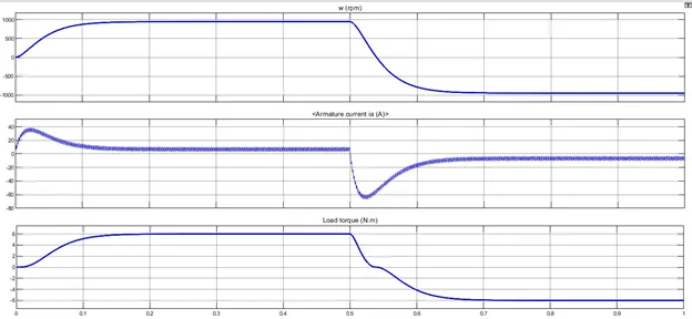
AT V=180V
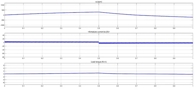
The motor starts in positive direction with duty cycle of 75% i.e Voltage of 180V.At t=0.5sec armature voltage is suddenly reversed so that the motor runs in negative direction . Initially there is spike in armature current when the motor speed increases and remains constant when the motor runs in positive direction.As the motor runs in negative direction there is sudden shoot up in armature current in negative direction.
AT V=120V
When the duty cycle changes to 50% i.e Voltage of 120V is applied to motor so that speed decreases.The armature current shoot up decreases as the motor runs in negative direction.
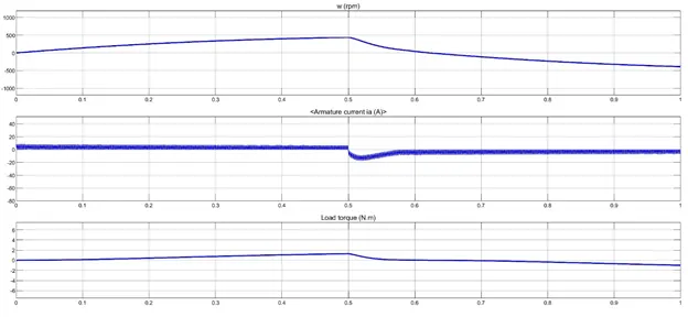
AT V = 96V
As the voltage decreases speed decreases so that armature current value decreases slightly when the motor runs in negative direction. The torque value almost come to zero.
RESULT:
As the armature current does not shoot up only when the load torque remains constant.Thus the armature current shoot up when the motor changes direction from forward to reverse direction.
STUDY 2:
The DC7 Four-Quadrant Chopper 200HP DC Drive model is shown below
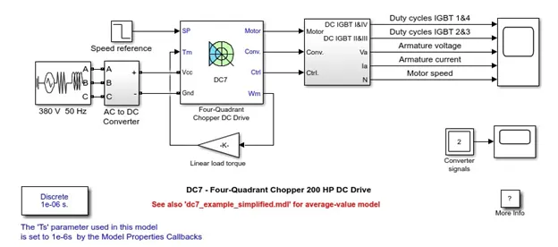
The 200 HP DC motor is separately excited with a constant 150 V DC field voltage source. The armature voltage is provided by an IGBT converter controlled by two PI regulators. The converter is fed by a 515 V DC bus obtained by rectification of a 380 V AC 50 Hz voltage source. In order to limit the DC bus voltage during dynamic braking mode, a braking chopper has been added between the diode rectifier and the DC7 block.
The first regulator is a speed regulator, followed by a current regulator. The speed regulator outputs the armature current reference (in p.u.) used by the current controller in order to obtain the electromagnetic torque needed to reach the desired speed. The speed reference change rate follows acceleration and deceleration ramps in order to avoid sudden reference changes that could cause armature over-current and destabilize the system. The current regulator controls the armature current by computing the appropriate duty ratios of the 5 kHz pulses of the four IGBT devices (Pulse Width Modulation). For proper system behaviour, the instantaneous pulse values of IGBT devices 1 and 4 are opposite to those of IGBT devices 2 and 3. This generates the average armature voltage needed to obtain the desired armature current. In order to limit the amplitude of the current oscillations, a smoothing inductance is placed in series with the armature circuit.
SIMULATION RESULTS:

COMPARISON
|
FOUR QUADRANT CHOPPER |
H-BRIDGE CIRCUIT |
|
The AC supply of 380V 50Hz is used to power the drive |
The DC supply of 240V is used to supply to the circuit. |
|
It operates in four quadrants i.e forward motoring,forward braking,reverse motoring and reverse braking. |
It operates only in two quadrants i.e forward motoring and reverse motoring. |
|
Type-E Chopper circuit is used. |
BJT H-Bridge circuit is used. |
|
Smoothing inductance is added to reduce armature current ripples |
No smoothing inductance is added to reduce armature current ripples. |
|
Speed control and regeneration is possible. |
Speed control and regeneration is not possible. |
|
Reference speed is needed. |
No reference speed is needed. |
|
It can be used for EV applications. |
It cannot be used for EV application as it operates only in forward and reverse motoring. |
RESULT:
Thus the comparison of Four quadrant chopper with H-Bridge circuit in DC motor is shown.
STUDY 3:
In this model we need to change the AC supply and Converter into DC source ,speed reference into own drive cycle and linear load torque into vehicle dynamics.
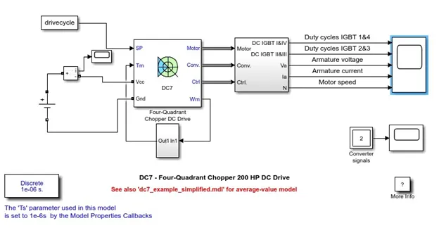
The input of the dc voltage source is 100V.The vehicle should have a reference speed.Therefore the new drive cycle is prepared in the excel sheet.
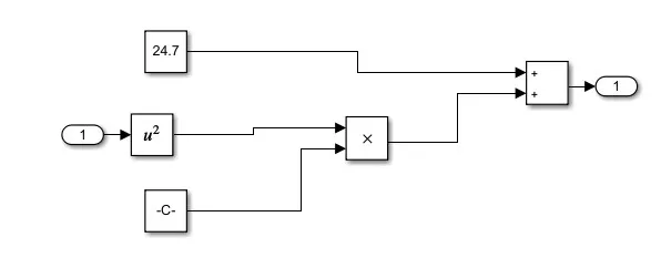
The vehicle torque equation is
T= 24.7+0.0051w^2
This equation is added in fundamental block with subsystem
SIMULATION RESULT:
RESULT:
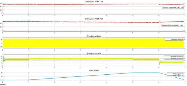
- The duty cycle of IGBT 1&4 and 2&3 are identical.
- Both the pairs are mirror image of each other.
- The reference and DC7 speed are coinciding with each other and behaving as per drive cycle.
STUDY 4:
A Brushless DC motor is an electronically commutated dc motor which does not have brushes. The permanent magnet is used which rotate around fixed armature and overcome the problem of connecting the current to armature.The controller provides pulses of current to the motor windings which control the speed and torque of the synchronous motor.
WORKING:
BLDC motor works on the principle similar to that of a Brushed DC motor. The Lorentz force law which states that whenever a current carrying conductor placed in a magnetic field it experiences a force. As a consequence of reaction force, the magnet will experience an equal and opposite force. In the BLDC motor, the current carrying conductor is stationary and the permanent magnet is moving.
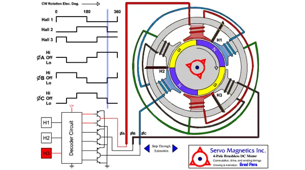
When the stator coils get a supply from source, it becomes electromagnet and starts producing the uniform field in the air gap. Though the source of supply is DC, switching makes to generate an AC voltage waveform with trapezoidal shape. Due to the force of interaction between electromagnet stator and permanent magnet rotor, the rotor continues to rotate.
With the switching of windings as High and Low signals, corresponding winding energized as North and South poles. The permanent magnet rotor with North and South poles align with stator poles which causes the motor to rotate.The working of BLDC motor is shown below.
RESULT:
Thus the operation of BLDC motor is explained clearly with working model.