Week 7 State of charge estimation
AIM:
- Simulate the 3 test cases from harness dashboard and write a detailed report on the results
- What is coulomb counting? Refer to the above model and explain how BMS implements coulomb counting for SOC estimation?
EXPLANATION:
STUDY 1:
TEST HARNESS DASHBOARD
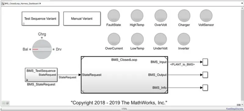
TEST CONDITION 1:
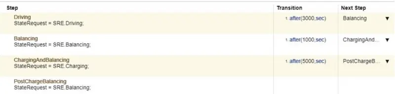
Initially when the simulation starts the model is in driving condition. After 3000sec the model moves to standalone condition. The standalone condition last up to 1000sec. After 1000sec the model will be in charging condition. Now by running the simulation.
OUTPUT:
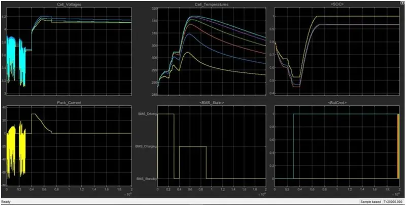
- Initially the cell voltage fluctuates during the driving state. The pack current flows in the negative direction during driving state and comes to zero in the standalone state. Both the cell voltage and pack current fluctuates till 3000sec.
- Between 4000 to7000sec constant current constant voltage charging takes place. During standby condition the pack current and voltage remains same. When the BMS operates in the charging condition the CC charging takes place. The pack current remains constant until the pack voltage reaches a maximum of 4.2V. When the pack voltage reaches the maximum voltage and remains constant while the pack current gets decreases until the battery operates in the battery state. This is called constant voltage charging.
- The battery SOC decreases during driving condition and gets increases to 100% during charging condition.
- The cell temperature ranges from 290K to 315K. The battery cell temperature get increases during driving and decreases during charging.
TEST CONDITION 2:

The driving state is maintained till 10000sec. After 10000sec the charging state takes place.
OUTPUT:
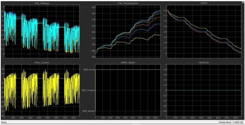
- The battery is in driving condition so the pack voltage and pack current gets fluctuated. The cell voltage gets decreases from 3.9V.
- The SOC get decreases from 80% to 0% at the time 8692sec.
- The cell temperature increases from 288K to 323K. As the current get increases the battery temperature gets increases.
- The Cell balancing is idle in this time period.
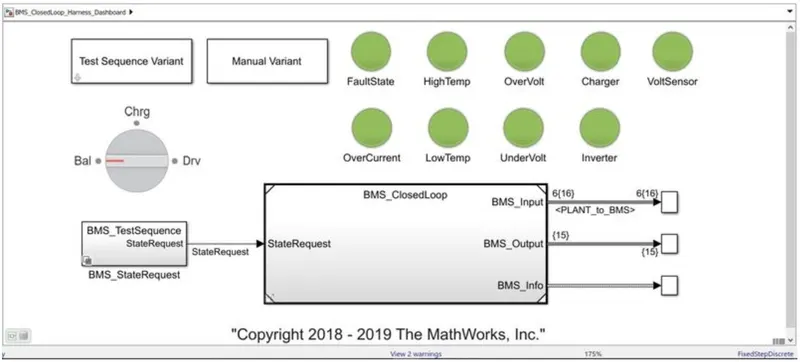
There is no fault observed from the dashboard as the dashboard shows green color.
TEST CONDITION 3:

The model runs to charging condition till the end of simulation.
OUTPUT:
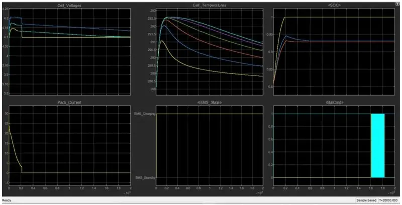
- The BMS operates in the charging mode till the end of the simulation.
- The pack current and cell voltage undergoes a constant voltage charging. The pack voltage remains constant while the pack current discharges from 24A to 0A at the end of 0.2sec.
- The SOC increases from 80% to 100% in the charging mode.
- The cell temperature gradually increases and then decreases as the pack current get discharges fully at the end of 0.2sec and remains zero till the end of the simulation
- The cell balancing takes place in the charging mode.
RESULT:
Thus the BMS model along with the three harness dashboard test cases has been simulated and results are obtained.
STUDY 2:
COULOMB COUNTING METHOD
The Coulomb counting method measures the discharging current of a battery and integrates the discharging current over time in order to estimate SOC. Coulomb counting method is done to estimate the SOC(t) , which is estimated from the discharging current, I(t), and previously estimated SOC values, SOC(t-1). SOC is calculated by the following equation:
`SOC(t)=SOC(t-1)+(I(t))/Q_n*Deltat`
The flowchart explains the algorithm used to manage the battery monitoring by switching from a battery operating mode to another in accordance with the transitions conditions.
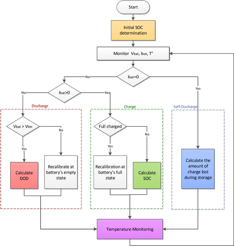
The estimation of the SOC of a Li-Ion battery in this method is based on monitoring both the voltage Vbat and the current Ibat. The operation mode of the battery is recognized by the direction of current through the battery system.When the battery is in open circuit mode, Ibat=0 and compensation of self-discharge losses will be taken into account.The information needed to carry monitoring are the measurement of the battery voltage, the current flowing through it and the operating temperature. Coulomb counter ∆Q is used to track the SOC when the battery is charged or discharged. The amount of charges ∆Q in an operating period `tau` is obtained by a temporal integration of a measured charging/discharging current Ibat.
`DeltaQ=int_t^(t+tau)I_(bat) dt`
This variance ∆Q that will be used in the following equations is negative if the battery is in discharge, positive if in charge.
COULOMB COUNTING METHOD BLOCK
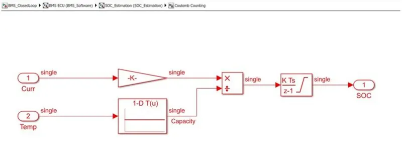
It accepts two signals current and temperature. The current signal is given to the gain block whereas the temperature signal is given to battery time and current lookup table. Both blocks are linked to split block and the output of the signal is sent to the discrete time integrator to track the charge which then aids to calculation of SOC. The positivity of the method is the easy to implement and cheap.
The drawback of the coulomb counting method is an accumulation of current sensor error and inability to recover from the wrong initial condition because of lack of feedback from voltage measurement.
RESULT:
Thus the coulomb countingmethod has been explained with implementation in the BMS model has been done successfully.