EV Drivetrain
AIM:
- Which types of power converter circuits are employed in electric and hybrid electric vehicle?
- An Electric Vehicle's powertrain with 72V battery pack in shown in the diagram below. The duty ratio for acceleration operation is 'd1' and for the braking operation the duty ratio is 'd2'.
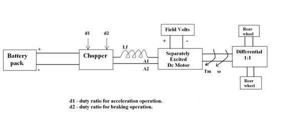
The other parameters of the electric vehicle is given below,
Motor and Controller Parameters:
Rated Armature voltage= 72 V
Rated armature current= 400 A
Ra= 0.5Ω, KΦ= 0.7 Volt second
Chopper Switching frequency= 400 Hz
The vehicle speed-torque characteristics are given by the below equation
What is EV steady state speed if duty cycle is 70%?
- Refer to the blog on below topic:
Induction Versus DC brushless motors by Wally Rippel, Tesla
Explain in brief about author’s perspective.
STUDY 1:
The power electronics deals with the process and control the flow of electrical energy by supplying voltage and current in a form that is optimally suited for user load.
A power electronic converter uses power electronic components such as SCRs, TRIACs, IGBTs, etc. to control and convert the electric power. The main aim of the converter is to produce conditioning power with respect to a certain application.
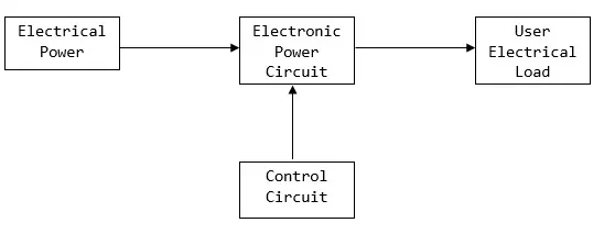
The power electronic circuit consists of both power part and control part. Power part transfers the energy from source to load and it consists of power electronic switches (SCR or TRIAC), transformers, electric choke, capacitors, fuses and sometimes resistors.
The control circuit or block regulates the elements in the power part of the converter. This block is built with a complex low power electronic circuit that consists of either analog or digital circuit assembly.
Power electronic converters perform various basic power conversion functions. This converter is a single power conversion stage that can perform any of the functions in AC and DC power conversion systems.
APPLICATION:
Power electronic converters are used everywhere in normal daily routines at home, commercial workplaces or in an industrial environment.
Due to the high power handling with higher efficiencies, these converters become an integral part of industrial electric drives, high electric power supplies, electric traction systems and automobile control equipments.
There are different types of power electronic converters used for performing different functions (such as inversion, rectification, etc.) which are rated from a few milliwatts to a few thousand watts.
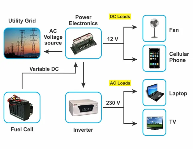
TYPES OF POWER CONVERTER:
Power electronics are classified based on the type of function performed.They are categorized into following types.
- AC to DC= Rectifier: It converts AC to unipolar (DC) current
- DC to AC= Inverter: It converts DC to AC of desired frequency and voltage
- DC to DC= Chopper: It converts constant to variable DC or variable DC to constant DC
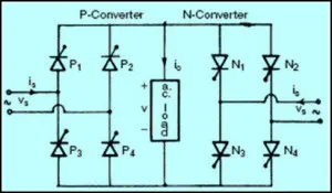
- AC to AC= Cycloconverter, Matrix converter: It converts AC of desired frequency and/or desired voltage magnitude from a line AC supply.
AC to DC Converters or Rectifiers
The AC to DC converter is also called a rectifier, which converts AC supply from main lines to DC supply for the load. The essential components in this rectifier include transformer, switching unit, filter and a control block.
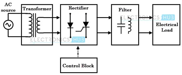
- The transformer adjusts the primary AC source supply to the input of rectifier stage. Usually it is a step-down transformer that reduces the supply voltage to a circuit operating range.
- The rectifier converts the low voltage AC supply into DC supply.
- It comprises diode and/or thyristors based on type of rectifier. The output of the rectifier is of pulsed DC and hence it is filtered using filter circuit, which is usually made with a capacitor or a choke.
- The control block controls the firing angle of thyristors in case of phase controlled rectifiers. Since the diode is not a controllable device, control block is not needed in case of diode rectifiers.
- Rectifiers are majorly classified into two types namely Uncontrolled diode rectifiers and Controlled rectifiers.
DC to AC Converters or Inverters
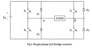
The DC-AC converters convert the input DC power into AC power. These converters are also known as inverters. There are a lot of different types of inverters; however, a typical Inverter uses four switches or thyristors. The four switches make 2 pairs, individually controlled by a switching circuit where each pair is switched on at one interval of time. This alternating switching of the thyristors provides an alternating current through the load. This rhythm of turning the switches changes the DC voltage into AC across the load. The output voltage of the circuit can be directly controlled by changing the conduction time of the switch using the switching circuit.
DC TO DC CONVERTER
- A DC chopper is a static device that converts a fixed input DC voltage to variable DC output or a fixed DC output of different magnitude (which can be lower or higher) than input value.
- The chopper circuit is connected between DC input source and DC load. This chopper consists of power electronic switching devices such as thyristors which are connected in such a way that they produce required DC voltage to the load.
- The output voltage is controlled by adjusting ON time of the thyristor (or switch) which turn changes the width of DC voltage pulse at the output. This method of switching is called as pulse width modulation (PWM) control.
- The output of the chopper can be less or greater than the input and also it can be fixed or variable. These can be unidirectional or bidirectional devices based on the application.
- DC choppers are mainly used in DC drives, i.e., electric vehicles and hybrid electric vehicles.
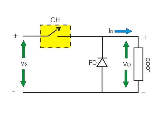
DC choppers are classified into three basic types based on input and output voltage levels
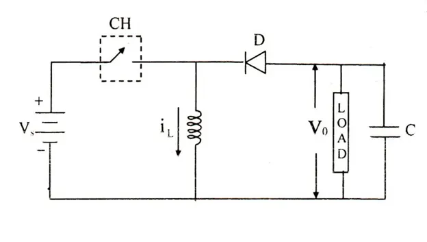
- Step down chopper or buck converter
- Step up chopper or boost converter
- Buck boost converter
Step-down Chopper or Buck converter
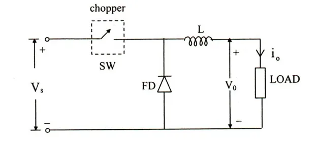
- A step-down chopper produces an average output voltage lower than the input DC voltage.
- The output voltage is equal to (TON / T) Vin. So, by controlling the duty ratio K = (TON / T), the output voltage will be increased.
Step-up Chopper or Boost converter
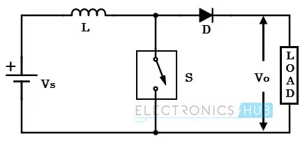
- A Step up chopper produces the output voltage higher than the input voltage.
- The output voltage is equal to (1/ 1 – d) times the input voltage, where d is the duty ratio (TON / T). By varying this duty ratio, the output voltage will be varied till the load gets desired voltage.
BUCK BOOST CONVERTER
- This chopper can be used both in step-down and step-up modes by continuously adjusting its duty cycle.
- By varying the value of duty ratio to a certain value, the output voltage is lower than the input voltage, typically in the range 0 ≥ k > 0.5, thus buck converter.
- The output is higher than the input voltage if the duty ratio is in the range of 0.5 > K ≥ 1, thus acts as a boost converter.
 AC to AC CONVERTERS
- The AC converters connect an AC source to AC loads by controlling amount of power supplied to the load.
- This converter converts the AC voltage at one level to the other by varying its magnitude as well as frequency of the supply voltage.
- These converters convert the fixed AC source into variable AC output voltage.
- There are two types of AC-AC Converter a
- Matrix converter
- Cyclo converter
CONCLUSION:
Thus the power converters employed in the electric and hybrid electric vehicle are explained clearly.
STUDY 2:
Given data:
Armature Voltage = 72V
Armature Current = 400A
Armature Resistance = 0.5ohm
Motor Constant(KØ) = 0.7V
Chopping Frequency = 400Hz
Duty cycle =70
Vehicle Speed Torque Characteristics:
Tv = 24.7+(0.0051)w^2………(1)
Motor Speed Torque Characteristics:
Tm = (V*KØ/Ra) – (( KØ)^2/Ra)*w)…….(2)
To Find Average voltage
Avg.Voltage = Voltage *Duty cycle/100
= 72 * 70/100
= 72*0.7
= 50.4V
Tm = (50.4*0.7/0.5) – (0.49/0.5).w
Tm = 70.56 – 0.98w…………………..(3)
Equating (1) and (3)
24.7 + (0.0051)w^2 = 70.56 – 0.98w
0.0051w^2 + 0.98w – 45.86 = 0….......(4)
On solving the above equation and neglecting the negative values
w = 38.91 rad/s
CONCLUSION:
Thus the steady state speed for EV with duty cycle of 70% is 38.91 rad/s
STUDY 3:
There is no best choice when it comes to engines.The choice of engine will vary according to performance and application.The same is true for electric drives.Brushless dc drives and AC Induction drives are the two main drives in EV.Both has its own advantage and disadvantage.
The Brushless dc and Induction drive uses motor having similar stator.They both uses a 3phase modulating control.The only difference is the rotor and inverter control and with digital controllers the only difference are with control code.
|
Induction motors |
DC Brushless motor |
|
Nikola Tesla first found the induction motor |
Wally Rippel first found the DC Brushless motor |
|
No need of permanent magnet |
Permanent magnet is used in rotor |
|
It requires speed sensor |
It requires absolute position sensor |
|
Best power factor is 85% |
It can operate at unity power factor |
|
The heat generated by the rotor is more so that cooling of rotor is quite difficult. |
The heat generated by rotor is less so that cooling of rotor is easier. |
|
Losses does not necessary grow as the machine grows |
Losses increases as the machine grows |
|
Cost is low as there no need of permanent magnet. |
Cost is high as the permanent magnet is used in rotor |
|
Induction motor are difficult to control as the control laws are more complex and difficult to understand. |
Brushless DC motor are easy to control compared to induction motor. |
|
Achieving stability is difficult |
Achieving stability is easier compared to Induction motor. |
CONCLUSION:
DC brushless drives will likely continue to dominate in the hybrid and coming plug-in hybrid markets.Induction drives will likely maintain dominance for the high-performance pure electrics.Both as its own advantage and disadvantage. In future we can see both DC and Induction drives used in the hybrid and electric vehicle.