Design of gear shift logic and Washing machine
AIM:
To implement a simulink chart for the “GEAR LOGIC” as per conditons below
SPEED RANGE GEAR
0 – 15 1
16 – 25 2
26 – 40 3
41 – 60 4
Above 61 5
OBJECTIVE:
To generate the gear shift transmission at various speed.
SIMULINK MODEL:
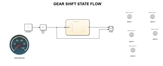
GEAR STATE FLOW
- The slider gain is given as input which determines the speed.The variation of the slider gain is displayed using circular valve.
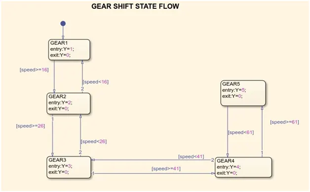
- The output of the slider gain is connected to the chart. The gear shift control logic is determined in chart in the form of state flow.
- Each gear is specified for the particular speed.In order to obtain the particular speed the gear should be changed.
- The changes in gear are displayed using lamp.
- Initially the slider gain is 0. When we increase the speed, the input is given to state flow chart where it checks the input speed and displays the gear number.
- According to the given data speed range and gear are shown below.
- At 1st gear the speed range is 0 – 15 kmph
- At 2nd gear the speed range is 16 – 25 kmph
- At 3rd gear the speed range is 26 – 40 kmph
- At 4th gear the speed range is 41 – 60 kmph
- At 5th gear the speed range is Above 61 kmph
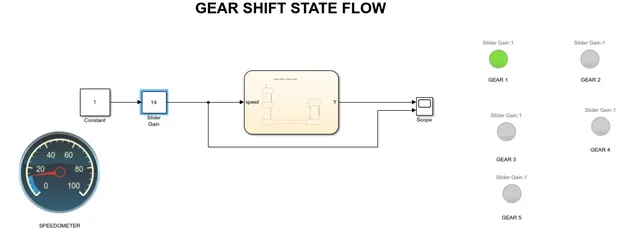
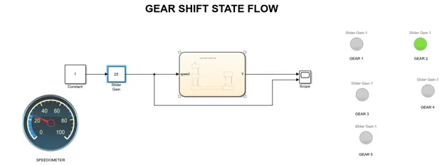
- Depends upon the input speed the gear is displayed.
- Input speed of the slider gain is 14 the GEAR 1 is activated.
- GEAR 2 is activated as the input speed is 25
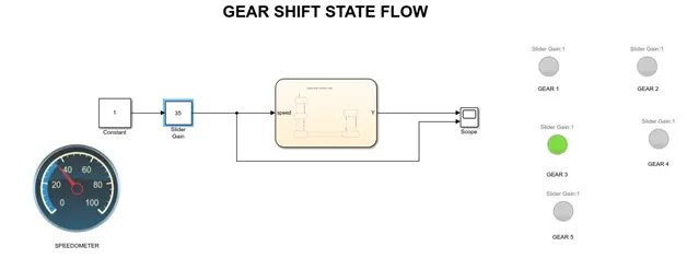
- GEAR 3 is activated as the input speed is 35
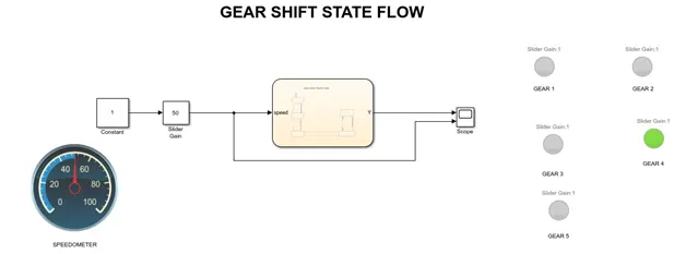
- GEAR 4 is activated as input speed is 50
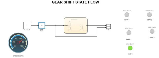
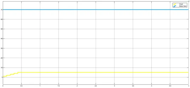
- GEAR 5 is activated as input speed is 70
SIMULINK OUTPUT:
RESULT:
Thus the design of gear shift transmission at various speed are obtained and results are displayed.
AIM:
To design a control logic for Washing Machine using simulink model.
OBJECTIVE:
To generate the model for washing machine at various state condition.
THEORY:
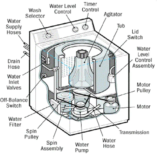
A Washing Machine is a device which is used to wash various types of clothes without any physical effort.It has different states such as rinsing,washing,soaking and drying.It works on the principle of centrifugal force.
SIMULINK MODEL:
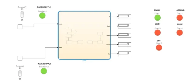
WASHING MACHINE STATE FLOW
EXPLANATION:
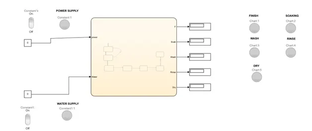
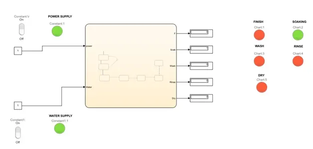
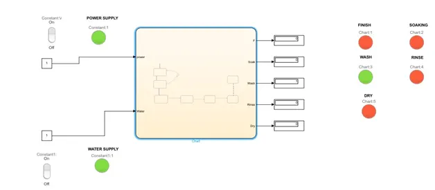
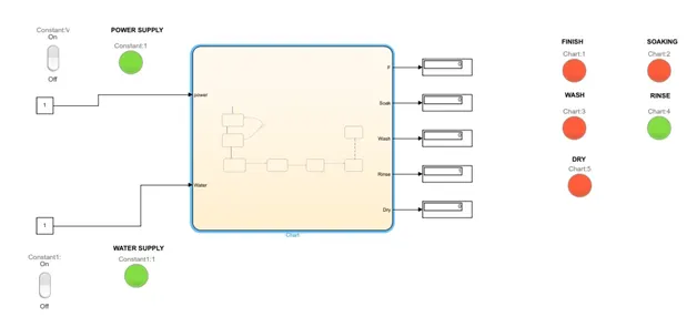
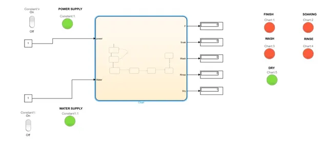
- The power supply and water supply are given to the machine and are indicated by constant value 0 and 1.
- The rocker switch and lamp are activated according to the condition of the power supply and water supply.
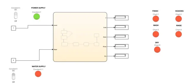
- The red color indicates that condition is OFF state while the green color indicates the condition is ON state.
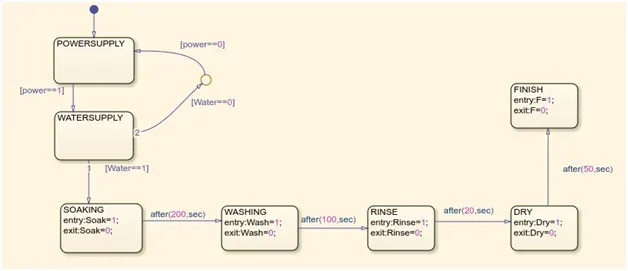
- Initially the signal is process to flow chart, the power supply is ON while the water supply is OFF .The machine is not started as the water supply is not activated.
- The water supply is ON and machine is activated.
- The Soaking process takes place with time duration of 200sec followed by washing time of 100sec
- The Rinsing process takes place for next 20sec follwed by a dryer of 50sec.
- After the completion of all tasks the machine is turn off.
- The Finish lamp indicates the green when the process is completed.
INITIALLY POWER SUPPLY IS ON AND WATER SUPPLY IS OFF
SOAKING PROCESS
WASHING PROCESS
RINSING PROCESS
DRYING PROCESS
FINISH
After completion of all process the Finish lamp is displayed by showing green color.
RESULT:
Thus the design of washing machine at various states is done successfully.