Final Project: Design of an Electric Vehicle
AIM: To create a MATLAB model of electric car which uses a battery and a DC motor. To choose suitable blocks from Powertrain block set and prepare a report about the model.
OJECTIVES:
- System level configurations
- Model parameters
- Results
- Conclusion
INTRODUCTION
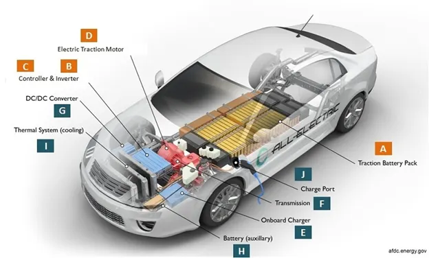
An electric vehicle uses one or more electric motor for propulsion instead of using petrol, diesel or buring gases. Depending on the type of vehicle, motion may be provided by wheels or propellers driven by rotary motors or in the case of tracked vehicles by linear motors. Electric vehicles can include electric cars, electric train, electric lorries, electric boat,electric motorcycle and scooters.
An electric car is an alternative fuel automobile that uses electric motors and motor controllers for propulsion, in place of more common propulsion methods such as the internal combustion engine (ICE). Electricity can be used as a transportation fuel to power battery electric vehicles (EVs). EVs store electricity in an energy storage device such as a battery. The electricity powers the vehicle's wheels via an electric motor. EVs have limited energy storage capacity which must be replenished by plugging into an electricity.
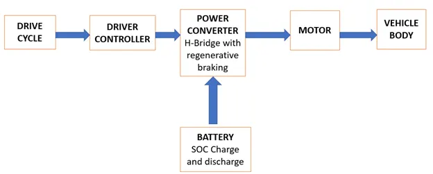
BLOCK DIAGRAM:
SIMULATION MODEL:
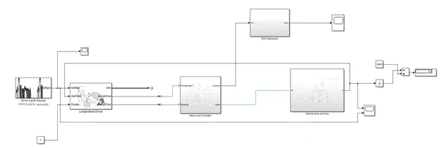
SYSTEM LEVEL CONFIGURATION
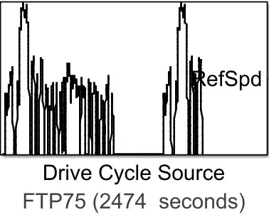
DRIVE CYCLE SOURCE:
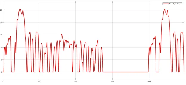
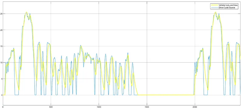
The drive cycle is a series of points representing the speed of the vehicle with respect to time.In this project we use FTP75 drive cycle source.The drive cycle run upto 2474sec i.e 41min 23sec.The output of the drive cycle is given to the vehicle reference in the longitudinal driver.
LONGITUDINAL DRIVER
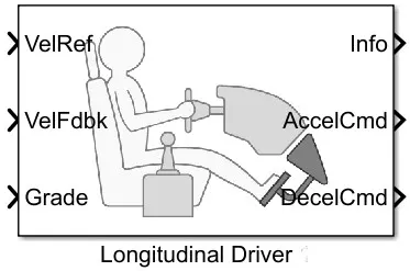
The Longitudinal driver block implements a longitudinal speed controller.Based on reference and feedback velocities,the block generates normalized acceleration and braking commands that can vary from 0 through 1.It is used for model the dynamic response of a driver or generate command necessary to track longitudinal drive cycle.
The FTP75 drive cycle is given as input to the vehicle reference in longitudinal driver.
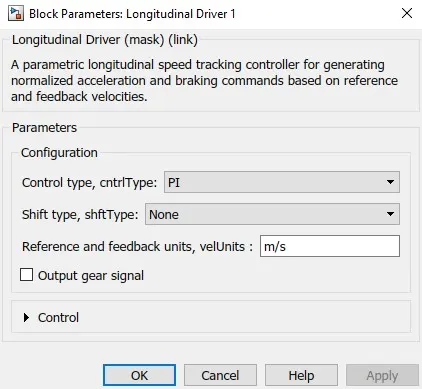
The type of controller used in longitudinal driver is PI.The reference and feedback velocities are in m/s.
MOTOR AND CONTROLLER SUBSYSTEM
Controlled Voltage Source
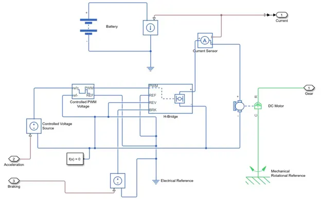
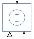
The controlled voltage source block is used to maintain specific voltage at its output regardless of the current flowing through it.The block has one physical signal input port looks like triangle and two electrical ports associated with terminals.The output voltage is V=Vs where Vs is the numerical value represented at physical port.
The longitudinal driver produces acceleration and braking command are given as input to the physical port of the controlled voltage source block.
Controlled PWM Voltage
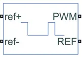
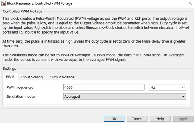
This block used to produce PWM voltage which drives the H-bridge motor drive.The positive terminal of reference voltage is connected to the controlled voltage source whereas the negative terminal is connected to the ground.It produces output voltage depends upon the input pulse.When the input pulse is low the output is zero whereas the input pulse is high then the output is also high.The output of the pwm port is connected to the H-bridge.
The Simulation mode can be set to PWM or Averaged. In PWM mode, the output is a PWM signal. In Averaged mode the output is constant with value equal to the averaged PWM signal.
H-Bridge motor drive
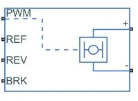
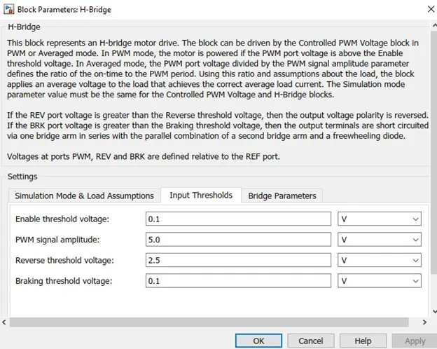
This block produces a controlled voltage depends upon the input signal at the PWM port.If the input signal has a value greater than Enabled Threshold voltage value then the output voltage is produced and has values equal to the output voltage amplitude parameters.If it has value less than the Enabled Threshold voltage value then block maintains the load current via one semiconductor switch and one freewheeling diode.
The signal at the REV port determines the polarity of the output. If the value of the signal at the REV port is less than the value of the Reverse threshold voltage parameter, the output has positive polarity; otherwise, it has negative polarity.
DC MOTOR
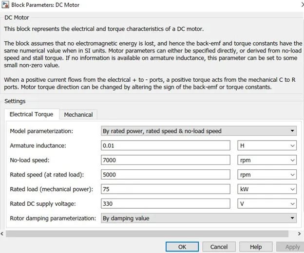
This block consists of electrical and mechanical parts.The electrical parts are stationary whereas the mechanical parts are rotational denoted as blue and green.It represents the electrical and torque characteristics of dc motor.
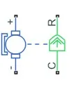
The positive terminal of electrical port is connected to the H-bridge motor drive through current sensor whereas the negative terminal is connected to the ground.The mechanical port R is connected to the gear and port C is connected to mechanical rotational reference.
When a positive current flows from the electrical + to - ports, a positive torque acts from the mechanical C to R ports. Motor torque direction can be changed by altering the sign of the back-emf or torque constants.
Current Sensor

This block converts current measured in any electrical branch into a physical signal proportional to the current.The positive and negative port are connected to the H-bridge and DC motor while the physical port I is the output signal is connected to the controlled current source.
BATTERY
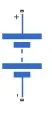
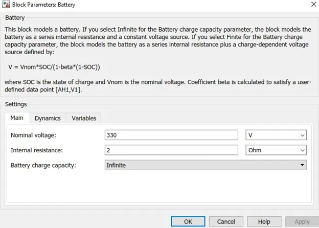
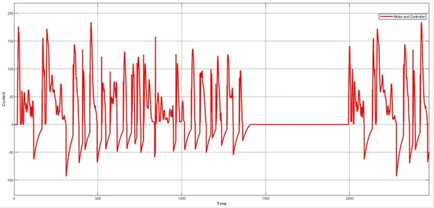
A battery is a device which stores the electric current.It powers the electric motor in the electric vehicle.The battery capacity voltage is 330V.The output of the battery is connected to the controlled current source where it produces specific current regardless of the voltage flowing across it.
BATTERY SOC CALCULATION

Rate Transition
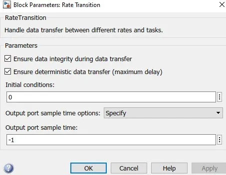
The Rate Transition block transfers data from the output of a block operating at one rate to the input of a block operating at a different rate.
GAIN
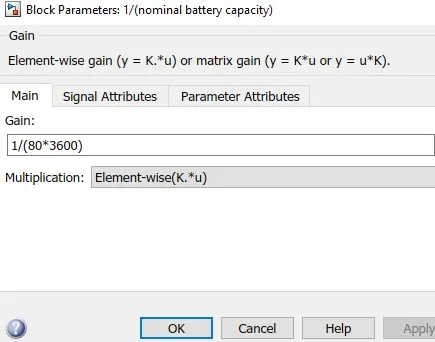
This block used to multipy the input with constant value.The battery rating is 80kw.The battery rating value is multiplied with the 3600sec.
Discrete Time Integrator
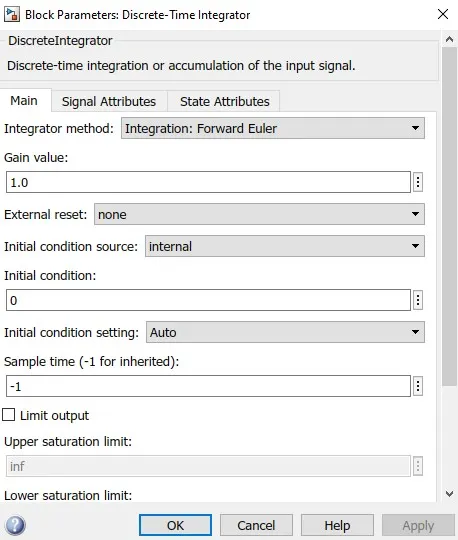
This block is used to integrate the input signal to produce the purely discrete time model.
VEHICLE BODY AND TIRES SUBSYSTEM
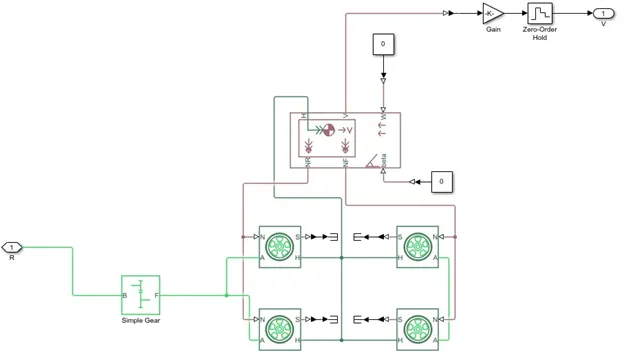
Simple Gear
The motor output is given to the input of the bear at gear.The follower gear F is connected to the axle of the tire.
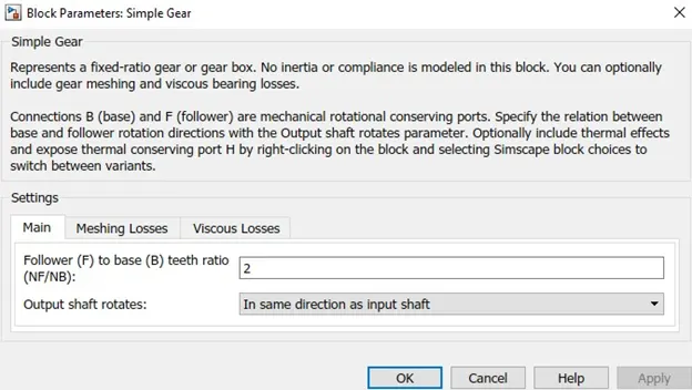
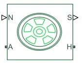
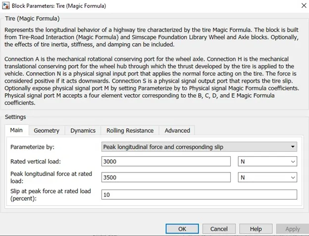
TIRE BLOCK
The Tire block models the tire as a rigid wheel-tire combination in contact with the road and subject to slip. When torque is applied to the wheel axle the tire pushes on the ground (while subject to contact friction) and transfers the resulting reaction as a force back on the wheel. This action pushes the wheel forward or backward.
VEHICLE BODY
The Vehicle Body block represents a two-axle vehicle body in longitudinal motion. The vehicle can have the same or a different number of wheels on each axle. The block accounts for body mass, aerodynamic drag, road incline, and weight distribution between axles due to acceleration and road profile. Optionally include pitch and suspension dynamics. The vehicle does not move vertically relative to the ground.
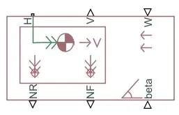
Output Port
V represents the vehicle longitudinal velocity of the physical signal output port.
NF represents the normal force on the front wheel in physical signal output port.Wheel forces are positive if acting in downwards.
NR represents the normal force on the rear wheel in physical signal output port. Wheel force are positive if acting in downwards.
Conserving Port
H represents the mechanical translational conserving port associated with the horizontal motion of the vehicle body.
Input Port
W represents the input physical port for headwing speed
beta represents the input physical port for inclination speed
Distance calculation
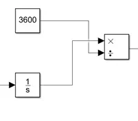
The velocity is given to the integrator block and divided by 3600 so that distance travelled can be found out in KM.Integrating the velocity gives distance.
MODEL PARAMETERS
| Drive Cycle | FTP75 |
| Speed | 60km |
| Rated DC Voltage | 330V |
| No load speed in rpm | 7000 |
| Full load speed in rpm | 5000 |
| Vehicle Weight in kg | 1200 |
| Frontal Area in m^2 | 3 |
| Drag Coefficient | 0.4 |
| Distance covered in km | 5.5 |
| Batttery SOC(charge left) | 86% |
| Duration of drive cycle | 2474sec |
DRIVE CYCLE OUTPUT
The maximum speed attained in the FTP45 drive cycle is 25m/s i.e 90kmph.
BATTERY CURRENT
The battery has a voltage of 330V and internal resistance of 0.2ohm.
BATTERY SOC :
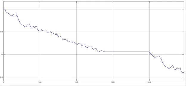
The battery state of charge represents the battery capacity left for vehicle after being used.The battery capacity reduces from 100% to 86%.Regenerative braking takes place as the battery charge get increased.
CONCLUSION:
The simple and small distance coverage of electric vehicle is designed.The distance covered by electric vehicle is 5.5km with the battery rating of 80kwh using FTP45 drive cycle.The battery state of charge reduces from 100 to 86%.The distance covered by electric vehicle can be increased by increasing the battery rating capacity.