Project 1 Mechanical design of battery pack
AIM:
To prepare the detailed battery pack drawing along with its enclosure using cell ANR26650M1-B cylindrical cells of pack capacity 18kwh.
EXPLANATION:
A battery consists of one or more electrochemical cells (battery cells) which are converting chemical energy into electrical energy (during discharging) and electrical energy into chemical energy (during charging).The individual cells are connected in the various combination of series and parallel connections in order to get the desired battery characteristics.
The high voltage battery it is one of the most important component of a battery electric vehicle (BEV). The battery parameters have a significant influence on other components and attributes of the vehicle, like:
- maximum traction motor torque
- maximum regeneration brake torque
- vehicle range
- vehicle total weight
- vehicle price
A battery pack is a set of any number of (preferably) identical batteries or individual battery cells. They may be configured in a series, parallel or a mixture of both to deliver the desired voltage, capacity, or power density. Components of battery packs include the individual batteries or cells, and interconnects which provide electrical conductivity between them. Rechargeable battery packs often contain a temperature sensor, which the battery charger uses to detect the end of charging.
An advantage of a battery pack is the ease with which it can be swapped into or out of a device. This allows multiple packs to deliver extended runtimes, freeing up the device for continued use while charging the removed pack separately. Another advantage is the flexibility of their design and implementation, allowing the use of cheaper high-production cells or batteries to be combined into a pack for nearly any application. At the end of product life, batteries can be removed and recycled separately, reducing the total volume of hazardous waste.
The high voltage battery it is one of the most important component of a battery electric vehicle (BEV). The battery parameters have a significant influence on other components and attributes of the vehicle, like:
- maximum traction motor torque
- maximum regeneration brake torque
- vehicle range
- vehicle total weight
- vehicle price
Pretty much all major aspects of a pure electric vehicle (EV) depend on the parameters of the high voltage battery.
For our electric vehicle battery design we are going to start from 4 core input parameters:
- chemistry
- voltage
- average energy consumption of the vehicle on a driving cycle
- vehicle range
A battery cell consists of five major components: electrodes – anode and cathode, separators, terminals, electrolyte and a case or enclosure. For automotive applications there are different types of cells used.
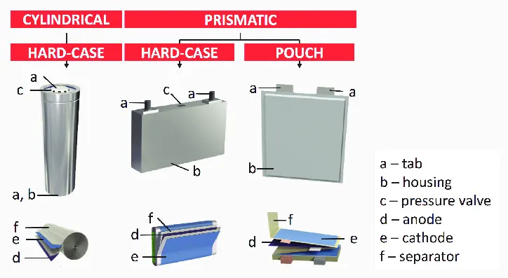
Individual battery cells are grouped together into a single mechanical and electrical unit called a battery module. The modules are electrically connected to form a battery pack. There are several types of batteries (chemistry) used in hybrid and electric vehicle propulsion systems but we are going to consider only Lithium-ion cells. The main reason is that Li-ion batteries have higher specific energy [Wh/kg] and specific power [W/kg] compared with other types.
The voltage level of the battery determines the maximum electrical power which can be delivered continuously. Power P [W] is the product between voltage U [V] and current I [A]:
P=U⋅I
The higher the current, the bigger the diameter of the high voltage wires and the higher the thermal losses. For this reason, the current should be limited to a maximum and the nominal power obtained by having a higher voltage.
Battery pack architectures
All high voltage battery packs are made up from battery cells arranged in strings and modules. A battery cell can be regarded as the smallest division of the voltage.
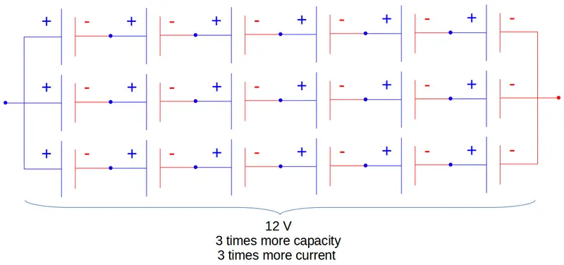
Individual battery cells may be grouped in parallel and / or series as modules. Further, battery modules can be connected in parallel and / or series to create a battery pack. Depending on the battery parameters, there may be several levels of modularity.
The total battery pack voltage is determined by the number of cells in series. For example, the total (string) voltage of 6 cells connected in series will be the sum of their individual voltage.

In order to increase the current capability the battery capacity, more strings have to be connected in parallel. For example, 3 strings connected in parallel will triple the capacity and current capability of the battery pack.
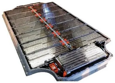
The example is the high voltage battery pack of Tesla Model S, which has:
- 74 cells in a parallel group
- 6 groups in series for a module
- 16 modules in series
- 7104 cells in total
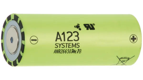
CELL USED IN DATA SHEET
ANR26650M1-B cells manufactured by A123 system were used for the battery pack. A123’s high-performance Nanophosphate lithium iron phosphate (LiFePO4) battery technology delivers high power and energy density combined with excellent safety performance and extensive life cycling in a lighter weight, more compact package. Our cells have low capacity loss and impedance growth over time as well as high usable energy over a wide state of charge (SOC) range, allowing our systems to meet end-of-life power and energy requirements with minimal pack oversizing.
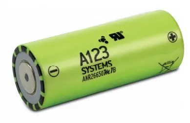
CELL DATA:
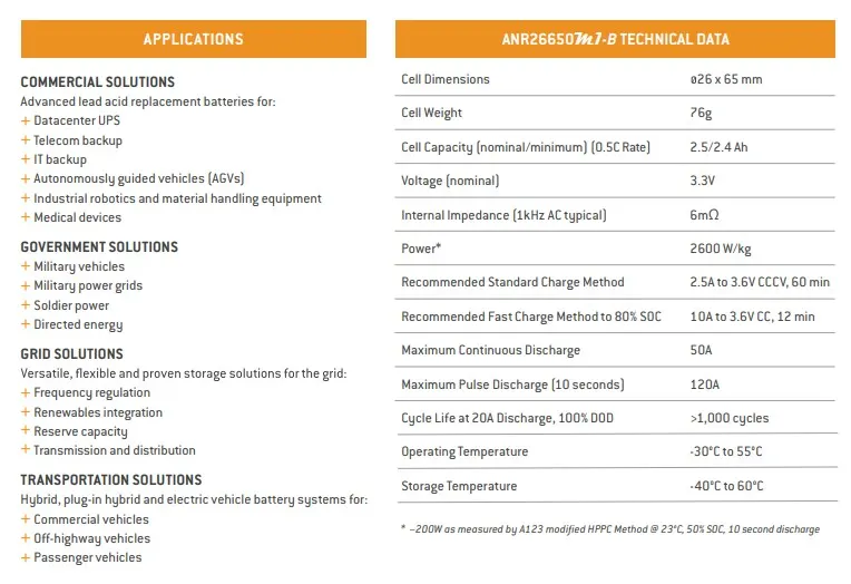
CELL CALCULATIONS:
Volume of cell = `pi`*`r^2`*h
= 3.14*(0.013)^2*0.065
= 0.0345m^3
The volume of cell is 0.0345m^3
Cell energy = Nominal cell capacity*Nominal cell voltage
= 2.5*3.3
= 8.25Wh
The cell energy is 8.25Wh
Cell energy density = cell energy/cell volume
= 8.25/0.0345
= 239.13(Wh/m^3)
The cell energy density is 239.13(Wh/m^3)
BATTERY PACK ASSUMPTIONS
- There are 46 series cells and 48 parallel cells in battery pack
- All are ANR 26650m1-B cells
BATTERY PACK CALCULATIONS
The total number of cells is calculated as the product between the number of cells in series and the number of cells in parallel.
Total number of cells = 46*48
= 2208 cells
The total number of cells is 2208
The voltage of battery pack is calculated as the product between nominal voltage of cell [V] and number of cells connected in series.
Voltage of battery pack = nominal voltage *number of cells in series
= 3.3*46
= 151.8V
The voltage of battery pack is 151.8V
The current of battery pack is calculated as the product between nominal current of cell [Ah] and number of cells connected in parallel.
Current of battery pack = nominal current*number of cells in parallel
= 2.5*48
= 120Ah
The current capacity of battery pack is 120Ah
Total energy of the battery pack = Voltage of battery pack * Current of battery pack
= 151.8*120
= 18.216kWh
The total energy of the battery pack is 18.216kWh
The battery pack mass (cells only) [kg] is the product between the total number of cells and the mass of each battery cell [kg]
Mass of the battery pack = Total number of cells* Mass of the single cell
= 2208*0.076
= 167.8kg
The mass of the battery pack is 167.8kg
The volume of the battery pack (cells only) [m3] is the product between the total number of cells and the mass of each battery cell [m3]. This volume is only used to estimate the final volume of the battery pack, since it does not take into account the auxiliary components/systems of the battery.
Volume of battery pack = Total number of cells *volume of the single cell
= 2208*0.0345
= 76.17m^3
The volume of battery pack is 76.17m^3
The volume can be also calculated function of number of strings and number of cells in a string. This calculation method is more appropriate for cylindrical cell, since the volume occupied by a cylindrical cell must take into account the air gap between cells.
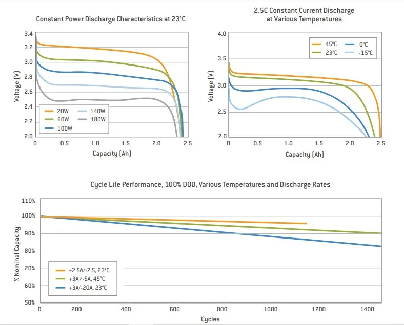
ANR26650M1-B Specifications
Nominal Ratings
Voltage: 3.3 Volts
Capacity: 2.5 Ah
Energy: 8.25 Wh
Specific Power: 2600 W/kg
Impedance (1KHz AC Typical) 6 mΩ
Cycle Life at 1C/1C, 100% DOD: > 4000 cycles
Cell Type: 26650 Lithium Ion Power Cylindrical Cell
Discharging
Max Continuous Discharge: 50 A
Max Pulse Discharge Current >50% SOC (10s): 120 A
Minimum Voltage: 2 Volts
Temperature: -30ºC to 55ºC
Charging
Recommended Standard Charge: 2.5 Amps
Max Charge Rate: 10 Amps
Max Pulse Charge Current <50% SOC (10s): 25 A
Float Voltage: 3.45 Volts
Recommended charge V & Cut-off Current: 3.6 Volts, taper to 125mA
Temperature
(reduce charging current to 250mA when under 0ºC): 0ºC to 55ºC
Mechanical
Diameter: Ø25.96 +/- 0.5 mm (1.0")
Length: 65.15 +/- 0.5 mm (2.6")
Mass: 76 g
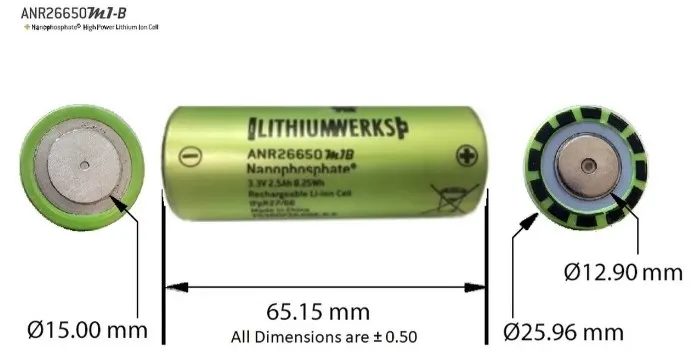
STEPS FOR DESIGNING A BATTERY PACK
STEP 1:
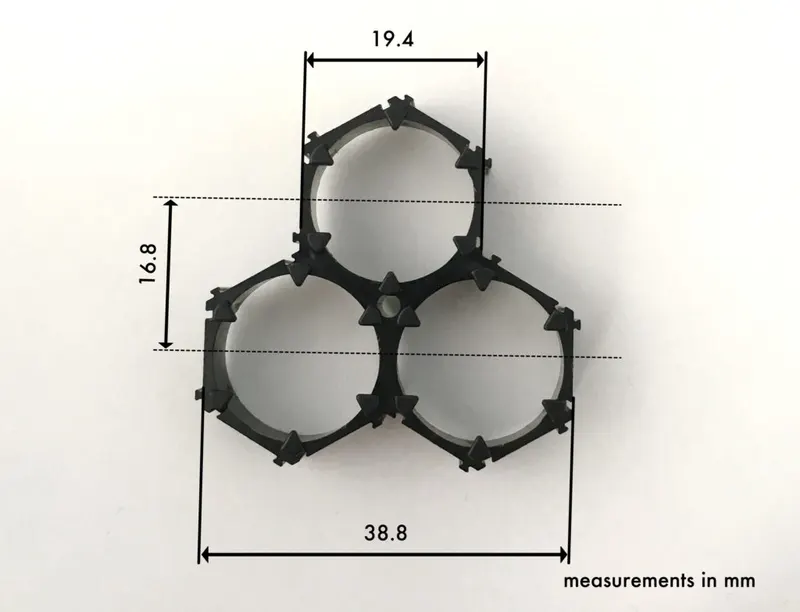
Since the battery pack is of high density we choose hexagon connectors and join them as shown below.

STEP 2:
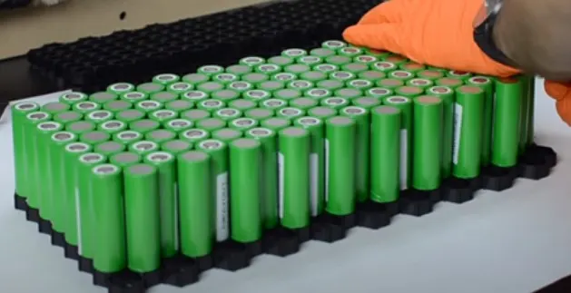
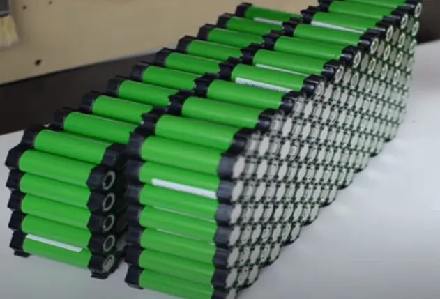
Insert the cells inside the connector with positive and negative placed alternatively in the adjacent rows.
Inserting cells inside the connectors
Insert connectors on the top and bottom
STEP 3:
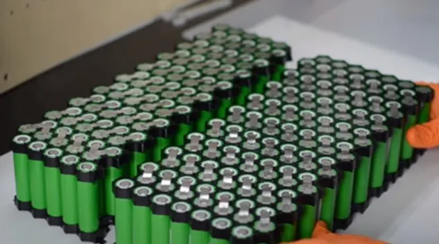
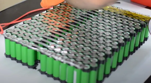
Spot weld with nickel strips to make series connections as shown below.
Make series connections of battery
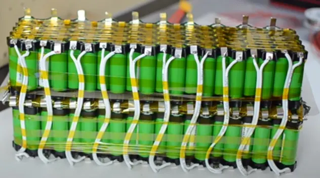
After making the series connections, connect with strings in parallel and complete the connections below.
Connect the strings in parallel
Complete connection using wires
STEP 4:
Battery management systems (BMS) are electronic control circuits that monitor and regulate the charging and discharge of batteries. The battery characteristics to be monitored include the detection of battery type, voltages, temperature, capacity, state of charge, power consumption, remaining operating time, charging cycles, and some more characteristics.
- The task of battery management systems is to ensure the optimal use of the residual energy present in a battery.
- In order to avoid loading the batteries, BMS systems protect the batteries from deep discharge, from over-voltage, which are results of extreme fast charge and extreme high discharge current.
- In the case of multi-cell batteries, the battery management system also provides for cell balancing function, to manage that different battery cells have the same charging and discharging requirements.
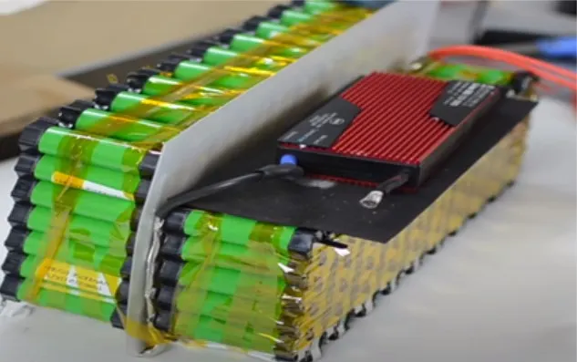
Install BMS for battery pack as shown below.
STEP 5:
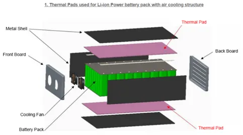
Install cooling structures for air cooling/liquid cooling as shown below
Install thermal pads for battery pack with air cooling
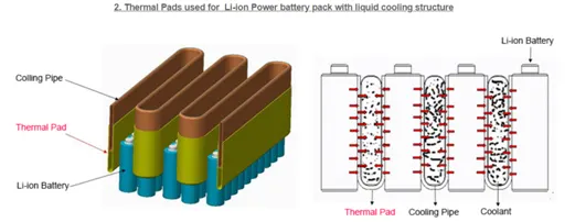
Battery pack with liquid cooling
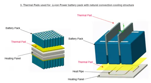
Battery pack with convection cooling
STEP 6:
Install the battery pack inside the enclosure as shown below
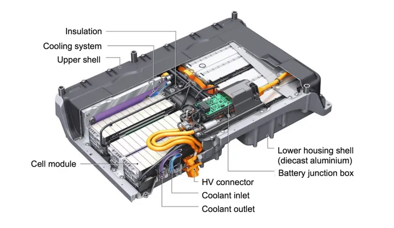
Installing the battery pack inside the enclosure
Calculating of Enclosure size
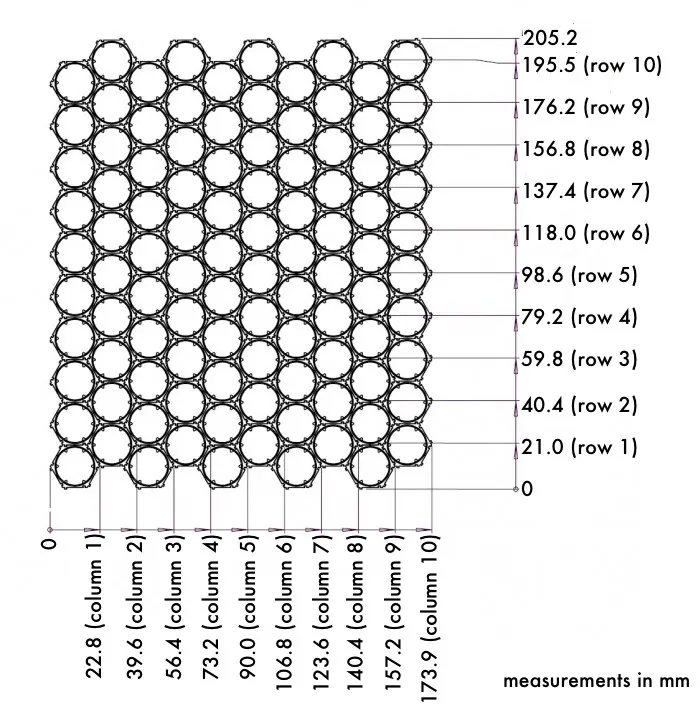
Enclosure for the battery pack
There are different types of enclosures available for the battery pack. A few are explained below. The main features required for EV battery enclosures are
- Lightweight
- Shock and Vibration-proof
- Fire protection
- Prevent Electromagnetic radiation
- Low cost
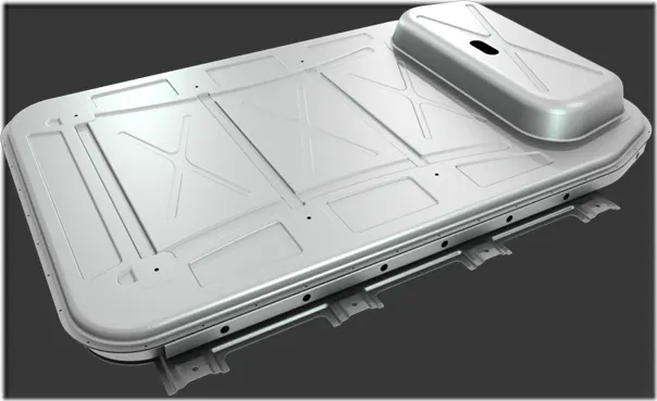
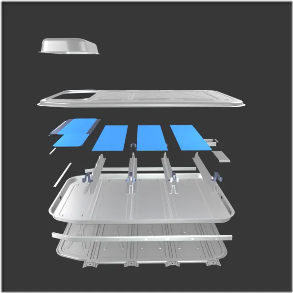
Aluminium sheet enclosure
Aluminum enclosure being more corrosion-resistant, easily recyclable and having better thermal conductivity, which helps keep battery cells cool and increases its lifespan as compared to steel designs.
The lightweight, high-strength material can help extend range, allowing vehicles to go 6-10 percent further on a single charge.
Using aluminum means the enclosure is up to 50 percent lighter than an equivalent steel design. As a result, it matches the best energy density in the industry by enabling more than 160 watt-hours per kilogram, an extremely efficient design for OEMs and Tier 1 battery pack manufacturers.
- Glass fiber based enclosure
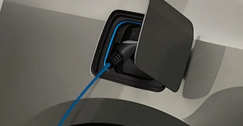
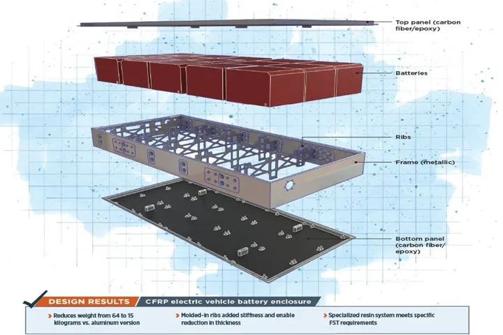
Materials made of composites are suitable for battery enclosures for different reasons. Besides their light weight, which enhances the electric vehicle’s range fiber-reinforced gas tightness and feature excellent fire protection properties. Composite materials can also help to achieve improved structural stiffness of the underbody, e.g.to protect against penetration as well as optimized thermal management. Carbon fibers are ideal for especially stressed structures or load-bearing elements, such as underbody panels and side frames. For components subjected to less stress such as battery box covers, glass fibers or a fiber mix may suffice.
- Lightweight composite solutions
TRB has been working on a project to develop safe and robust performance. This collaborative project has focused on the production of boxes and modules for a new fleet of electric buses that are being rolling out in the USA, supporting the drive towards more sustainable transportation. Advantages
- Light weight and robust battery enclosure
- Carbon fiber composite
- Additional layers to prevent electrical conductivity and electromagnetic radiation
Partnership contributing to all stages of product development
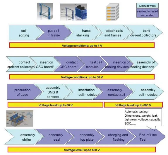
The Mechanical battery pack overview
RESULT:
Thus the battery pack has been designed using ANR26650M1-B cylindrical cells by calculating several cells, battery voltage and capacity. The steps of the battery pack have been explained in detail.