Week 6 - Creating connection for Rear door
AIM:
To set PID for each component and perform the connections for the rear door by using different 1D elements using the ANSA preprocessor tool.
OBJECTIVE:
- The given component is a meshed FE-model. so, there is no need to perform mesh and assigning thickness are not need.
- For the given Rear door FE-model, Create and set PIDs for each different respective components.
- Create the connections like Cluster, Bolt Spot weld, Seam weld, Cbush to be done on the required rear door areas.
- Provide suitable connections for the respective areas and explain for choosing certain type of element for connectins.
PHASES:
At each phase it will explain about the process and a reason for providing each type of connections to specific parts of the given component.
Phase-1
Import FE-model:
- The given FE-model has to be import in ANSA preprocessor tool by File>open select the file should be in .igs or .stp format and then click open.
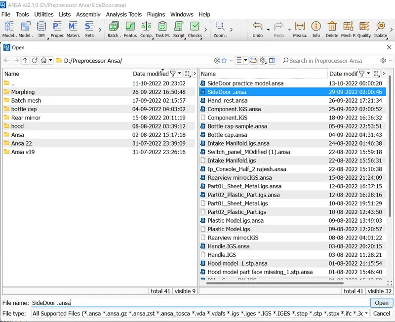
The front and back view of imported FE-model component will be,
- The given FE-model is already a meshed one. so the connections can be perform directly.
Set PID:
- The Property ID has to be assign for each individual seperative parts of the rear door component.
- Assigning PID helps to select unique parts seperately while setting connections in connection manager tool.
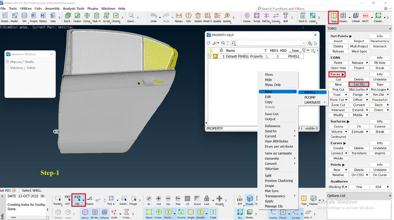
- To set PID select Faces>Set PID in Topo module then select the part and give confirm.
- Then give right click and go to New>Pshell then provide part name and click Ok. Then do double tap on the PID to set PID.
The following images will explain the steps of assignig PID for various parts of the components are,
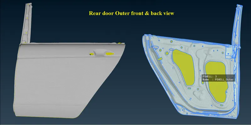
The assigned PID of the various parts are,
CONNECTIONS:
The connections are deployed to make the parts has to be rigid at specific areas to perform stiffness analysis of the material to identify deformation by using simulation analysis.
Types of connections:
There are various kinds of connections that are represented in the FE-model are,
- Cluster
- Bolt connection
- Weld connection
- Spot weld
- Seam weld
- C-Bush connectioin
- Concentrated Mass element connection (CONMi)
All the above mentioned connections are can be carry out through the ANSA Connection manager tool and NVH Nastran deck, a dedicated tool for executing connections.
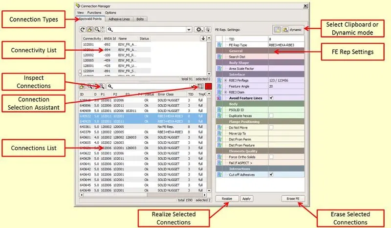
The above image is an Connection manager tool prompt window in that the icons are mentioned in the dialog boxes.
Connection Standard rules in Door:
- For Simulation analysis any vehicle the glass must be in Closed position in the model.
- Any connection in FE-model or in ANSA should not have more than 4 attaching parts.
- At a time more than one bolt connection manager are also possible to perform.
Phase-2:
BOLT Connections:
- The RBE2 is a No Property rigid body element.
- Using RBE2 means no PID defines to particular connections.
- To perform Bolt connection the Two node and many nodes RBE2 are to be used.
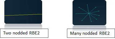
There are two different methods available to represent Bolt connctions are,
- Manual method
- Automatic method
Both type of connection methods are to be endeavor in the Hinges and Hinges supports parts.
Manual method:
- The Manual method are called as cluster type Bolt connection.
- To perform select ELEMENTs>RBE2>Many nodes and select the nodes and give confirm and finish.
- In RBE2 element the rigid spider connection nodes are slave nodes and the center node will be act as master node.
Alternating the Degrees of Freedom(D.O.F.):
- A degree of freedom corresponds to a linear translation and rotation at each axes of the element. There can be up to 6 degrees of freedom per node depending on the element type.
- The attachment between the vehicle bodies and the doors are held by using Hinges. The vehicle doors are clings on the Hinges areas.
- In the Hinges a two node RBE2 has to be deploy between the two master node to constrain the position of arresting the D.O.F of the door.
- But the door has the function of opening and closing for entering and exiting of a vehicle.
- The hinge and hinges supports are used to aid the rotation in Z-direction of the door.
- To perform the rotational movement the 6th D.O.F of rotational Z-axis has to be released or unconstrained.
- So to do that the no. 6 has to be removed in CM-123456 and it will be CM-12345 in the RBE2 pop-up window box. The CM are represented as Degrees Of Freedom.
- The D.O.F has been alternated by releasing the Z- rotational axis which means (XYZ - Linear translation and XY - Rotation has been constrained).
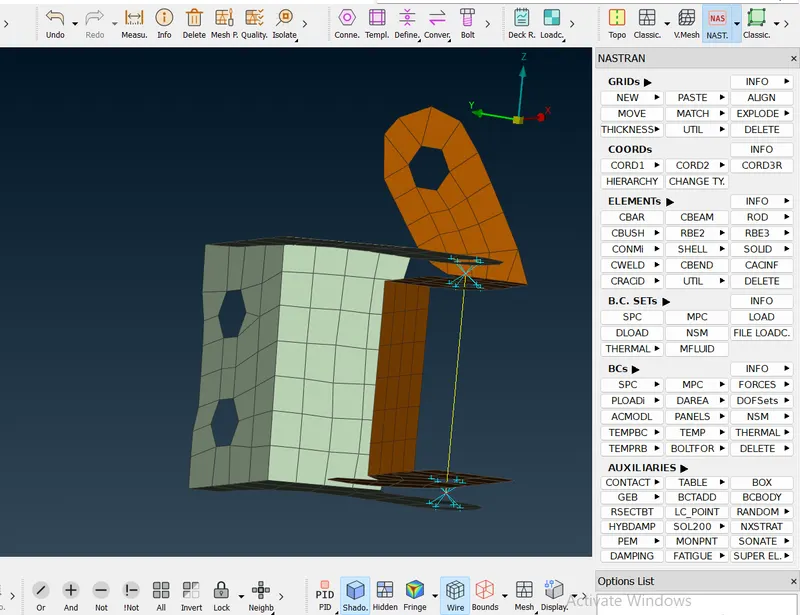
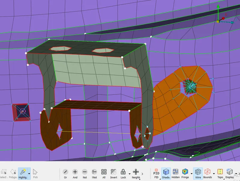
- Those Blue lines are many noded RBE2 and the Yellow line are two node that act as a stem of the Bolt.
Automatic method:
- In automatic method a 3D point has to be created by using Topo module>Points>On COG>Edges at the center point of bolt connection area using the Loop selection tool.
- Then convert the 3D point into Bolt connection type by selecting Convert in Assembly Deck.
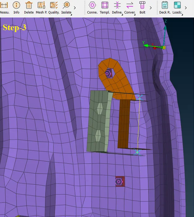
- Now create the RBE2 connection using Connection manager in Assembly Deck and select the Bolt then give confirm.
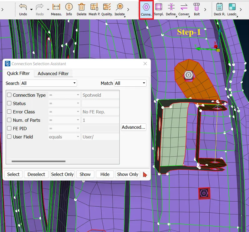
- The Connection manager pop-up window box will be,
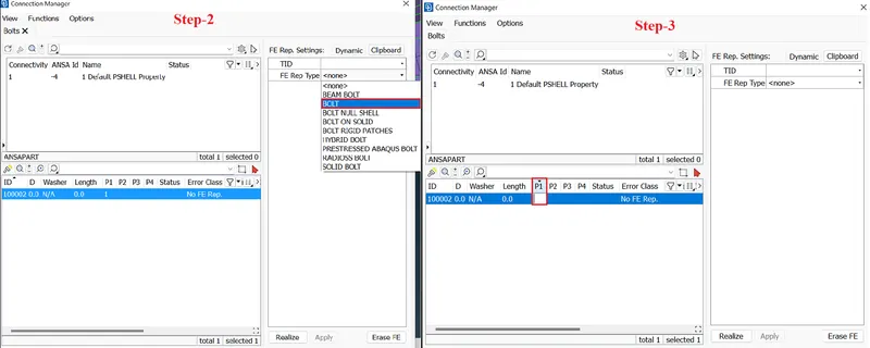
- In the Connection manager window modify the Property ID of Part as P1 & P2 by clicking F1 key.
- In the pop-up Database window do not use the ANSAPART instead always select the Property PSHELL and then select the part and click Ok.
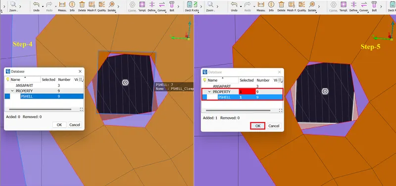
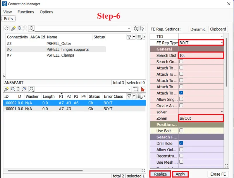
- Now select the FE Represent type as BOLT and give the Search distance by user defined and Zones as In/Out then click Apply and Realize to execute the RBE2 rigid Bolt connection.
The RBE2 rigid Bolt connection will be,
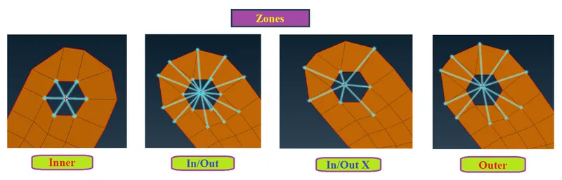
Zones in Bolt connection:
- The Zones are used to set the different kinds od rigidity in Bolt connections.
- The four variant kinds of zones are displayed in the below image are,
Phase-3:
CONMi connection on Door handle:
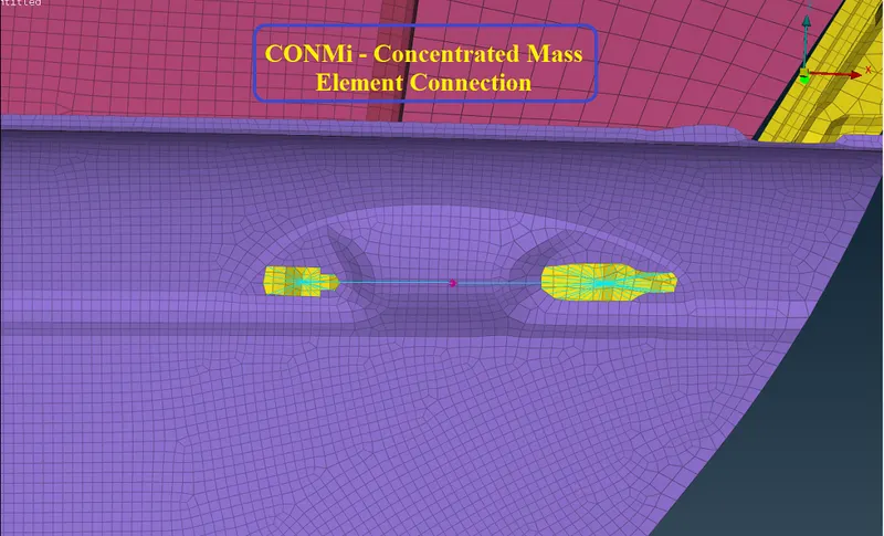
- The definition of CONMi is Concentrated Mass Element Connection.
- Before deploying CONMi connection the many node RBE2 has to be created at the two holes of Door handle area first.
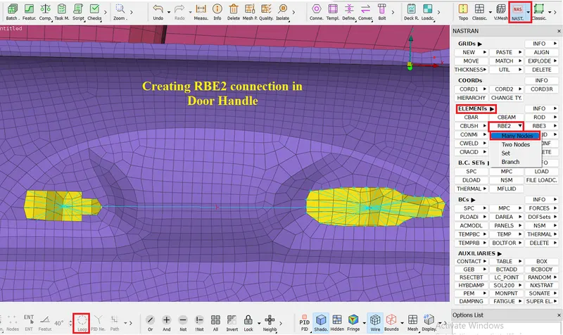
- Now apply the load at the COG of master node created between the door handle joints.
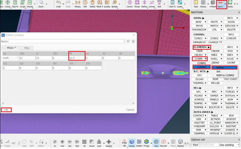
- To perform applying load select ELEMENTs>CONMi>CONM2>Nodes in Nastran module then select the Red Dot and give confirm.
- If considering the mass of the door handle is M=100 gram, it should be converted and entered in terms of Tonnes.
- In the CONM2 window box enter the mass value as M=`1e^-4` and give Ok.
- Now the mass has been assigned which will represent in the Red Dot of master node at COG of the door handle.
Phase-4:
Weld Connections:
- Seam weld connection.
- Spot weld connection.
Seam weld:
- Overlap shell element - To weld parallel sheet metal component.
- Y – joint shell element - To weld perpendicular sheet metal component.
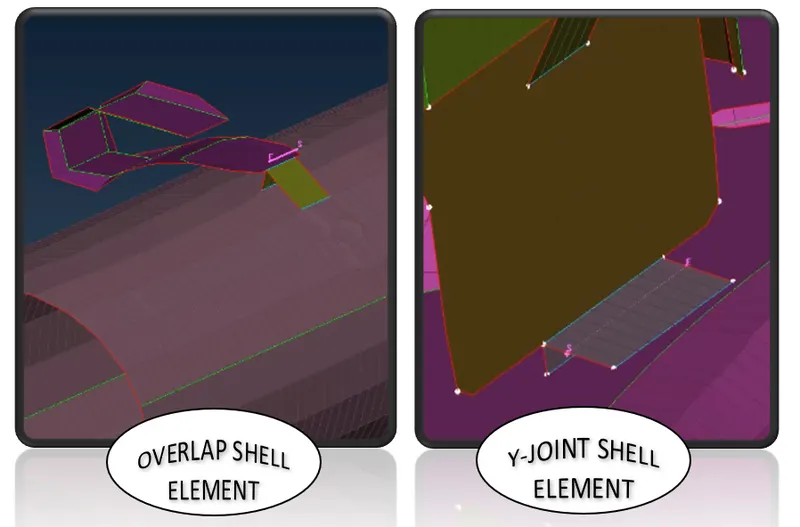
Seam weld connection:
The Seam weld connection are used to weld in the parallel and perpendicular sheet metal areas.
Steps to deploy Overlap shell element connection:
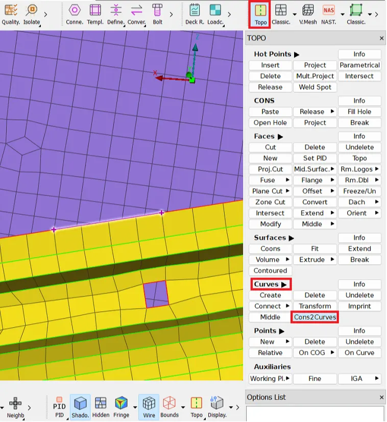
- The Feature line or cons has to be converted into Curve line for creating the Seam weld.
- To create curve line select Curves>Cons2Curvesin Topo module.
- Then select the Cons for Curve line areas at where the Overlap shell connection is required and give confirm.
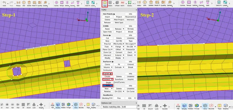
- Then Connect the multi curve into single using Curves>Connect>Multi and select Curves and then confirm.
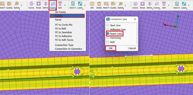
- Now convert the Curve into Seam line connection type by using Convert in Assembly deck.
- Then to create the Overlap shell element Seam weld select Connection manager in Assembly deck and give confirm.
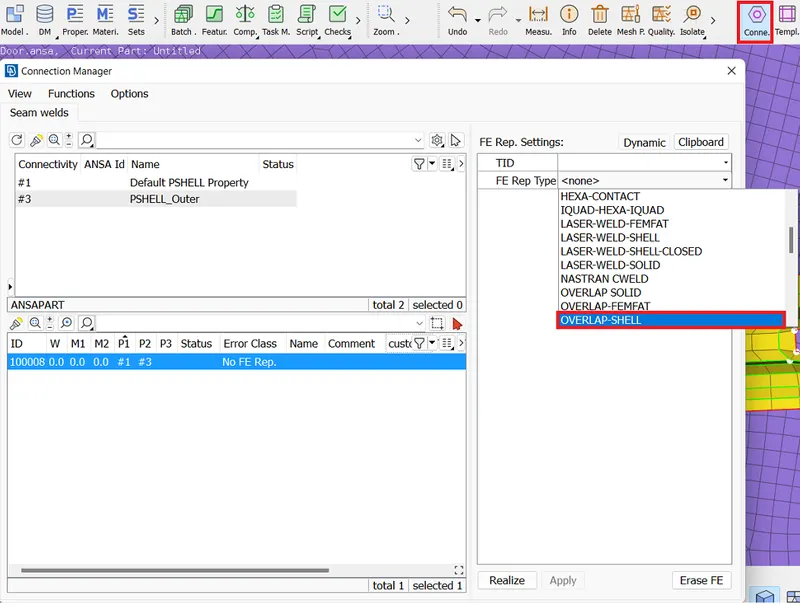
- Now in the pop-uped Connection manager window box provide P1 & P2 are the parts at where the weld joint will be carry out.
- Then select FE Represent type as OVERLAP SHELL and provide the Search distance as user defined value, Base sheet as either P1 or P2 the thickest part to be specified.
- In Weld shape the weld joint Width as to be standard value as 3, step length as 2 as optional, and the root shells as Double row.
- It will became combination of two rows of primary and offset shell elements will be generated between the Feature line to weld root and weld toe.
- Now in Shell Attributes column assign the weld PID by click on Shift + ?.
- In the Property window do Right click and select New>PSHELL>PSHELL to create and on the PID do double tap to assign for weld.
- After entering all the required values for creating OVerlap weld in the Connection manager it will be,
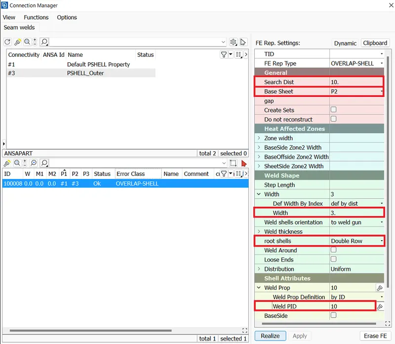
- Now provide Apply and Realize to deploy the Overlap shell element weld and status obtained as Ok represents weld created successfully.
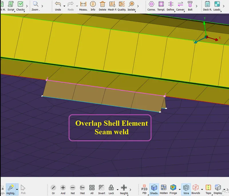
- The thickness of the Overlap weld joint to be T = `frac{t1+t2}{2}`
where,
t1 = Thickness of part P1
t2 = Thickness of part P2
Steps to deploy Y-joint shell element connection:
- Y – joint shell element connection are used to weld in perpendicular areas of sheet metal component.
- If the weld areas have nearby holes or too close to the perimeter the ANSA will not generate the y-joint connection.
- Now to perform seam weld select the FE Represent Type as Y-JOINT SHELL.
- The height and width of the weld must be equal. The height must be provided to the weld.
- Otherwise it will realize from the base of edge of the part and an angle will not be in 45° leads to be a wrong representation.
- The Keep Adjusted shells must be switched ON otherwise the weld portion will deviate the part design to the realizing height.
- In aspect to mesh the deviation is wrong representation. But as per deploying connection at 45° is a correct representation.
- In weld shape the root generation as Project to base will controls the creation of weld root.
- Except these steps all the other steps are same as similar to the Overlap shell element connection.
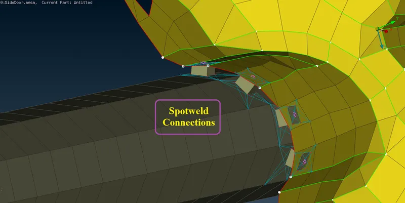
Spot weld:
The spot weld is a solid element connection created between the two parts.
Spot weld can only deploy in the flat surface areas.
- RBE3 Hexa RBE3 element (Solid element)
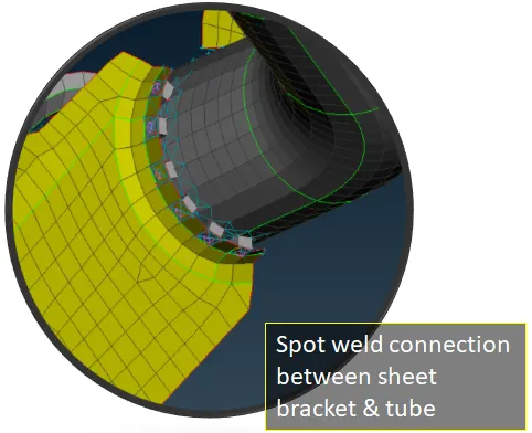
Steps to deploy Spot weld connection:
- The Spot weld are similar to seam weld the only difference is instead of Curve line a 3D points are used.
- To perform Spot weld a 3D point has to created by using Points>On COG>Edges in Topo module and give Ok.
- Now Convert the 3D points into Spotweld point using Convert in the Assembly deck and give Ok.
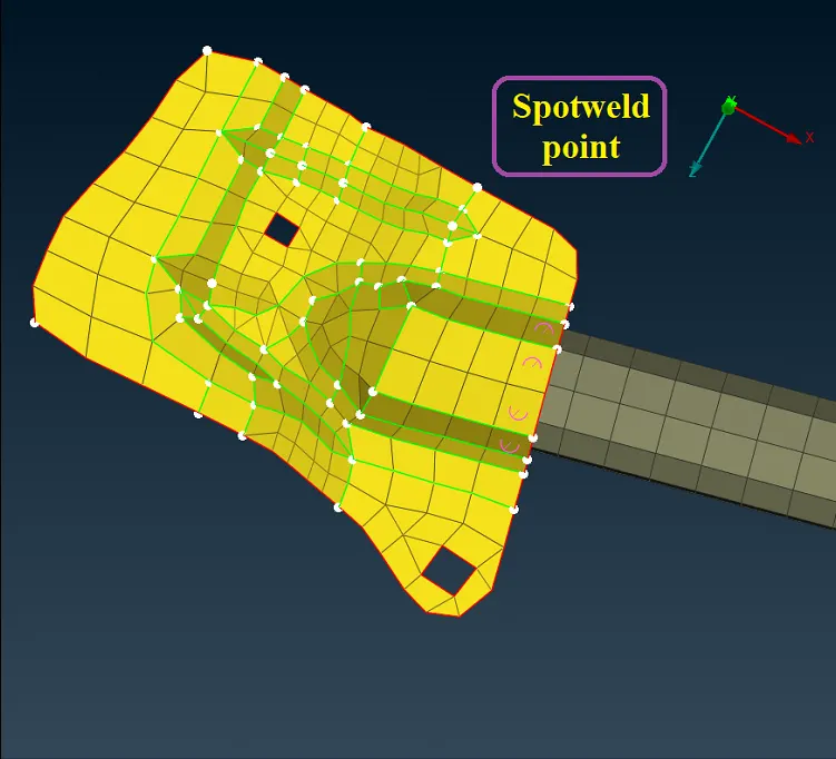
- Now to create the Spot weld select the Connection manager in Assembly deck then select weld point and do confirm.
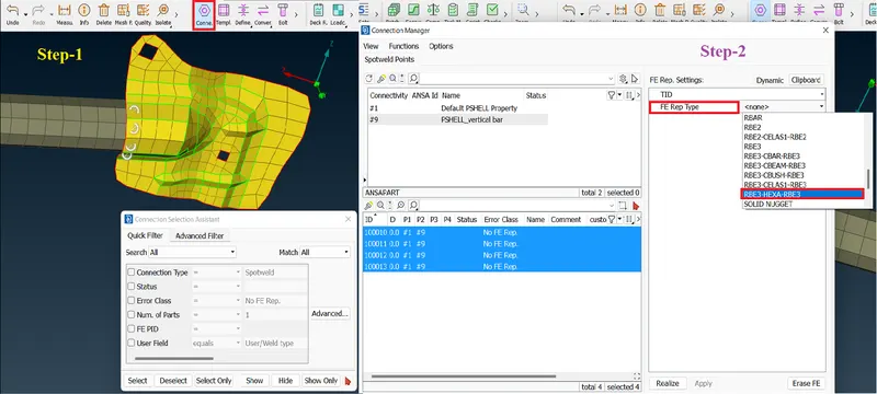
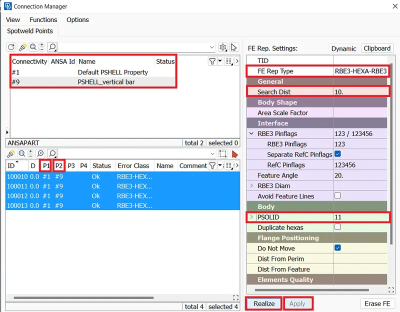
- In the Connection manager window provide P1 & P2 are the parts where Spot weld will be Executed.
- Then to perform Spotweld connection select the FE Represent type as RBE3 HEXA RBE3.
- In that provide Search distance as user defined and in Body content area create new PID by clicking Shift + ? button.
- Now in Property dialog box create new PID and double tap to assign the Prorerty ID.
- Now provide Apply and Realize to execute the Spotweld.
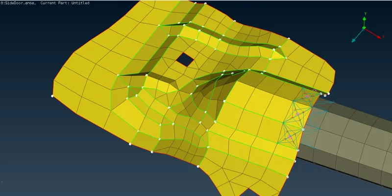
- If the states of the Spotweld is indicated OK means the connection is created successfully.
C-Bush connection:
C-Bush is generally a spring element which will work in a combination of rigidity and damping co-efficient or in other terms stiffness value in three different direction.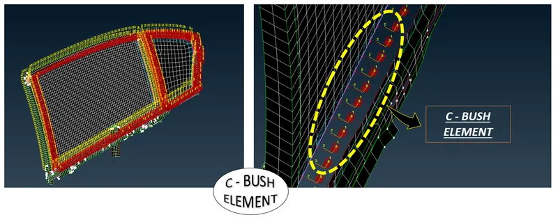
- In door window the Weather strips are placed over the glass periphery will act as a sealent from the outside weather.
- In that area the C-Bush connection has to be deploy. The lower side of the glass are called Window glass line.
- In that line the damping element has to created on either side of the glass.
- On other three sides the damping the connections are made only outer sides of the door glass.
- Because the lower sides the beed supports the mirror push and pulling actions and the other sides are only for mirror guiding.
Steps to deploy C-Bush connections:
- To perform C-Bush connection a damping Spot line has to be created first at the mirror outer line.
- To create Spot line select Perimeters>Feat2Curve in Mesh module and select the mirror outer line and give confirm.
- Then Turn Off the FE-model to visualize the mirror geometry.
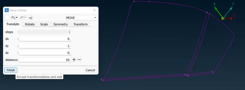
- Now to perform C-Bush on both sides only at lower window glass line copy the lower curve line.
- To create the another lower curve line select Transform>Copy in Utilities deck then select Entities and give confirm.
- Now select Translate dialog box provide the necessary values and click on plus(+) to apply translate on selected direction and give Ok and Finish.
- Now convert the Curve line One by one into Spot line using Convert in Assembly deck.
- Now click on the Connection Manager in Assembly deck and select the Spot line and give confirm.
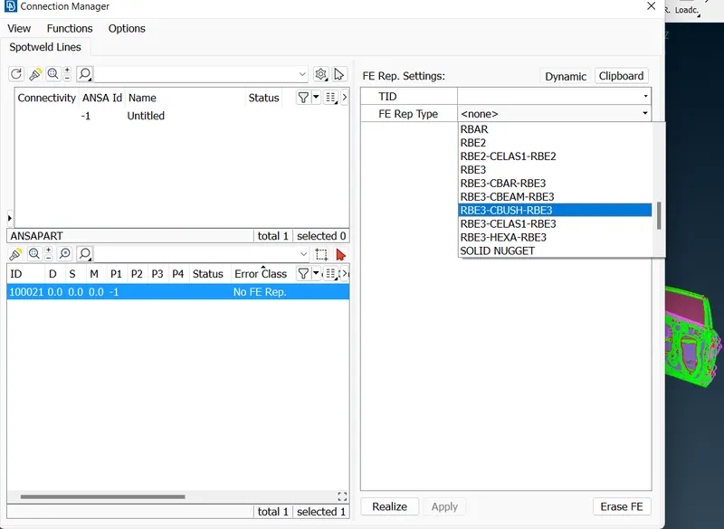
- In Connection Manager window box provide P1 & P2 where the C-Bush will executed by clicking F1 key to select the Property ID. Then provide S value as 10.
- Then to perform C-Bush connection select FE- Representative as RBE3-CBUSH-RBE3 and provide Search distance value as 50 or above as user defined.
- In the Body dialog box provide PBUSH ID by clicking Shift + ? and create PBUSH and give K1, K2 & K3 value as 0.001 and K4, K5 & K6 value as 10 then give OK.
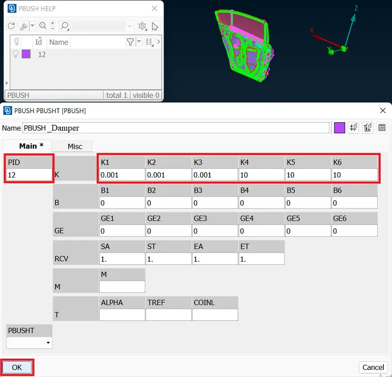
- Now do double tap on the newly created PBUSH to assign the PID then provide Apply & Realize to execute the C-Bush connection.
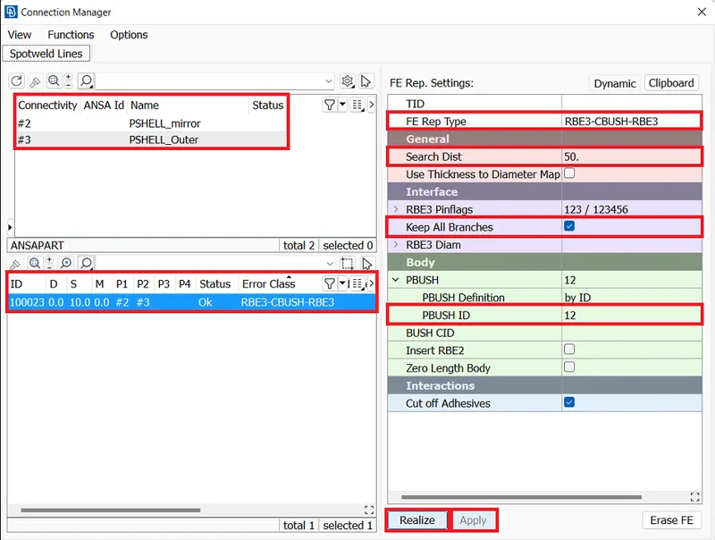
- If the status of RBE3-CBUSH-RBE3 is obtained as OK means that the CBUSH connections are generated successfully.
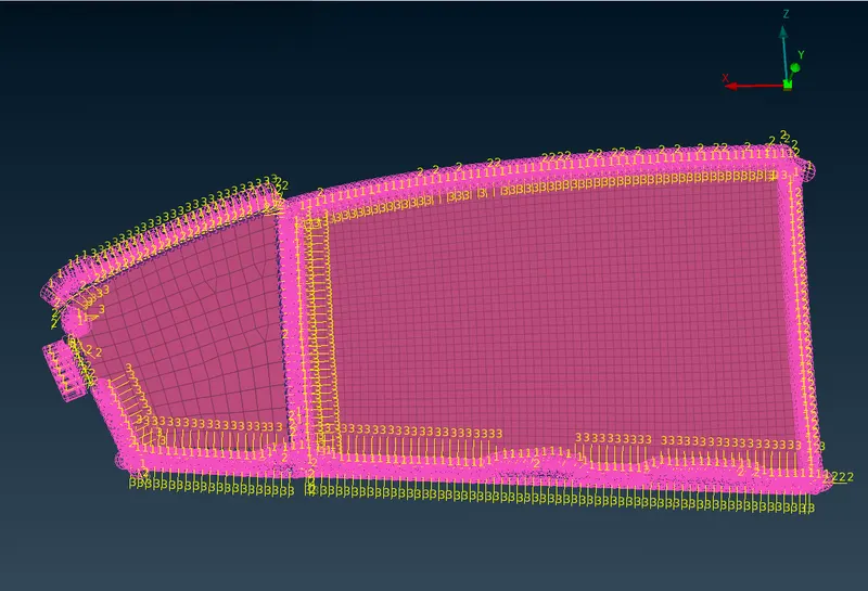
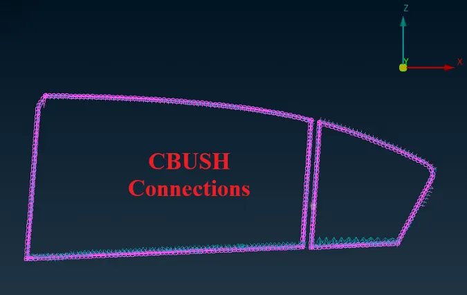
- Now the below image shows that the CBUSH connections appeared around the window area will be,
Rearranging the CBUSH directions:
- The direction of the CBUSH is along the Y-direction on the local coordinates are differ from the Global coordinates.
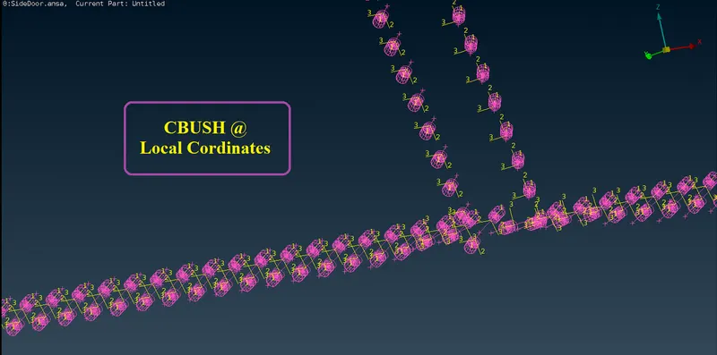
- The Cbush connections are used to find the deflection of mirror at Simulation process.
- The spring values are predetermined and are varying from the products.
- The uneven Orientation of the Cbush connections will affect or tends to a little deviation in the simulation results.
- Due to Search distance and connected parts locations the vector direction will change.
- The direction of Cbush by which it realize are called as vector direction.
- The Direction of Cbush must be arranged to the Global coordinate direction.
Steps to rearrange CBUSH Orientation:
- To perform rearranging Cbush orient open Database as F12 and double tap on CBUSH beloew the Element arrow.
- To change the orient one-by-one in Cbush window box do double tap on Cbush element ID then change the Orient then give Ok.
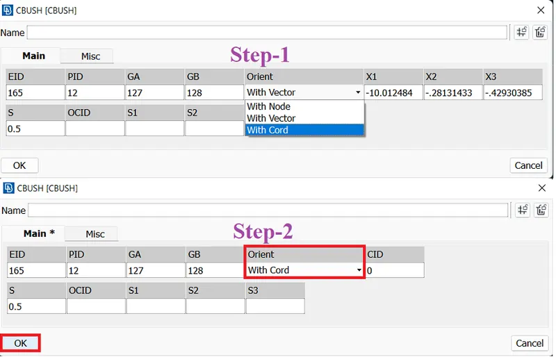
- The GA & GB are the Node numbers and Grid ID's of the bush element.
- Now the direction modified single CBUSH will be,
- To modify all at once open the CBUSH property card select all IDs and do right click and click Modify>New Modification.
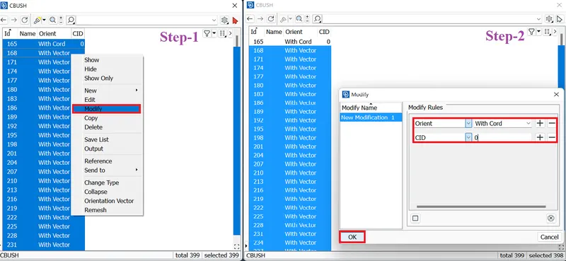
- In Modify results window box enter Orient and select With Coord and enter CID the Coordinate ID value as 0 then give OK.
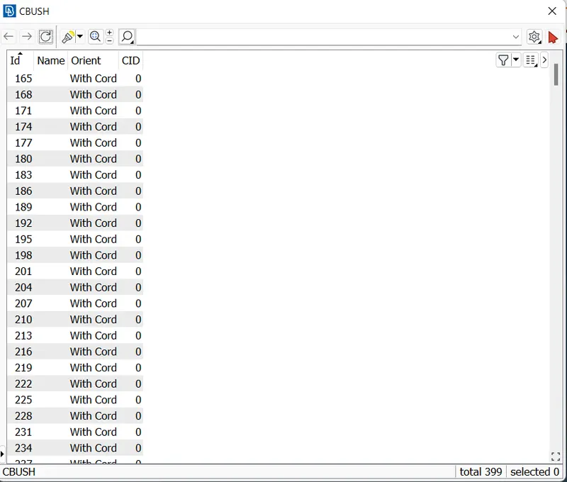
- Providing CID as 0 will also align the elements into Global coordinates.
- Now the modified CBushes are according to the Global coordinates will be,
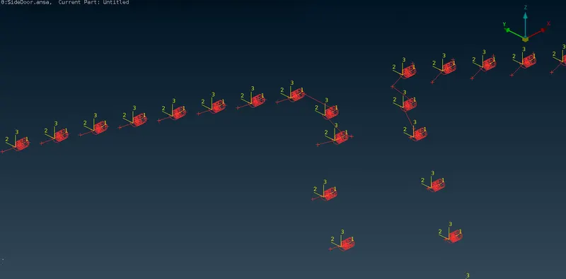
- Even though the vector attachment directions are different, all the CBushes are are aligned to the Global coordinate axis of the vehicle.
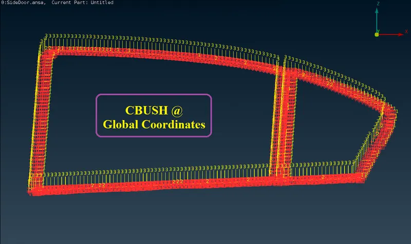
The CBUSH are in Global Coordinate orientation.
Conclusion:
The different types of necessary connections are performed by using Nastran successfully.
Learning Outcomes:
- Understand the deploying methods of various kinds of connections and its applications.
- Explore about the techniques to use the Nastran-NVH module.