Week 3- Geometry cleanup and Mid-surfacing
CASE 1:-
Aim:
To perform mid-surface extraction on the given tube model with proper connections at the tube joint locations using Ansys SpaceClaim tool.
Objective:
To extract the mid-surface and provide connections with sharing options at the tube joint locations for the given tube model.
Procedure:-
- To perform static analysis using "Ansys Workbench simulation software", the Static Structural tool is used. This tool allows defining the model's geometry, material properties, boundary conditions, loading conditions, and other analysis parameters. It includes an Engineering Data tab for specifying material properties.
Importing the CAD Geometry:
- To import the given model to the 3D CAD modeler - "Ansys SpaceClaim", open Ansys Workbench then select Static Structural tool from Analysis systems Toolbox.
- In Static structural tool select Geometry tab--> Import Geometry--> Then select the model to upload.
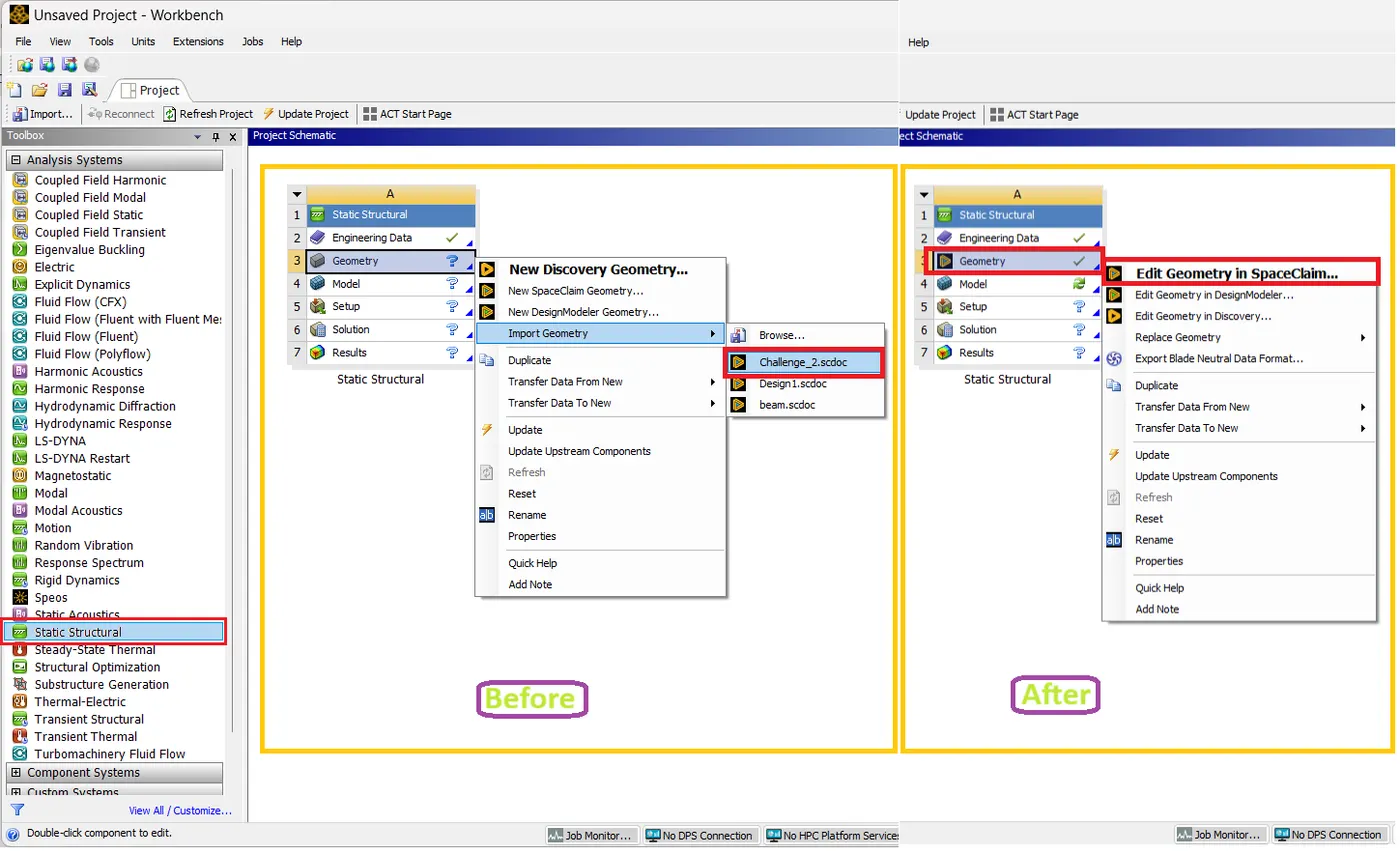
- After Uploading the model go to Geometry tab--> select SpaceClaim to do preprocessing.
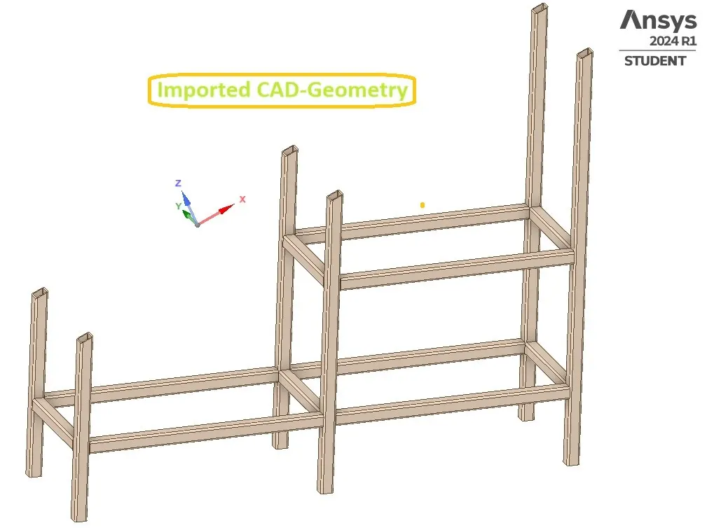
The Tube model in the Graphical window will be,
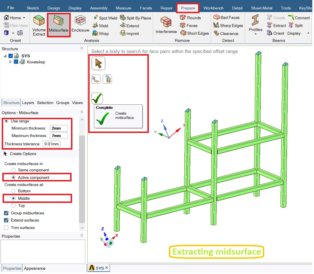
Extracting the midsurface:
- Go to Prepare--> midsurface. In midsurface tab select Use range option and provide max & min thickness range, then select the faces to offset and do complete to extract the midsurfaces.
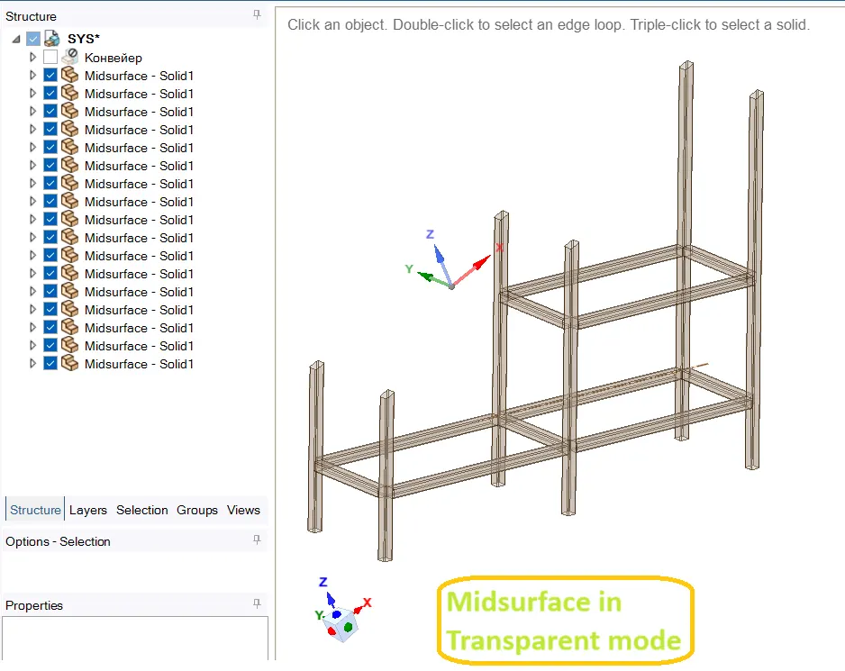
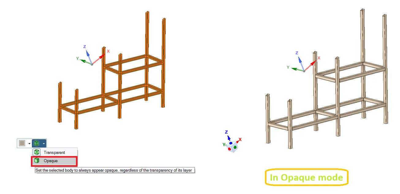
After extracting the midsurface, in transparent mode it will be
After converting the midsurface into Opaque mode will be,
Providing proper Connections:
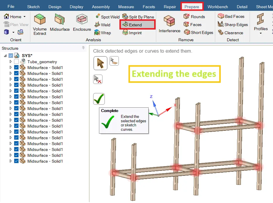
- Before providing the connections, do extending the edges to make the proper connections. To do go to Prepare--> Extend. This tool will automatically found the edges need to be extend, those identified edges can extend automatically by providing complete to extend it.
Use Share tool to do Topology:
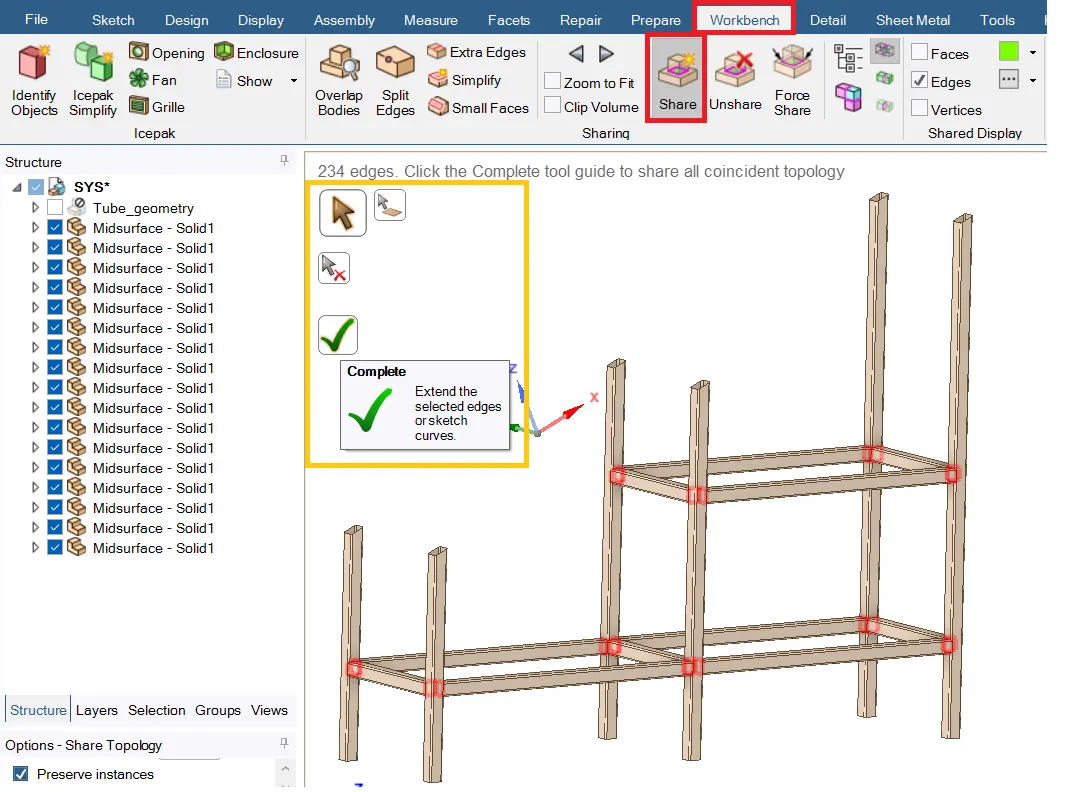
- Now use the Share tool to do Topology by selecting Workbench--> Share and identify the edges then give Complete to do Topology.
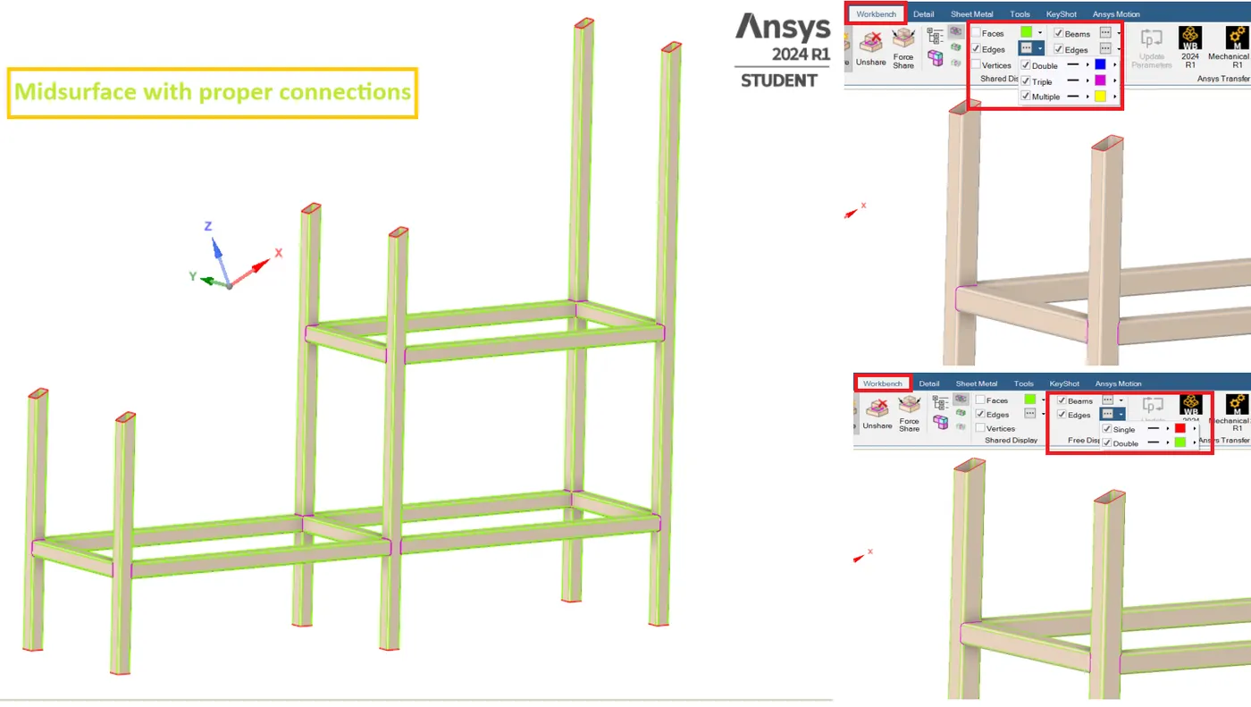
The final midsurface with proper connections will be,
Conclusion:
- The Midsurfaces has been extracted connections are provided with using Share options.
Learning Outcomes:
- Learnt to extract midsurfaces easily with using various options.
- Understand to do extension and to use share option tool to create connections.
CASE 2:-
Aim:
To create a model in SpaceClaim one on top of each other with a shared topology between the top block and the bottom block. Then perform a modal analysis to verify connections and analyze the results.
Objective:
- In SpaceClaim create a model of two blocks one on another with shared Topology.
- By using Ansys Mechanical perform a modal analysis (free-free run) to verify connections and analyze the results.
Modal Analysis:
- “Modal analysis is a fundamental linear dynamic analysis used for linear elastic structures. It is a crucial tool in FEA to understand the dynamic behavior and natural characteristics of linear elastic structures by determining their natural frequencies and mode shapes.”
- These represent the inherent vibration patterns and frequencies at which the structure tends to vibrate freely without any external forces applied (after an initial disturbance).
Modal analysis is also the typical common dynamic analysis for many other dynamic simulations. Such as:
- Response Spectrum Analysis
- Random Vibration Analysis
- Harmonic Analysis
- Transient Dynamic Analysis
The Governing equation of motion behind Modal analysis:
- The governing equation describes the system's movement by considering the forces acting on it and its resulting motion.
- Modal analysis focuses on a system's natural vibrations, achieved by assuming zero external forces and harmonic motion in the governing equation.
Deriving Modal Analysis from the Equation of Motion:
The equation of motion for a structure can be expressed as:
[M] * {ü(t)} + [C] * {u̇(t)} + [K] * {u(t)} = {F(t)}
where:
- M is the mass matrix
- C is the damping matrix (often neglected in modal analysis)
- K is the stiffness matrix
- u(t) is the displacement vector as a function of time (t)
- u̇(t) is the velocity vector
- ü(t) is the acceleration vector
- F(t) is the external force vector (set to zero for modal analysis)
Free vibration:
For free undamped vibration, meaning there are no external forces and damping (F(t) + C= 0). This simplifies the equation to:
[M] * {ü(t)} + [K] * {u(t)} = {0}
Assume every point of the structure experiencing harmonic motion, converts the equation from,
Time Domain --> Frequency Domain
the solution for displacement {u(t)} takes the form of harmonic motion:
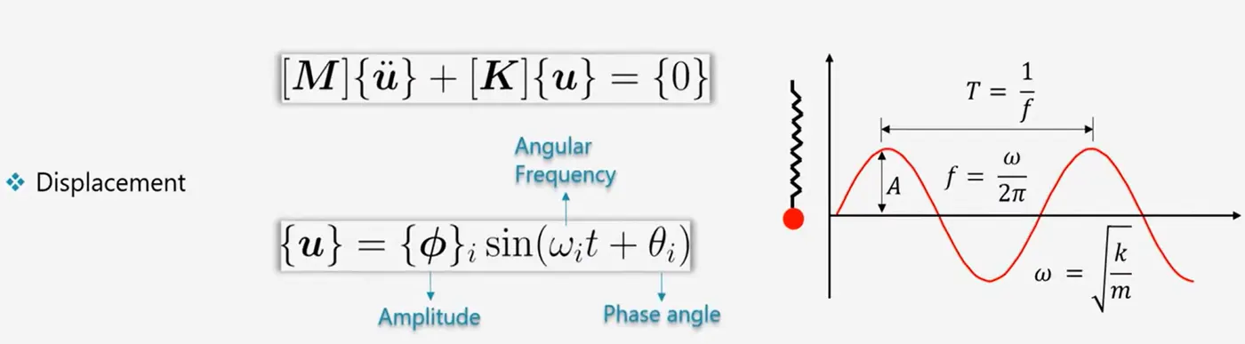
{u(t)} = {φ} * sin(ωt + θ)
Acceleration can be obtained by taking two derivates of displacement with respect to time
{ü(t)} = -ω2{φ} * sin(ωt + θ)
where:
- φ is the modal shape vector (represents the shape of the vibration)
- ω is the natural frequency (radians per second)
- θ is the phase angle (not critical for modal analysis)
Substituting the harmonic expressions of {u(t)} and {ü(t)} to the governing equation will be,
([K] - ω2[M]){φ} = {0}
This leads to an eigenvalue problem where non-trivial solutions exist if and only if:
det ([K] - ω2[M]) = 0
Solving this gives us the natural frequencies (ω) and corresponding mode shapes (φ).
For each natural frequency (ω), solving the eigenvalue problem also gives us the corresponding modal shape vector (φ). This vector represents the deformed shape of the structure at that specific frequency.
- Eigenvalues (ω²) quantify the structure's natural frequencies (squared values). Square root of an eigenvalue gives the frequency in radians per second (rad/s).
- Eigenvectors (φ) represent the modal shapes, depicting the deflected shape of the structure at each natural frequency.
Analogy:
- Eigenvalues: How fast the structure vibrates (frequencies).
- Eigenvectors: How the structure vibrates (shapes).
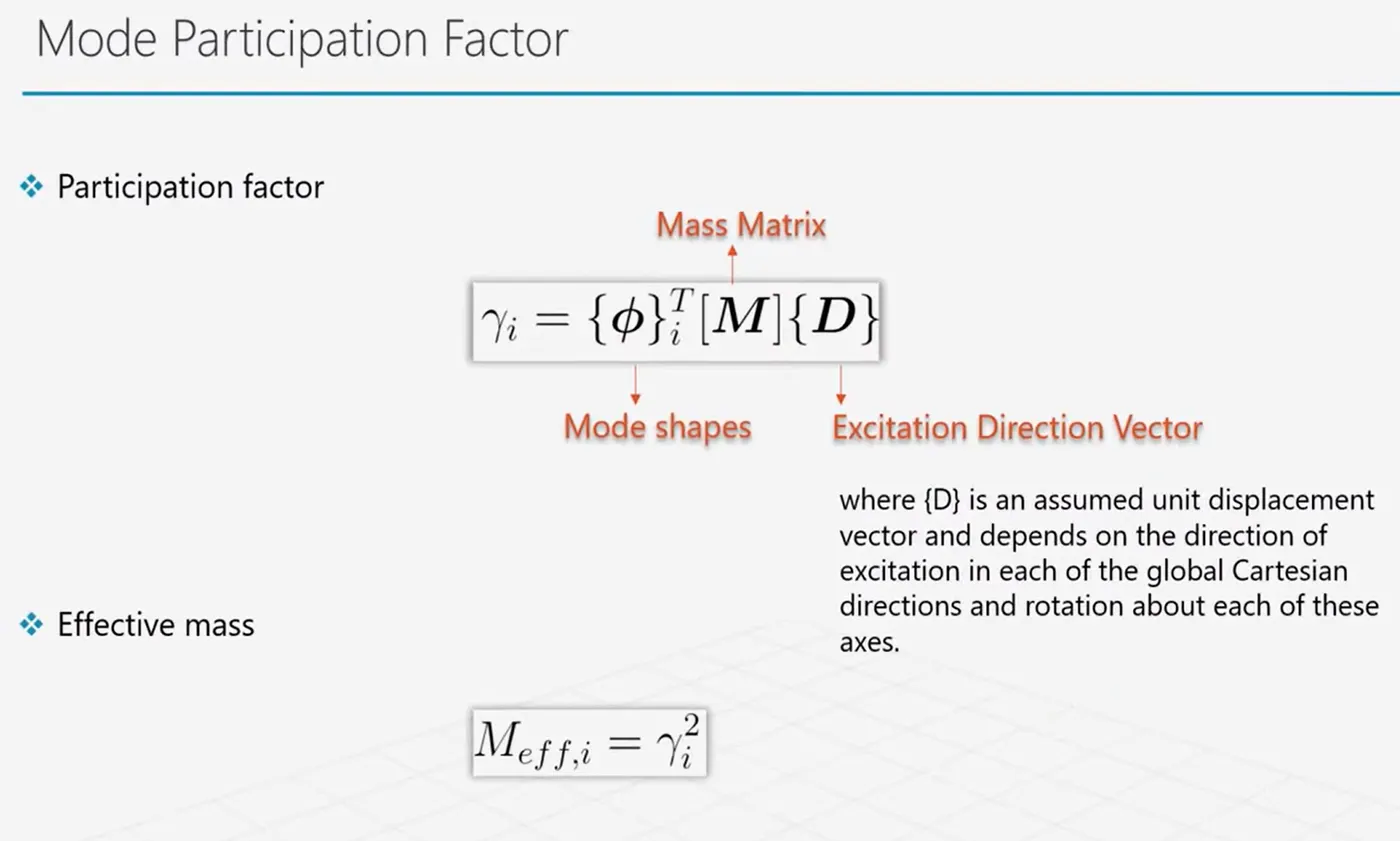
Participation Factor:
A measure of how strongly a given mode contributes to the response of the structure when subjected to force/displacement excitation in a specific direction. Higher MPF indicates a stronger influence.
Effective mass:
The difference between participation factor (PF) and effective mass (EM) in modal analysis:
- Participation Factor (PF): This is a scalar value indicating the relative contribution of a mode to the overall response of the structure in a specific direction. Think of it as a weighting factor.
- A high PF signifies a mode significantly influences the response in that direction.
- A low PF suggests the mode has a minimal impact.
- Effective Mass (EM): This is a value that quantifies the absolute amount of mass participating in a particular mode's vibration in a specific direction. Imagine it as a mass participation meter.
- A high EM indicates a larger portion of the structure's mass vibrates actively in that mode and direction.
- A low EM suggests a smaller portion of the mass participates.
Ratio of Effective mass:
- It shows the percent of overall mass is moving in that direction of specific mode.
Effective mass to Total mass:
- The ratio of effective mass to total mass is used to determine if enough modes have been extracted.
- The material near the support is generally less likely to move. So Effective mass will be smaller than Actual mass based on how much material is located near fixed supports.
- For fixed support Structure the Effective mass < Actual mass.
Modal Analysis Outcome:
The results help predict how a structure will respond to different types of dynamic loading, avoiding resonance and potential failure.
Basic procedure:
The concise procedure to perform modal analysis:
- Do Model setup by creating or importing the Geometry.
- Provide material properties and apply boundary conditions(supports & constraints).
- Generate the Finite element mesh for the model.
- Specify the number of modes to extract (natural frequencies and mode shapes).
- Run the Analysis and view the results.
Select all mode shapes and extract the mode shape results.
- Natural frequencies (eigenvalues).
- Mode shapes (deformation patterns).
- Participation factors (modes excited by forces).
- Effective mass (mass contribution of each mode).
Procedure:
- To create Model and perform modal Analysis using "Ansys Simulation software" the Modal Analysis tool is used.
- It allows to define the geometry, modeling and mechanical analysis and other input parameters.
- It has Engineering data tab that consists of materials and its mechanical properties.
Open SpaceClaim:
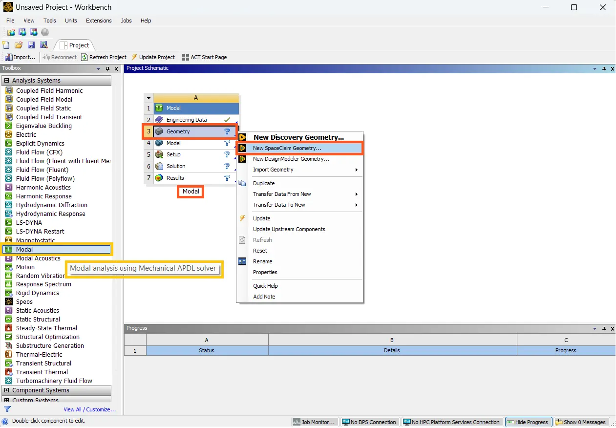
- To create the model in 3D CAD modeler - "Ansys SpaceClaim", open Ansys Workbench then select Modal Analysis tool from Analysis systems Toolbox.
- To open SpaceClaim, in Modal tool select Geometry tab--> New SpaceClaim Geometry.
Dimensions for the Geometry:
Dimension of Top Block A: 20 x 20 x 5 mm
Given data:
- Length: 20 mm
- Height: 20 mm
- Width: 5 mm
Dimension of Bottom Block B: 40 x 40 x 10 mm
Given data:
- Length: 40 mm
- Height: 40 mm
- Width: 10 mm
Drawing the model:
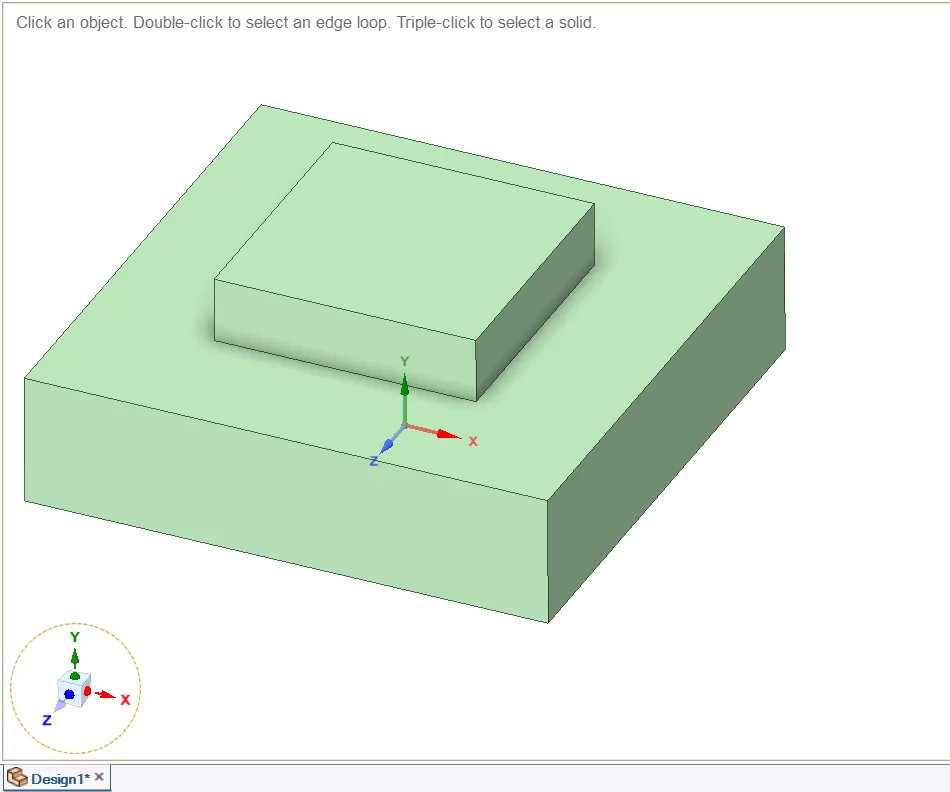
- From the given data, to create the CAD geometry in SpaceClaim use the Sketch tools. Create a rectangle using Rectangle option at specific dimensions. Then use Pull to extend at a given thickness.
- To create another block with shared Topology go to Design--> Sketch mode--> select the sketch plane--> select the Top plane view.
- Now go to Sketch and draw a rectangle and use the Pull option to create a thickness.
Constrain the model setup:
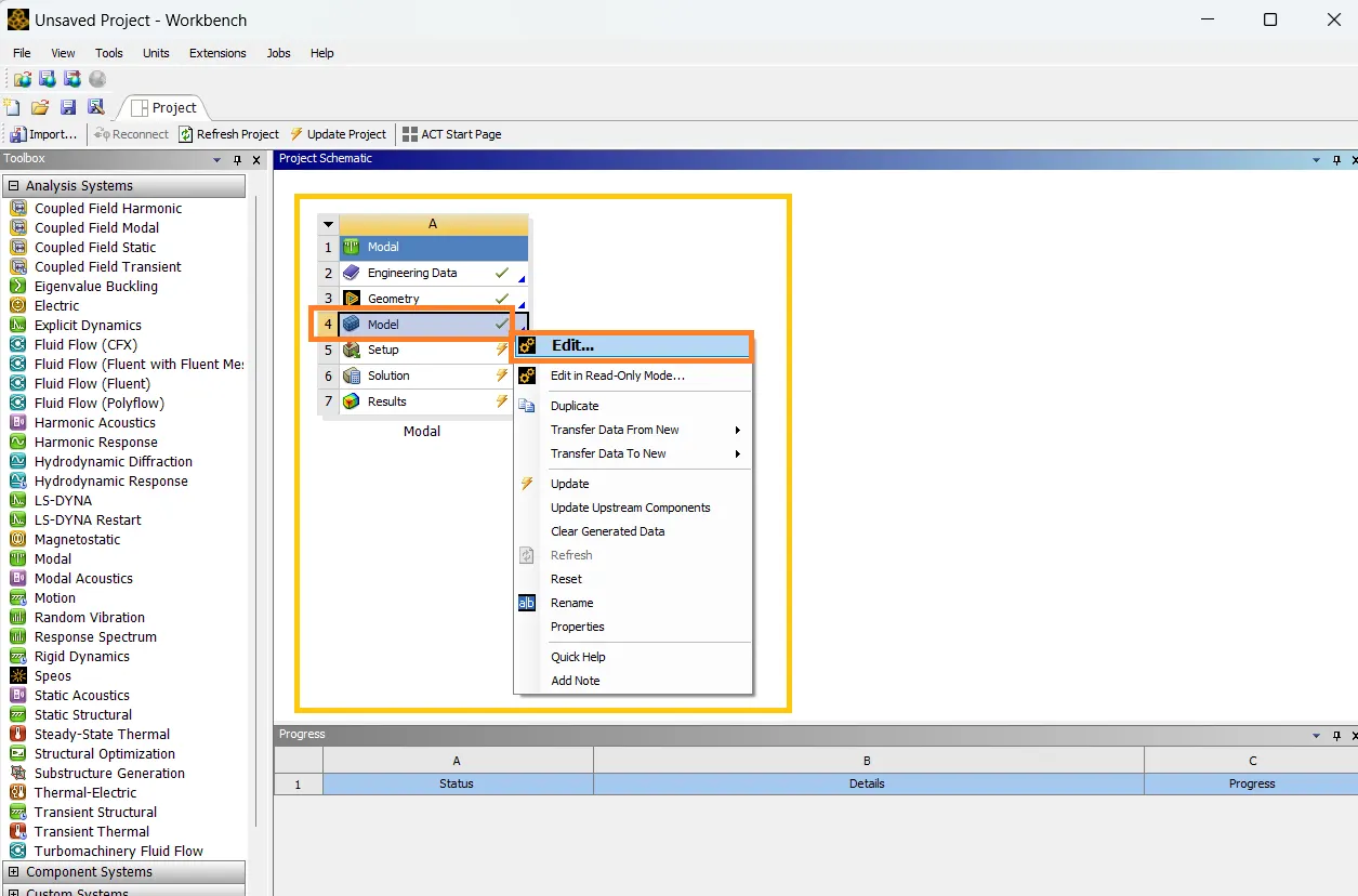
- After creating the model in SpaceClaim go to Ansys Workbench--> Project schematic Modal tool--> Model--> update and select Edit to open Ansys Mechanical to perform modal analysis.
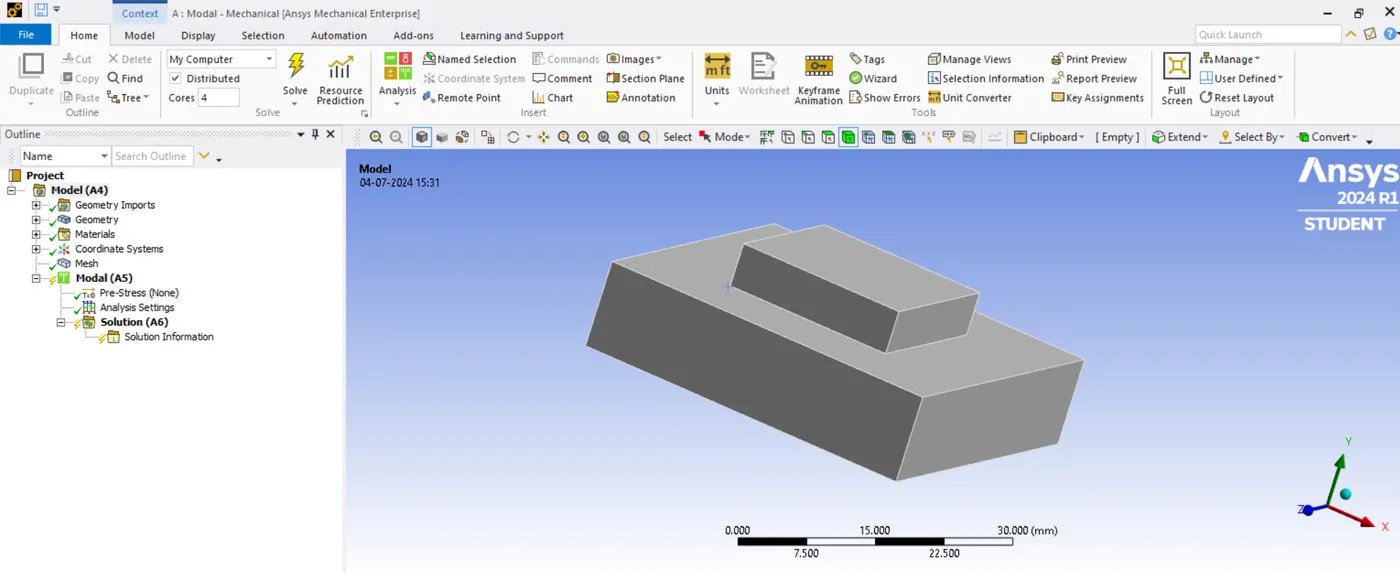
The Updated CAD model in the Ansys Mechanical will be,
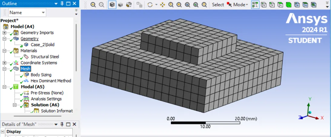
- In Ansys Mechanical go to Outline--> Project--> Mesh--> Insert Sizing & Method.
- Set Geometry and Element size = 2.5 mm in Body sizing.
- Then select geometry and set Hex dominant method with All Quads mesh type in method tab and proceed Generate mesh.
Free-free modal analysis:
It is a specific type of modal analysis used in structural dynamics to determine the natural frequencies and mode shapes of a structure vibrating freely. The following conditions are:
- No external forces: The structure is not subjected to any ongoing loads or forces after the analysis starts.
- Free-free boundary conditions: The structure is not constrained or fixed at any point. Imagine it "floating" in space with complete freedom to vibrate in any direction.
Essentially, it analyzes how the structure would vibrate naturally if left undisturbed.
Desired and undesired modes situation:
- For Free-free modal analysis, obtaining 6-rigid body modes is expected, because the purpose is to calculate the modes when the system is fully or partially unconstrained.
- Besides the free-free modal analysis, there's another situation where engineers may expect rigid-body modes. that is for checking if Grounding exists in a system.
- Grounding refers to a system that has some artificial internal constraints, preventing it from moving freely. It exists due to lack of properly defined or loose connections affects the stiffness matrix of the structure.
- To check grounding, suppress all the constraints (supports and boundary conditions) to run the modal analysis to get rigid body modes.
- In either case, if an rigid body modes have non-zero frequency. Check the contact and correct it.
- If undesired, make sure sufficient boundary conditions or appropriate contact settings are included, so zero frequencies are eliminated.
In Summary:
- Expected rigid-body modes --> Checks Grounding
- unexpected rigid-body modes--> Check constraints
- The free-free modal analysis inherently includes six rigid body modes representing the structure's translational and rotational freedom in space. These modes play a role in verifying the model setup and ensuring the analysis accurately reflects the free-vibrating behavior.
Performing Free-free modal analysis:
- Go to Outline--> Modal--> Analysis settings--> set Max Modes to find as 10 in analysis settings tab.
- Go to Outline--> Modal--> Solution--> Solve to run the analysis.
- After resolved go to Solution results Tabular data and select all modes--> Create mode shape results.
- Go to Outline--> Solution--> Evaluate all Results for all mode frequencies.
- The Natural frequencies for 10 modes of Free-free modal analysis are,
Participation factor summary:
- To get summary result go to Outline--> Solution--> Solution information--> set Solution Output as Participation factor summary.
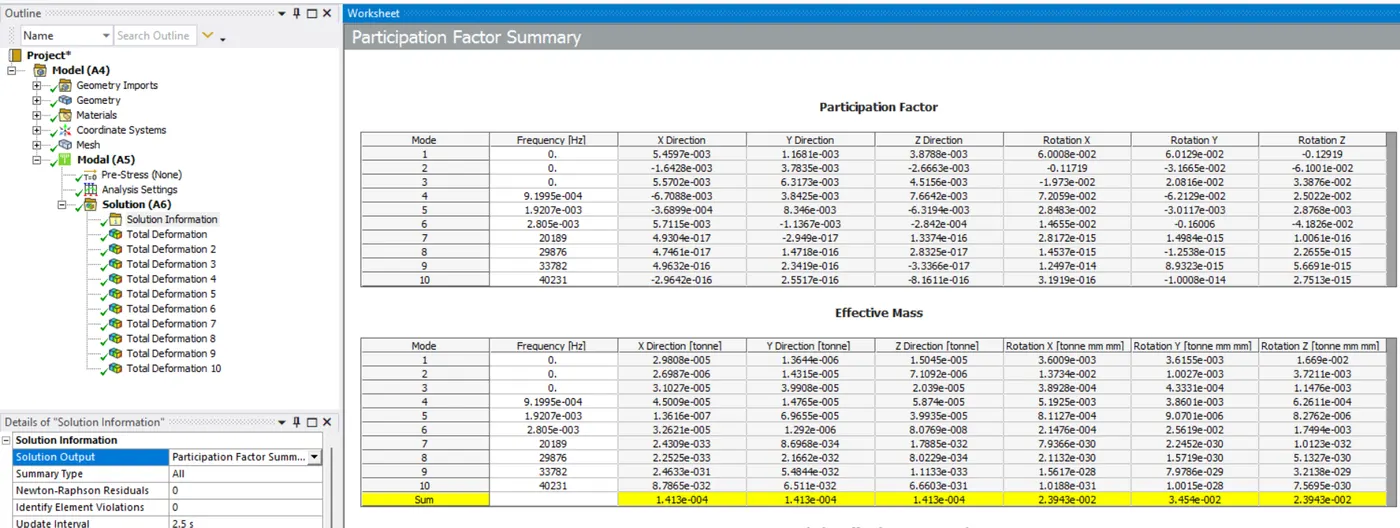
- The participation factor summary for all 10 mode frequencies of the free-free modal analysis:
Result:
- Because to free-free modal analysis, the 1st six modes are zero and near zero frequencies of rigid-body modes.
- After 6th mode all other modes are non-zero frequencies of flexible modes.
- In this case, the highest MPF is (-0.16006) indicating the mode 6 contributes most significantly to vibration in the negative Y-rotation. The structure will be excited by forces in that direction.
- If the excitation frequency in Y-rotation is close to 2.805e-003 HZ, resonance may occur to the structure.
- If Natural frequency of this mode 6 falls within the excitation frequency range, it may undergo resonance.
- The sum of Ratio of Effective mass to Total mass is 1. It denotes enough modes have been extracted.
- The highest Effective mass (ME) is (3.454e-002) indicates the amount of mass participating in a specific mode and direction.
Fixed-base modal analysis:
This is the most common type of modal analysis, where the structure has fixed supports or constraints applied at specific locations. This is the most common scenario to analyze the modal behavior of a structure under realistic conditions.
Performing similar analysis:
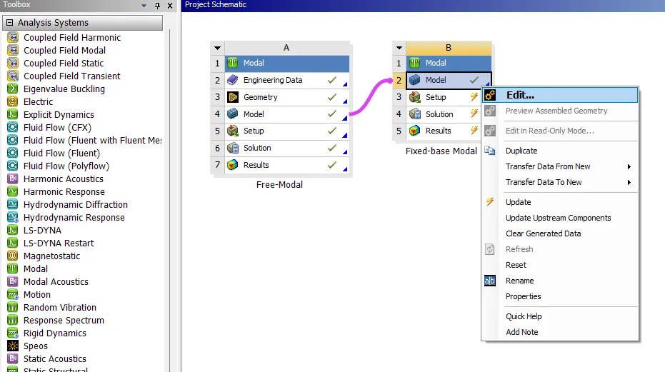
- To perform similar analysis with change in constraints, do sharing between the systems their sections get linked.
- To do sharing, open another modal analysis tool in project schematic window using Ansys Workbench.
- Then section need to shared to be click, drag and put to the other system.
- ANSYS automatically shows the section to which it can be linked by highlighting those sections.
- The result section cannot be shared with any other analysis systems.
Performing Fixed-base modal analysis:
- In Ansys Workbench go to project schematic window, In shared system select Modal--> select Edit to open Ansys Mechanical.
- The model is ready with mesh. Constrain the bottom face of the block by Outline--> Modal--> Fixed Support.
- In Analysis settings, set the Max Modes to find as 10 in analysis settings tab.
- Go to Outline--> Modal--> Solution--> Solve to run the analysis.
- Create mode shape results and evaluate all results of the obtained modes.
- The Natural frequencies for 10 modes of Fixed-base modal analysis are,
Participation factor summary:
- In Solution information tab--> set Solution Output as Participation factor summary to get the summary result.
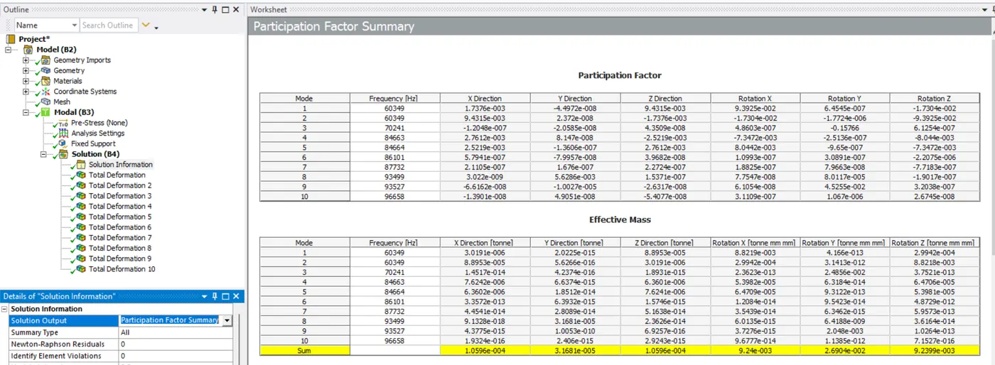
- The participation factor summary for all 10 mode frequencies of the Fixed-base modal analysis:
Result:
- Because to fixed-base modal analysis, all modes are near zero frequencies of flexible modes.
- In this case, the highest MPF is (-0.15766) indicating the mode 3 contributes most significantly to vibration in the negative Y-rotation. The structure will be excited by forces in that direction.
- If the excitation frequency in Y-rotation is close to 70241 HZ, resonance may occur to the structure.
- If Natural frequency of this mode 3 falls within the excitation frequency range, it may undergo resonance.
- The sum of Ratio of Effective mass to Total mass is 1. It denotes enough modes have been extracted.
- The highest Effective mass (ME) is (2.6904e-002) indicates the amount of mass participating in a specific mode and direction.
Comparison:
- By comparing, increase in stiffness of a structure will increases the natural frequency.
- Close to similar value of high MPF with change in stiffness the frequency increases with the same level of mode contribution.
- In rigid body mode the amount of mass participating is higher than the fixed-base mode at increase in stiffness are identified using higher effective mass value.
Learning Outcome:
- Performing Modal analysis are helpful to understand the linear dynamic characteristics of the structure.
- It brings out the method to find the natural frequency and modes shapes of a structure's dynamic behavior.
- It finds the excited modes and amount of mass contribution using the participation factor and effective mass values.
- High MPF value indicates significant mode interaction and high ME value indicates mass contribution in modal analysis.
Performing Modal analysis in FEA helps engineers design better products by:
- Avoiding vibration problems: Identifying natural frequencies to prevent resonance and potential failure.
- Optimizing structure: Using the analysis results to adjust design for desired vibration behavior (e.g., material choice, adding stiffeners).
- Understanding weaknesses: Identifying areas prone to high stress or deformation during vibration.
- Analyzing load interaction: Gaining insights into how the structure interacts with various loads (wind, earthquakes).
This knowledge leads to reduced development costs (fixing problems early) and improved product performance (more reliable and quieter products).