Week- 5 - Solid meshing
AIM:
Solid meshing the given Rear view mirror component after check the geometry errors within the 2D elements quality criterias using ANSA preprocessor software.
OBJECTIVE:
- Mesh the component surfaces with the given 2D element Quality criterias.
- Surface Quality after Volume mesh should be good.
- Only Tet collapse errors to be check and to solve it for volume meshed elements.
- No kinks and raised edges should be present in the meshed component.
2D elements quality criteras
| S.No. | Quality criteria | Value |
| 1. | Target/Average length | 1 |
| 2. | Minimum length | 0.5 |
| 3. | Maximum length | 2 |
3D element quality criterias
| S.No. | Quality criteria | Value |
| 1. | Tet collapse | 0.2 |
PROCEDURE:
The phases used over the given component Cad model to create volume mesh are,
Phase-1 Fixing CAD geometry
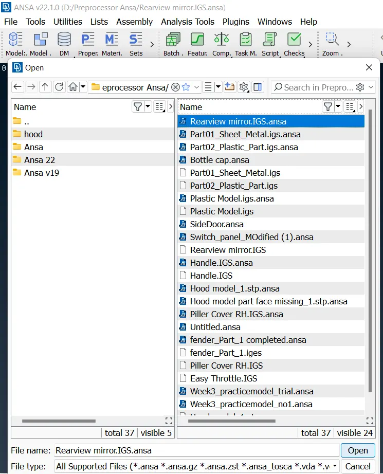
Import CAD:
The given Cad model has to be import in ANSA preprocessor tool by File>open select the file should be in .igs or .stp format
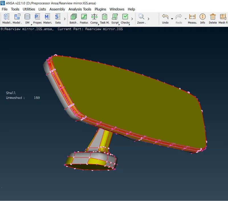
The opened Rearview mirror cad model will be,
Cons resolution:
The cons resolution will improve the resolution of the component are by selecting entire entity on Perimeter>length in clssic mesh deck
Topo Cleanup:
The Topolgy has to be done if the imported geometry doesn't have the surface connectivity. To do Topo in the topo module select Faces>Topo now select the entity to do topo.
Click on Topo and select entity by left mouse window selection and press middle scroll button as confirm.
Phase-2 Geometry cleanup
Checks geometry:
The imported model can have geometry errors like unwanted attached cons or gaps between faces or discrepency.
To solve checks geometry has processed. In the tools deck select Checks>Geometry then click Execute.
The popup errors can resolved by select all and click on fix to auto fix the errors.
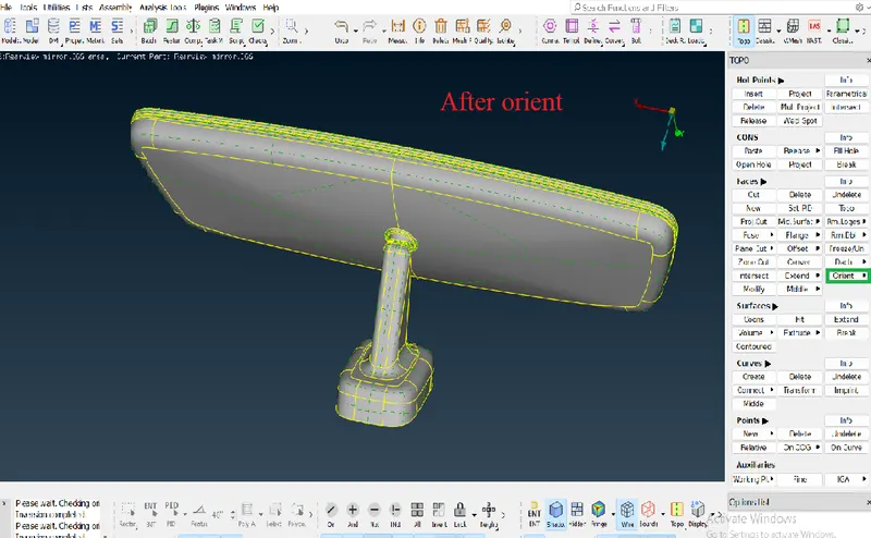
ORIENTATION:
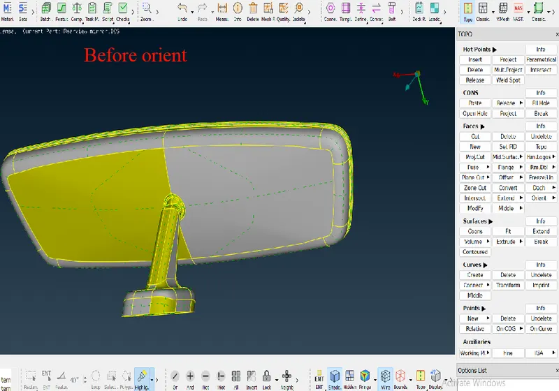
The orientation to be done to make all the faces of surface to be in one normal direction.
MEASURING THICKNESS:
The thickness of the component has to be measured to identify if the model is having uniform or variable thickness.
The thickness can be measured by using weld spot to makes nodes and using multi project to project hot points on opposite faces then using measure to check the distances.
Measure to identify the type of component
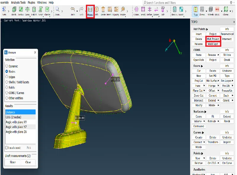
It have variable thickness of more than 6mm describes that the model is a plastic component and there is no need to extract the mid surfaces.
If the model is a plastic component of more than 6mm thickness then volume mesh has to done on the model.
Phase-3 Element quality criteria
MESH PARAMETERS:
In utilities tools click on mesh parameters provide the values for target length and minimum target length as per the given quality criterias.
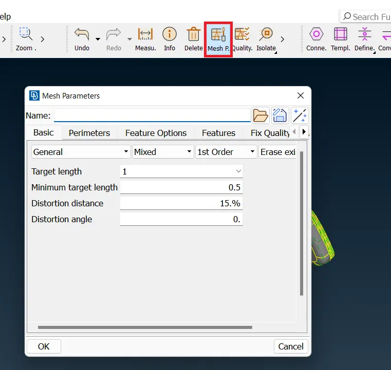
After providing mesh parameters values click ok.
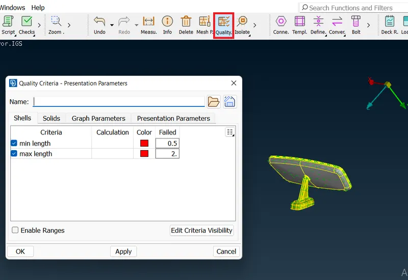
QUALITY CRITERIAS:
Now provide the quality criterias to set the mesh that should come under the spcific criterias.
Select minimum and maximum length in Shells presentation paraameters and set the values.
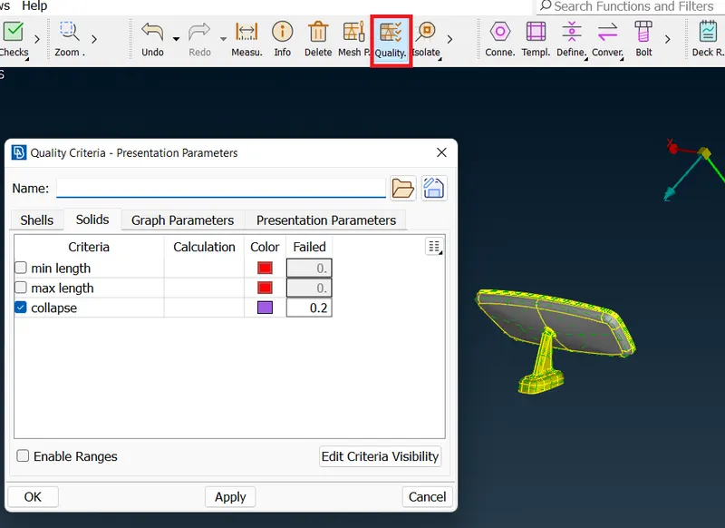
For evaluating the tetra mesh set the values for tet collapse in Solids to obtain solid mesh flow.
Phase-4 Shell/Solid meshing
2D MESHING:
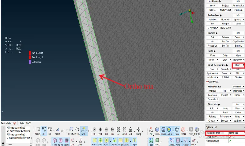
The 2D Tria mesh to be perform in the flat surfaces and Ortho tria mesh to be performed in the curved surfaces.
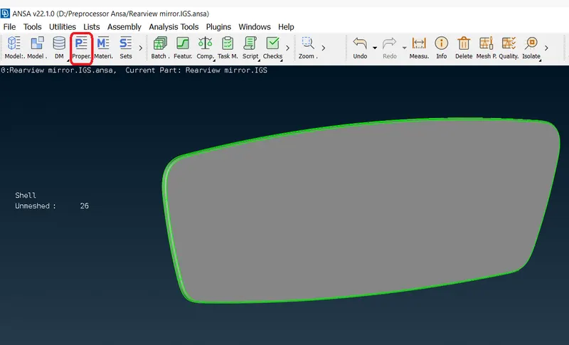
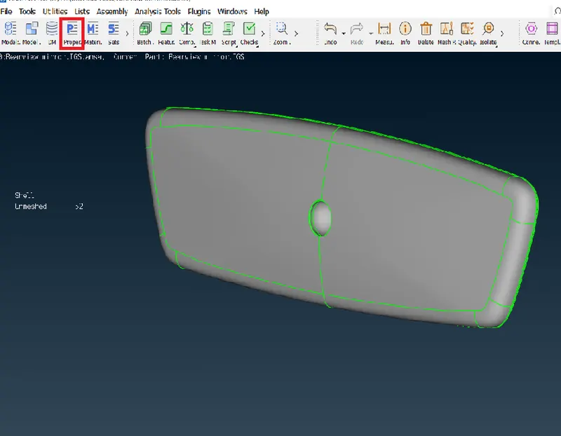
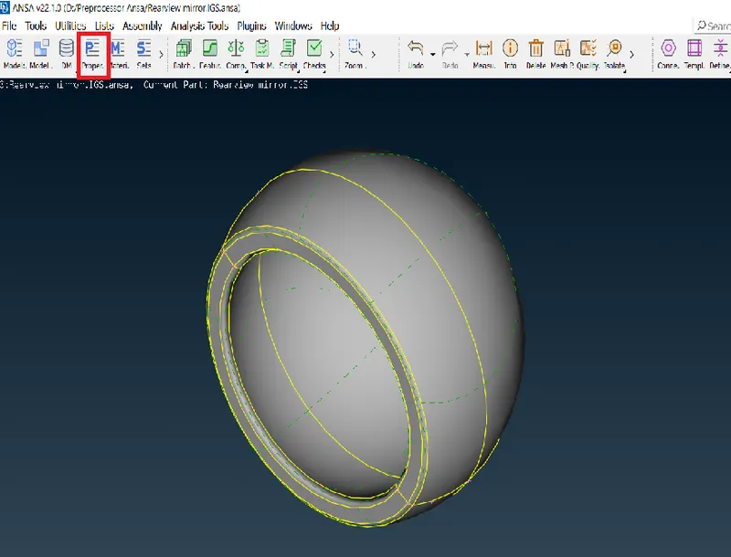
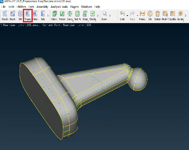
The 2D mesh to be perform int he given component by splitting up the component into four various parts having diferent properties that are shown below:
CAPTURING FEATURE LINES:
There will be some feature lines that will fail the mesh elements in the component.
Those defeaturing lines are to be supressed to avoid the elemental failures of preferred quality criterias.
SUPRESSING DEFEATURE LINES:
In rearview mirror back case the feature line are below the minimum target length quality criteria .
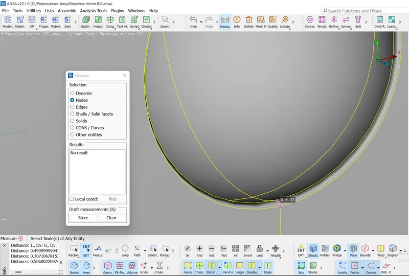
To capture this fillet area any feature line as to be supressed.
Supressing the line by joining the lines using Faces>Join in Topo module.
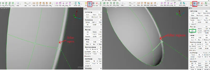
Defeaturing lines in inner sphere component
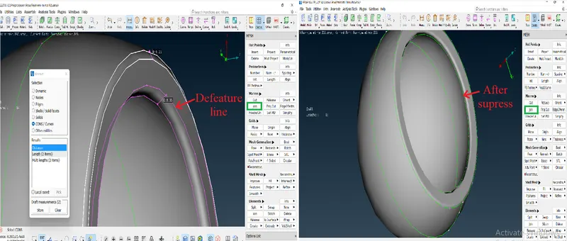
THe defature fillet lit lines are supressed using Join command.
Now check any defeature lines are present in the rearview mirror handle to be supressed using Join command.
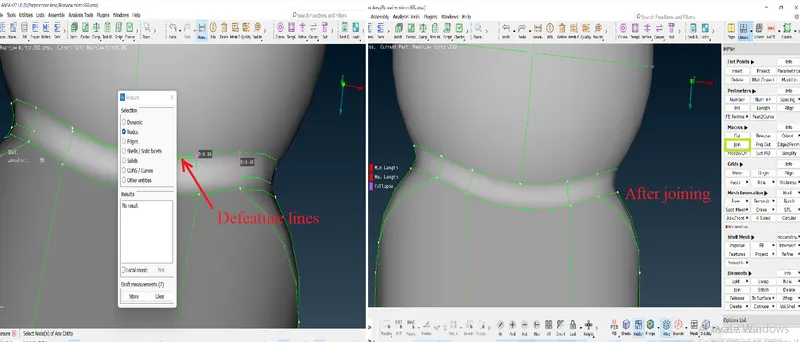
Now in entire component the defeature lines are get supressed.
MESH SIGNIFICANCE:
- By meshing the component it influences the accuracy and speed of simulations.
- In this process, the continuous geometic space of an object is broken down into thousands and more of elements to properly define the physical shape of the object.
SHELL MESH:
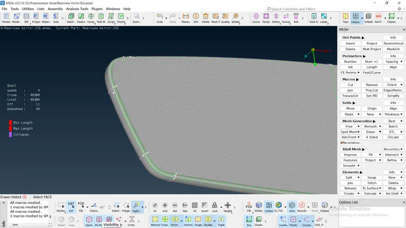
- The flat surfaces of the component are to be meshed with 2D Trias
- The curved surfaces are to be meshed with Ortho trias.
- To do mesh on the CAD geometry the Tria mesh has to be used.
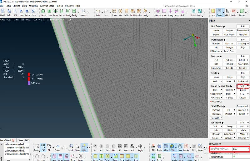
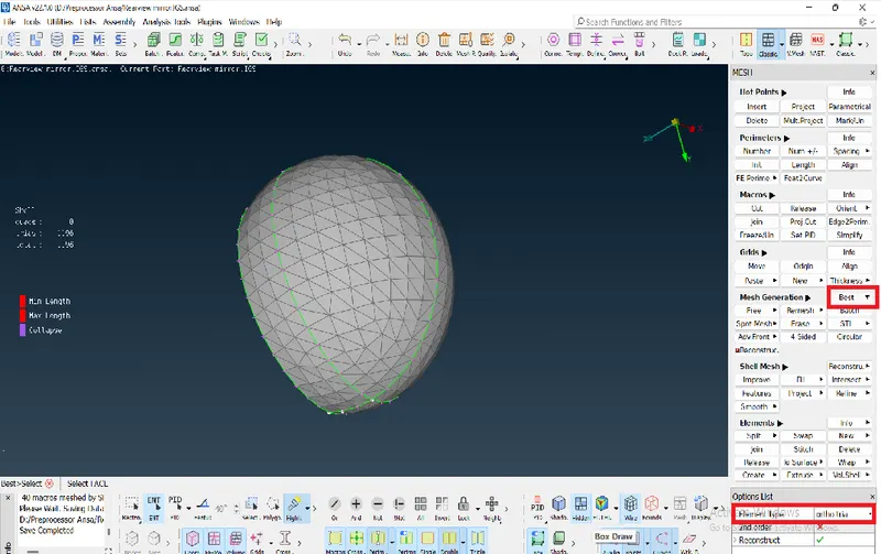
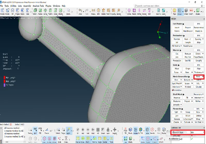
- The Tria mesh to be selected by selecting Mesh Generation>Mesh and in option list select element type : Tria and select flat faces and give confirm by clicking on mouse scroll button.
Part: mirror
Mesh element type: Tria
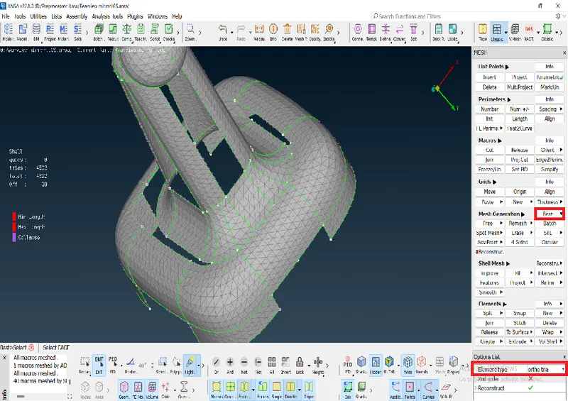
The Ortho tria element type has to be used for solid meshing the curved surfaces.
Mesh element type: Ortho tria
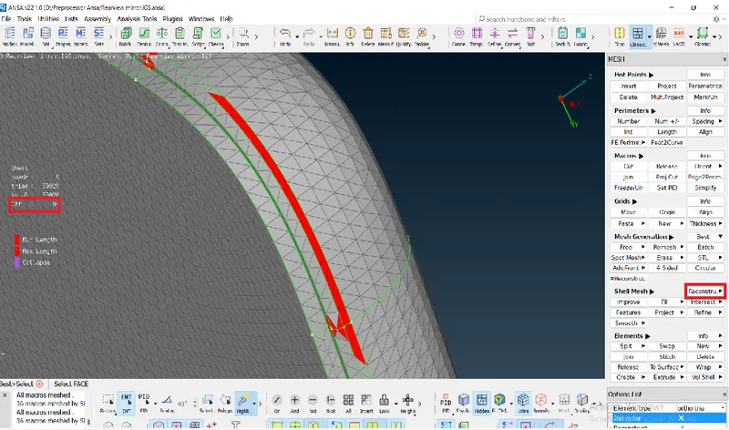
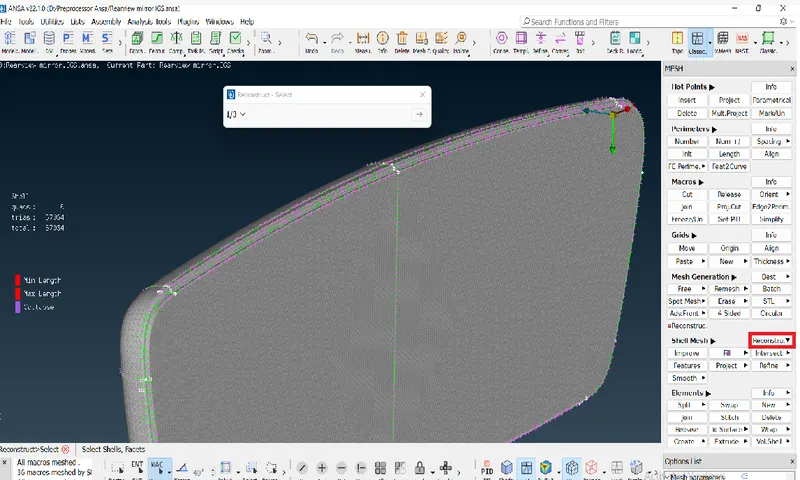
Part: Rearview mirror back case
Mesh element type: Tria
Mesh element type: Ortho tria
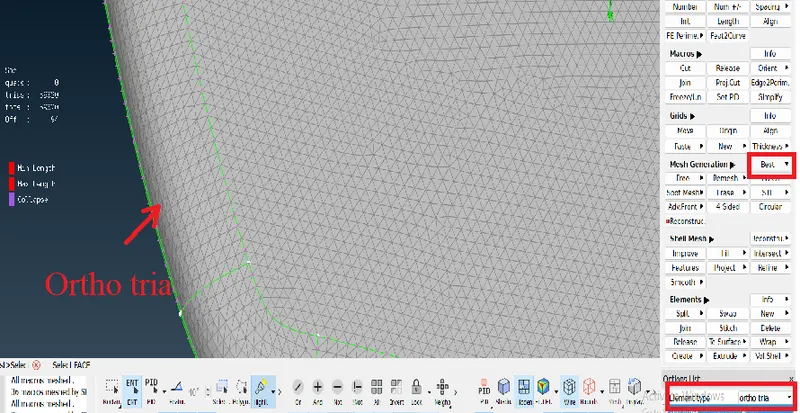
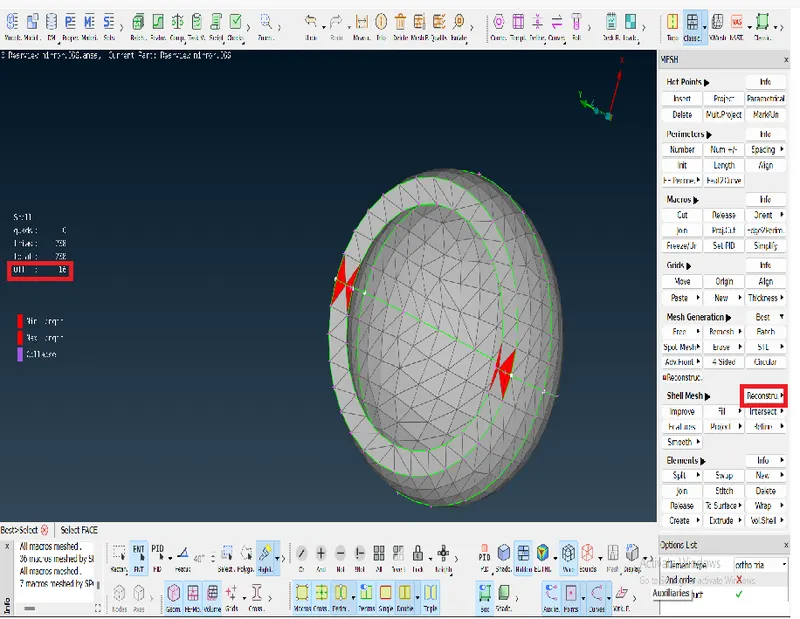
Part: Inner sphere
Mesh element type: Ortho tria
Part: Rearview mirror handle
Mesh element type: Tria
Mesh element type: Ortho tria
By selecting show only on unmeshed To select the unmeshed faces easily.
Phase-5 Mesh improvement
BETTER MESH FLOW:
The meshed faces will have elemental failures in quality criterias.
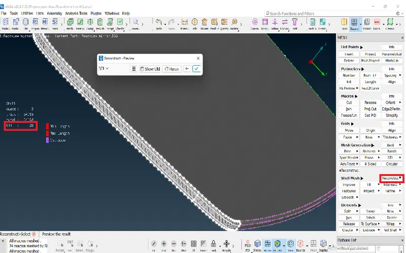
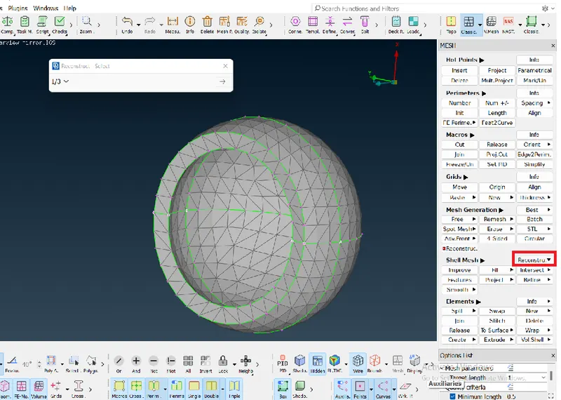
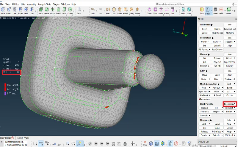
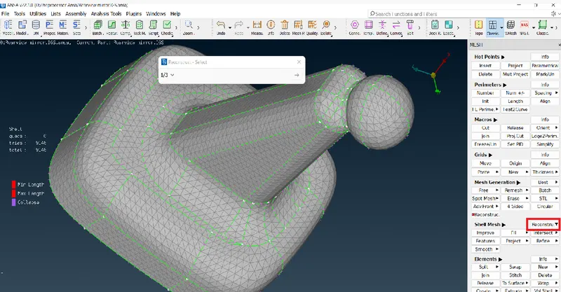
It should be resolved by using Reconstruction and Smooth tools in Shell mesh.
Part: Mirror
The OFF elements are resolved using Reconstruction
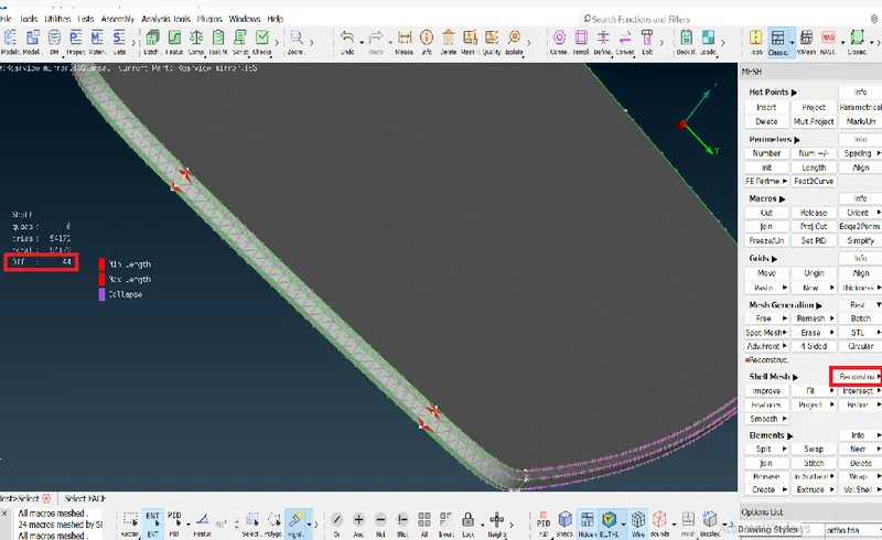
After Reconstruction
Part: Rearview mirror back case
Before Reconstruct
After Reconstruction
Part: Inner sphere
Before improvement
After improvement
Part: Rearview mirror handle
Before improvement
After improvement
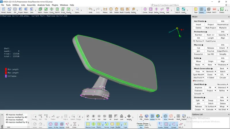
FINAL MESHED CAD GEOMETRY:
Phase-6 volume mesh:
VOLUME DEFINITION:
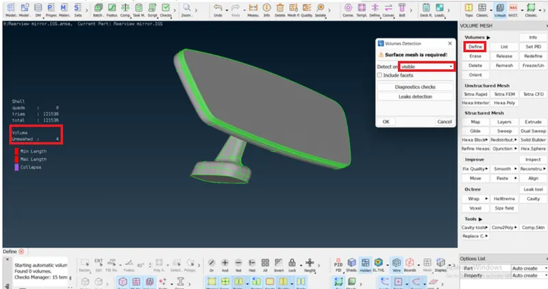
To provide the volume definition click on Volumes>Define in V.Mesh and select visible in Detect on.
TETRA RAPID:
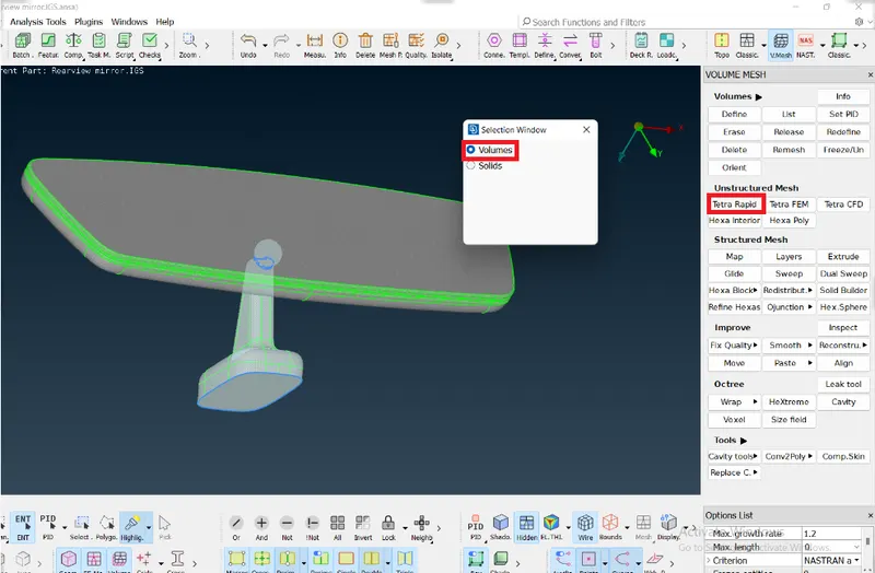
Now to convert the Shell mesh to Volume mesh select Tetra Rapid in Unstructured Mesh. Now click on volumes and select the entire component by window box selection and give confirm.
PSOLID PROPERTY:
Now the Psolid property for volume mesh has generated.
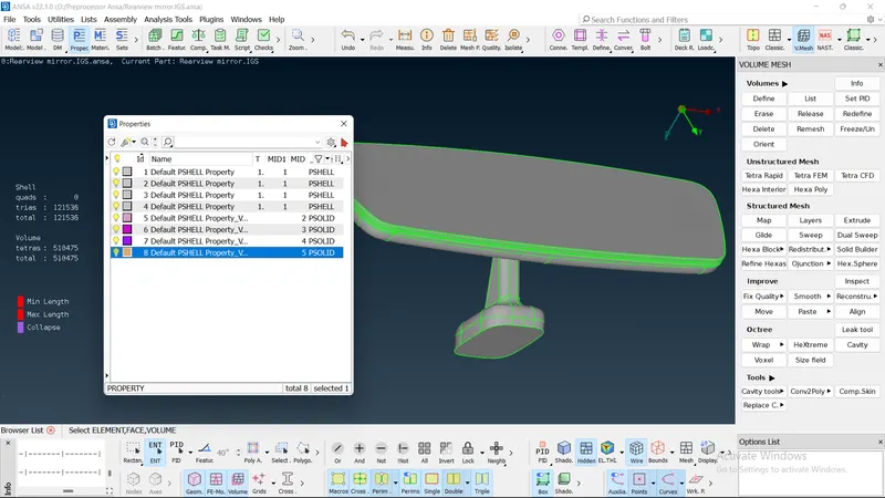
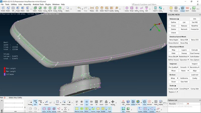
PSOLID MESH:
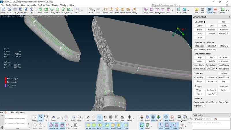
VOLUME MESH SURFACE QUALITY:
The surface quality of the volume mesh is achieved with zero OFF elements.
LEARNING OUTCOMES:
- Learned the Volume mesh on meshing the Cad geometry using Tria elements and Ortho tria elements.
- Learned to define the volume and apply Tetra rapid for volume meshing.
- Learned to clear the errors such as kink, dip and tet collapse elements.
CONCLUSION:
Therefore a given Rearview mirror model geometry errors are checked and 2D shell meshing over the surfaces are provided.
The volume mesh is defined and the Tetra rapid are used to create the solid mesh.
The volume mesh is created with good quality in the sufaces with zero OFF elements.