Week 4-1D Element Creation Challenge
1D ELEMENT CREATION CHALLENGE
AIM:
To create the Mesh and 1D Element connection on the given component using the Hyperworks Pre-processor tool.
OBJECTIVE:
Generate Mesh on the given model with the Target element size of 5 Units.
Create 1D element on the given component with the provided cross section and DOF, then assign property to them.
PROCEDURE:
Import CAD model:
The given CAD model is in .IGS format.
To open the model select Import file--> Import Geometry--> File selection window--> File type as IGES--> Select file--> Import.
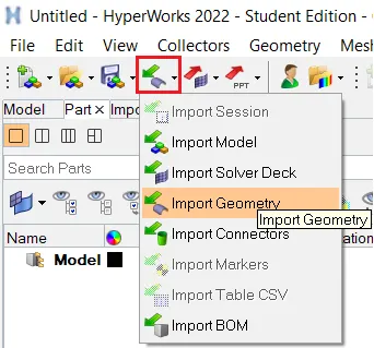
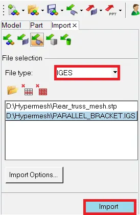
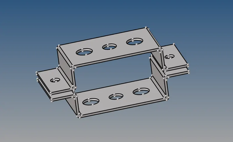
The imported CAD model in the Graphical window will be,
Deleting the solid component:
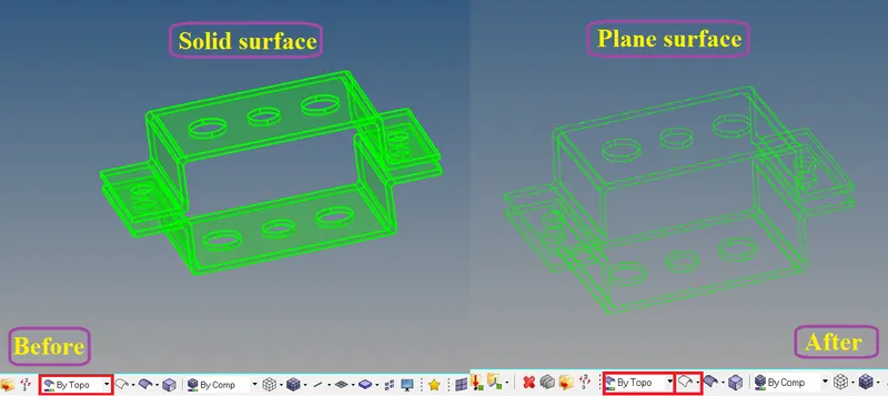
Before creating midsurface the solid surface has to be removed from the component. To do that select Delete--> solids--> all --> delete entity to remove the solid from the component.
Extracting the midsurfaces:
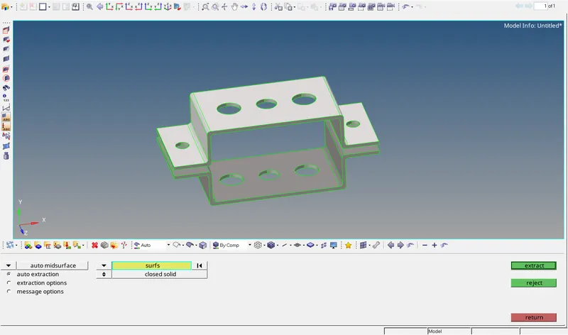
To extract the midsurface select main menu--> Geom--> midsurface--> auto midsurface--> auto extraction-->surfs--> extract.
The extracted midsurface with the component will be,
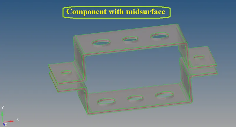
Now delete the parent geometry components which are all not required.
Then create the component ID for each midsurfaces by selecting model tab--> right click--> create--> component.
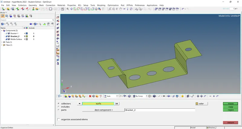
Then Organize the midsurface seperately to each created component ID by selecting main menu--> Tool--> organize--> surfs and select specific midsurface and set the dest component as created component ID and click move.
The final midsurfaces with the associated component ID will be,
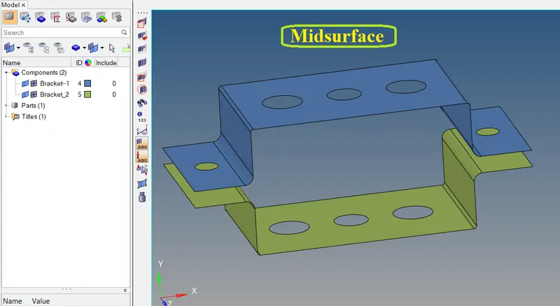
Reason for creating midsurface:
- The midsurfaces are the conversion of 2D and 3D CAD component. The midsurfaces are meshed by Shell elements.
- The Shell elements are the 2D representation of 3D elements of hexa and Tetra.
- Meshing on midsurface reduces the no. of nodes and elements and required less storage space to store the preprocessed component.
- The preparing midsurfaces will reduce complexity by simplifying the CAD model to get precise simulation results in less time.
Assign Material & Property to the Components:
To make the 2D midsurface as representation of 3D CAD model assign material and its thickness of the component.
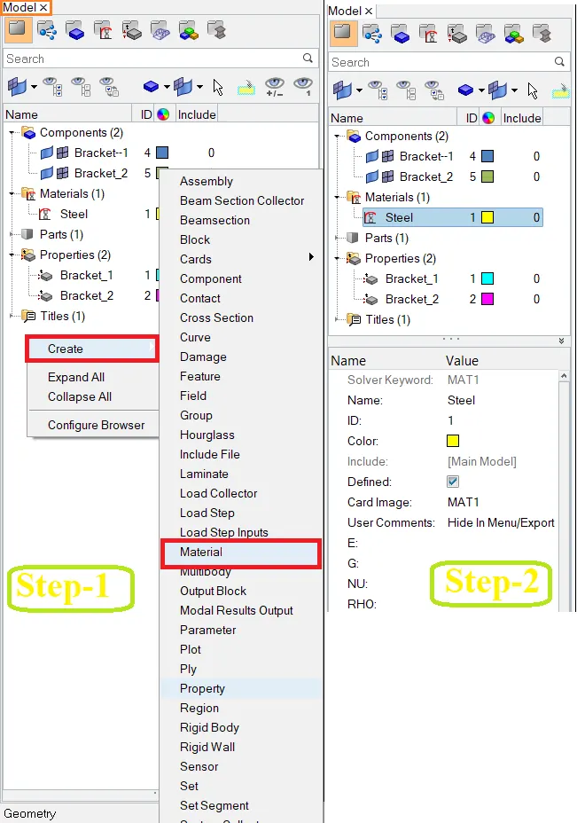
To assign material go to Model tab--> right click-->create--> material.
Then create Property for each midsurface and provide thickness of the component after that attach the material ID.
Then assign those property to their respective component ID.
Creating material will be,
Creating property for each component will be,
Assign Property to its respective component by selecting Model tab--> right click-->create--> Property will be,
Create washer cut around the holes:
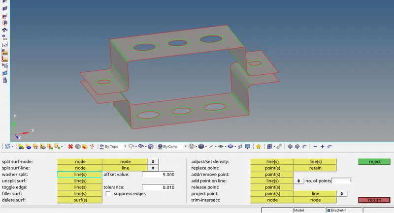
- Washer split lines are used to obtain proper mesh flow around the hole areas.
- To create washer line go to main menu--> Geom--> washer split--> lines .
- Set the Offset value as same as target elements of 5 units and then click on holes to create.
Generate the Mesh:
The midsurfaces are meshed because the nodes are required for creating 1D element.
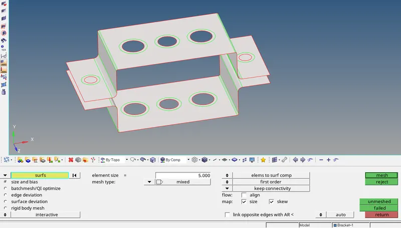
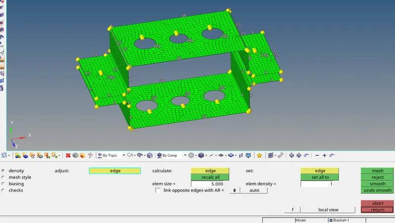
Mesh the created midsurface by selecting main menu--> 2D--> automesh--> surfs--> displayed.
Then set the target element size as 5 units, mesh type as mixed and then click create.
Deploying required Connections:
- In the FE-model Rigid, RBE3 and Spring element connections are to be performed.
- RBE2 are called as rigid which distribute the load or force equally to each and every neighbouring elements irrespective of their position and distance from th e independent node.
- RBE3 Connection distribute the load/force is exactly non unifrm. It will be reduced by distance to its neighbouring elements.
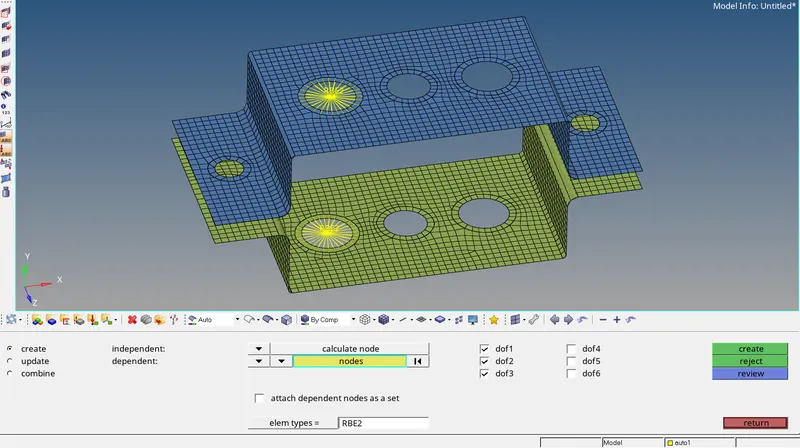
- To perform RBE2 and RBE3 connections go to main menu--> 1D--> rigids/rbe3 then change nodes as multiple nodes and constrain required D.O.F as per given then select nodes and create.
- To make Spring element connection go to main menu--> 1D--> springs select nodes and create.
- To apply mass of magnitude 10 go to main menu--> 1D--> masses provide mass value and set element type then select nodes and create.
d. & e. Apply the mass of magnitude 10 with the RBE2 link
f. Join the two components with Spring elements
Create 1D element connections:
- To create Rod connection go to main menu--> 1D--> rods and set elem types as CROD and select nodes to create.
- To deploy Beam/Bar element connections go to main menu--> 1D--> bars and set elem types as CBeam/CBar and select nodes to create.
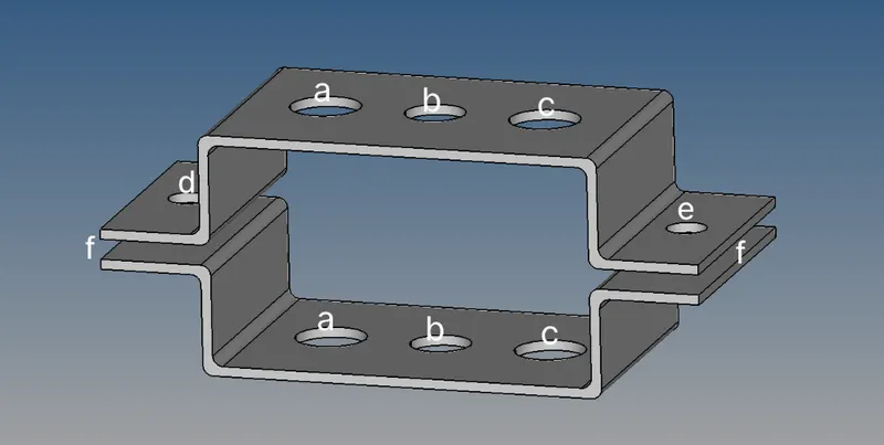
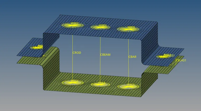
CRod, CBeam, CBar and Spring connections are deployed and masses are assigned.
Create 1D element Cross sections:
- The Cross sections has to be developed for 1D element connections to make the conversion of 2D and 3D elements.
- To create Cross sections for 1D elements go to main menu--> 1D--> Hyperbeam--> standard section--> Hyperbeam/Optistruct--> Select required cross section--> create.
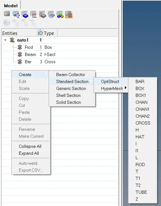
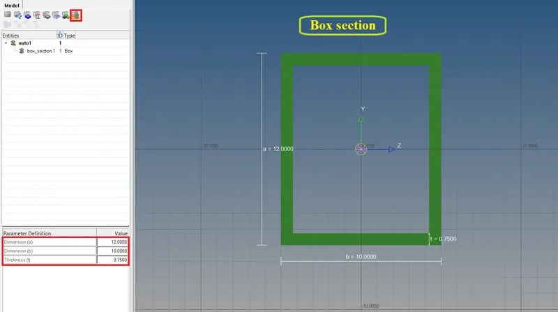
a. Rod element:- Translational DOF should be Constrained with RBE2 link
Cross-Section: BOX- Dimension a= 12 mm
dimension b=10 mm
Thickness t= 0.75 mm
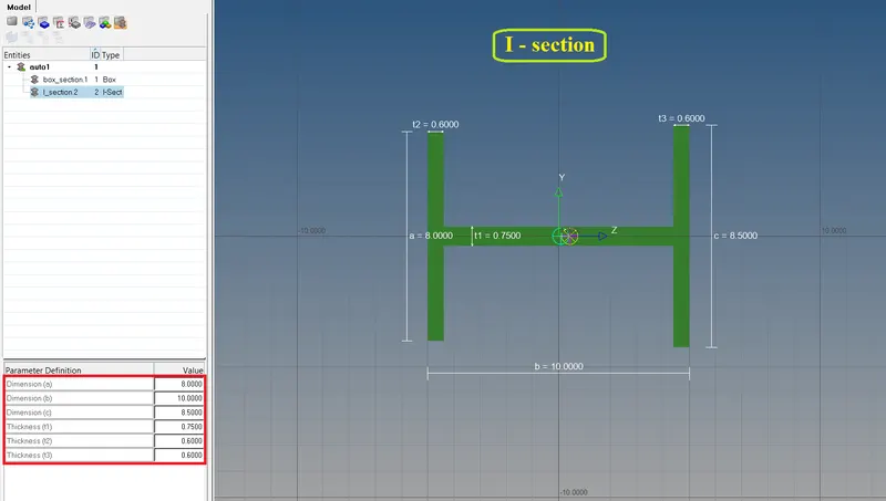
b. Beam element:- All DOF should be constrained with RBE3 link
Cross-Section: I Section- Dimension a= 8 mm
Dimension b= 10 mm
Dimension c= 8.5 mm
Thickness t1= 0.75 mm
Thickness t2= .6 mm
Thickness t3= .6 mm
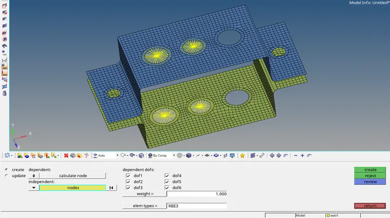
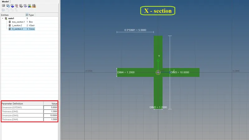
c. Bar element:- Constrain only x and y DOFs With RBE3 link
Cross-section: X section- Dimension DIM1= 5 mm
Thickness DIM2= 1.2 mm
Dimension DIM3= 10 mm
Thickness DIM4= 1.2mm
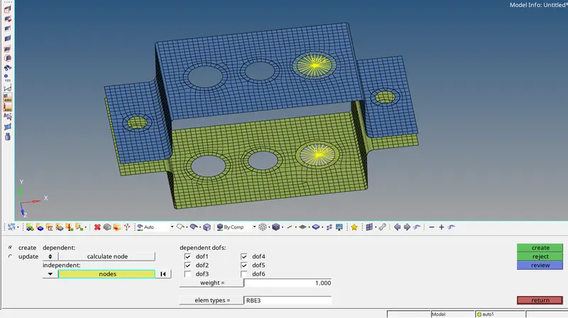
- Then create the property for each 1D element connections and set the Card image and assign to their respective Beam section.
- Then Update the Property of each 1D element connections.
Result:
fig- 1D Detailed Element Representation
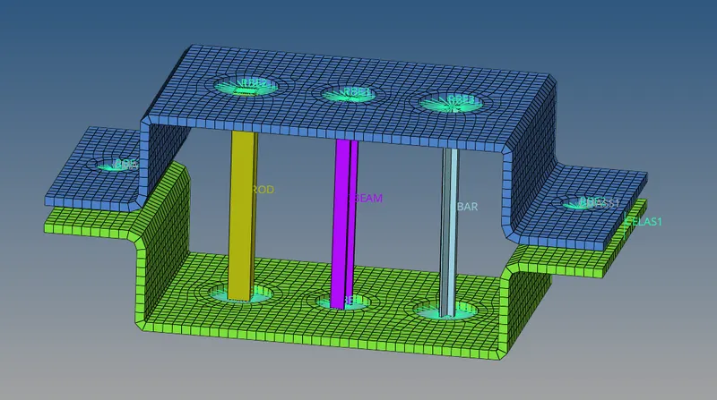
fig- 2D Detailed Element Representation