Week 3 - 2D meshing for sheet metal
ANSA July Batch
Aim:
For the given hood model the mid surface has to be created and the mesh flow to be done for the mid surfaces under the conditions of given element Quality criteria.
Objective:
- From the given hood model the geometry clean up has to be done then the mid surface to be created for all the components.
- Then the 2-Dimensional mesh flow to be created in the mid surface for each components and its features that should clear the given quality criteria.
- After meshing the mid surface with good mesh flow, thickness must be assigned to all the mid surfaces.
Steps for 2D meshing on a sheet metal:
- Cons resolution
- Topo connectivity
- Check geometry
- Measuring the thickness
- Surface orientation
- Creating mid surface
- Quality criteria & mesh parameters
- Set mesh parameters
- Cleaning the mid surface
- Generate the mesh
- Reconstruct the failing mesh flow
- Assign thickness to midsurface
Procedure:
Cons resolution:
After importing the cad geometry to Ansa by selecting file > open then select the hood model file then click open.
Select one component by switch on bulb in their properties and deselect other components by hiding.
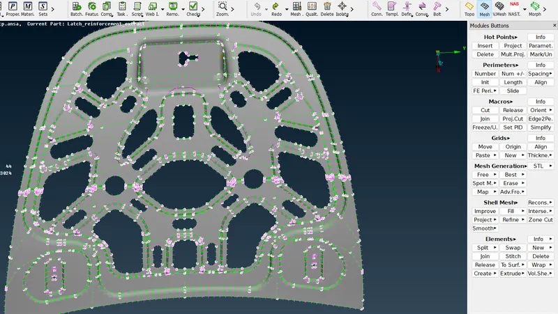
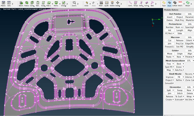
Then go to mesh module select the length in perimeter tab and select the entire entity by window box selection and press mouse scroll button as confirmation then assign the perimeter length as 5mm.
Before cons resolution
After cons resolution
Topo connectivity:
The imported .igs file might doesn't have the surface connectivity. To get that we have to do Topo over the entity by selecting Faces > Topo in Topo module select entity and press confirm.
Check geometry:
The imported cad geometry may have errors like unwanted attached cons or gaps between faces or discrepency in the model.
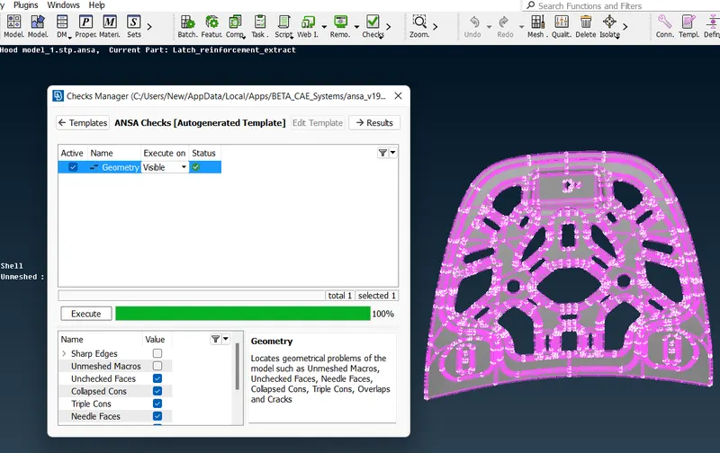
To avoid that check geometry has to be processed. In the view deck by clicking on the Checks > Geometry then press execute.
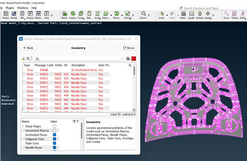
If any kind of above mentioned errors pop up in the checks geometry it can be rectified by auto fix or it can be resolve by manually fixing the entity.
Measuring thickness:
The mid surface can extracted only if the thickness of the entity is less than 5 to 6mm other tan there is no need to extact the mid surfaces.
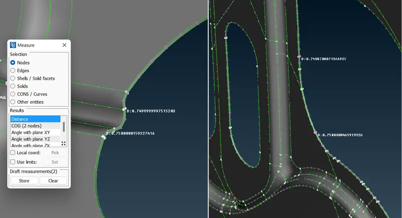
To measure the thickness of the entity go to Utilities > measure then select the nodes to find distance between the nodes or hot points or by selecting cons the distance between the cons can be identified.
Measuring thickness at various areas,
Surface orientation:
The orientation has to be done to make each side of all the faces to be in one normal direction. the yellow color represent the negative side and the grey color represent the positive side surfaces of the component.
To do that click on orient in faces tab in the topo module the component will get oriented.
Creating mid surface:
There are two types of methods available for creating the midsurface to the sheet metal components.
After identifying the given component is a sheet metal model by ensuring same thickness all over the component either the offset or skin method can be used to create the mid surface.
To do the manual mid surface select faces>offset> faces in the Topo module then select the entity by using the feature tool to select entire entity then do confirm then provide the offset value and verify at which direction the mid surface will create.
If the mid surface direction is came from selected faces to outside the surface provide negative sign to inverse the direction.
Then the offset value must be the half of value of thickness of the sheet metal component. And to make changes in options list from use existing to auto create for the property.
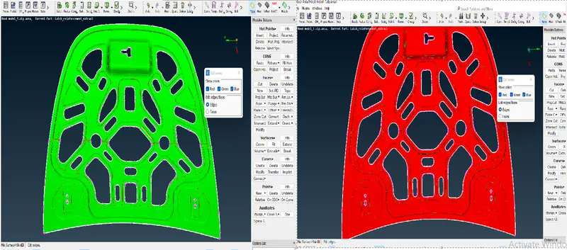
At here we are using the skin command to create the midsurface. The skin is an automatic method for creating the mid surface, by selecting faces>midsurface>skin then select any one side and give confirm.
Front and back surface of hood at skin,
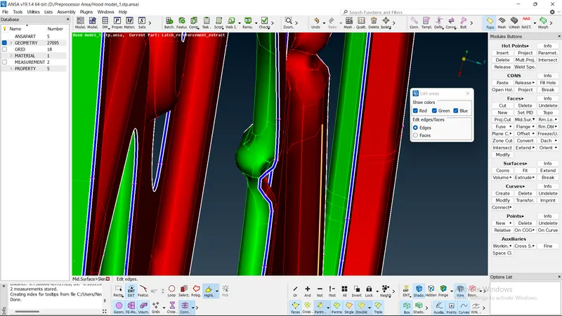
And uncheck the Delete original surfaces in the options list. Now one side of surface will be red the other side will green and the middle thickness area will be blue in color.
Then by giving confirm on offset the mid surface wil get generated.
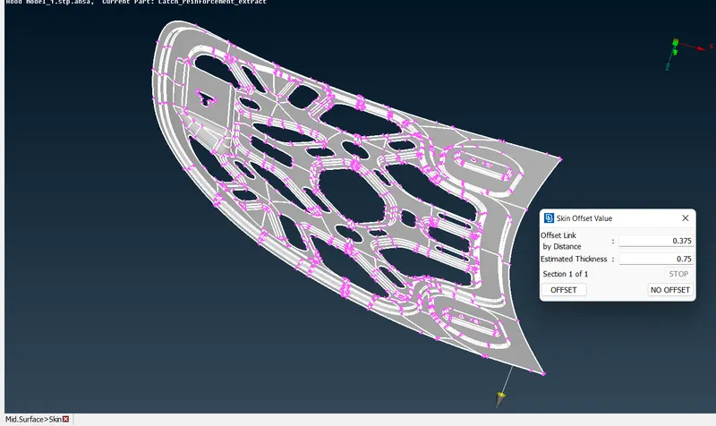
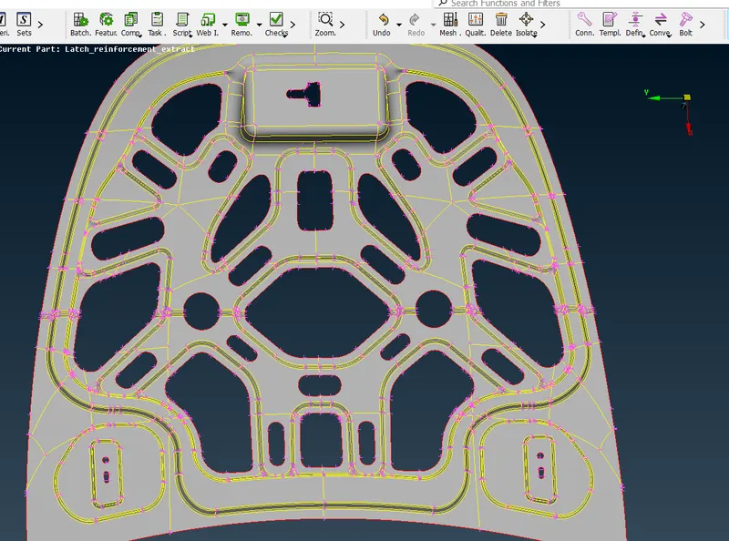
The generated midsurface will be,
Quality criteria & mesh parameters:
After creating the midsurface the quality criteria has to be set for the creating mesh that should pass some provided criteria.
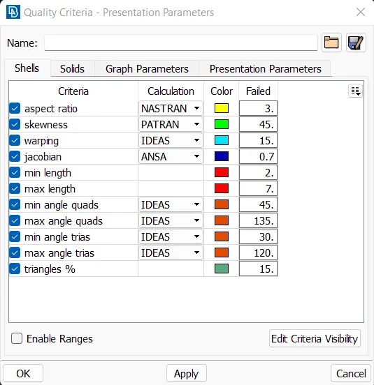
Now in the utilities tool bar click on the Quality criteria and to select some specific criteria in shell and provide the values as per the table given and click apply and ok.
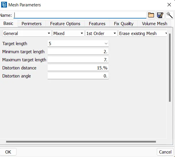
Then provide the mesh parameters by selecting mesh parameters in utilities and mention target length, minimum and maximum target length for elements then give ok.
Deleting the symmetrical midsurface:
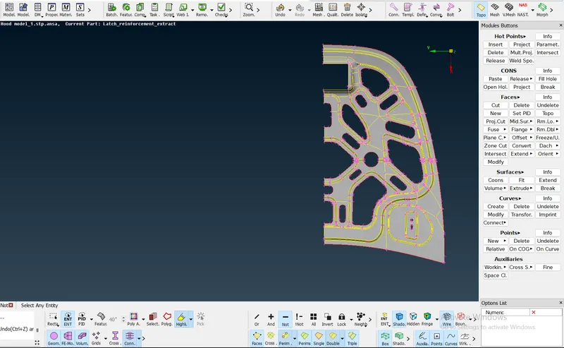
If the internal hood midsurface has divided at center except the latch top surface all the remaining surfaces are perfectly symmetrical.
The dissymmetrical part latch has to hide using boolean command Not and then by using faces>plane-cut a cut has to be created at the middle to divide it to two parts.
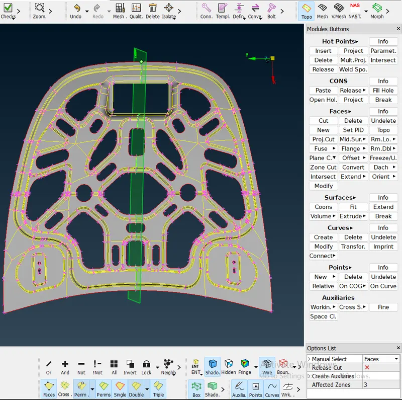
By deleting the half it will be easy to create mesh on one side and to transform it to another side to done the mesh easily on the whole component.
Cleaning the midsurface:
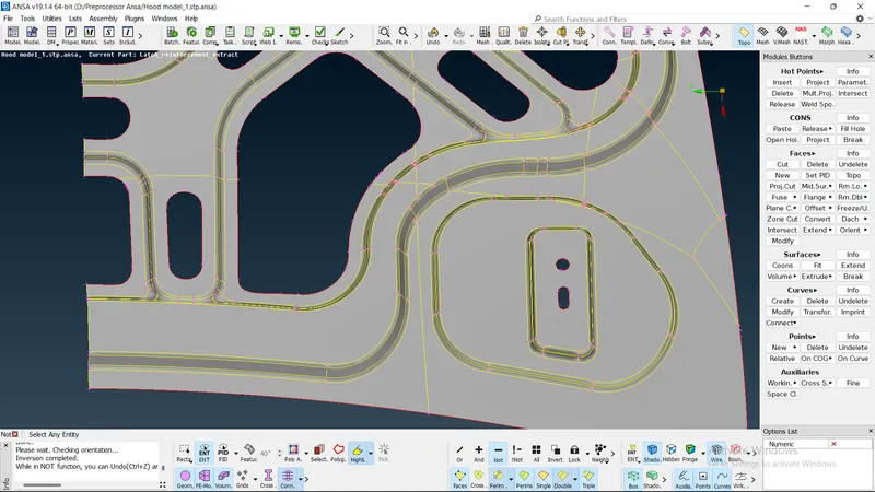
Now at entire place of the midsurface has to be check to identify if there is any minimum length between the feature lines, cons and hot points.
Before supressing the defearturing lines,
Then those lines should be suppress by joining the cons and to delete the unnecessary hot points.
After supressing the defeaturing lines,
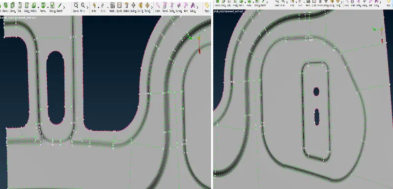
By toggling the lines the dicrepancy of the mesh elements due to the defeaturing can get avoided.
Mesh:
A mesh is a network that is formed of cells and points it can almost done in any shape and size that used to solve the partial differential equations.
The extended object has an infinite number of points and every point will have 6 D.O.F. But the Finite element method reduces the infinite geometry to finite geometry by meshing.
Elements for 2D mesh:
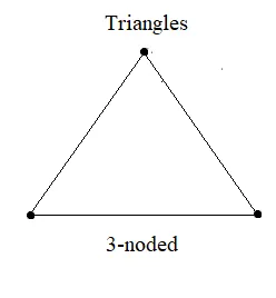
For sheet metal components two types of mesh element shapes are used.They are,
Triangles calles as tria
Quadrilaterals called as quad
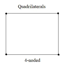
Both of them are using at a same time by using mixed for element type in option list bygenerating the mesh.
Generate the mesh:
After customizing the tolerance lines deleting the symmetrical part use faces>cut to make a cut of faces into desired macro area for doing mesh then click on the Mesh Generation > Best > select and select the faces to mesh.
Then do the same for all over the faces of area on the midsurface the mesh to be generated.
Reconstruct the failing mesh flow:
After doing mesh using the Mesh generation>Best will provide poor mesh flow. To make it better mesh flow use shell mesh>reconstruct to obtain better mesh flow.
The various methods to reduce trias and improving the mesh flow by moving the trias are,
If two trias in opposite direction are facing together it can be neglect by using the Elements>split>shells in that split by edges are used combine the opposite facing trias together.
If trias are at the edge it can neglect by paste nodes to move backward.
By using swap edges to move the trias to left orright side to deviate from the corners.
After moving the trias use smooth in shell mesh to improve the mesh flow in order to adjust the disturbed nodes.
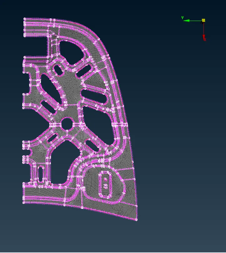
The final meshed half midsurface,
Transform symmetry surface:
After completing of generating the better mesh flow on half symmetrical area of midsurface use transform > copy then select entity and click on symmetry to transform the other side FE geometry.
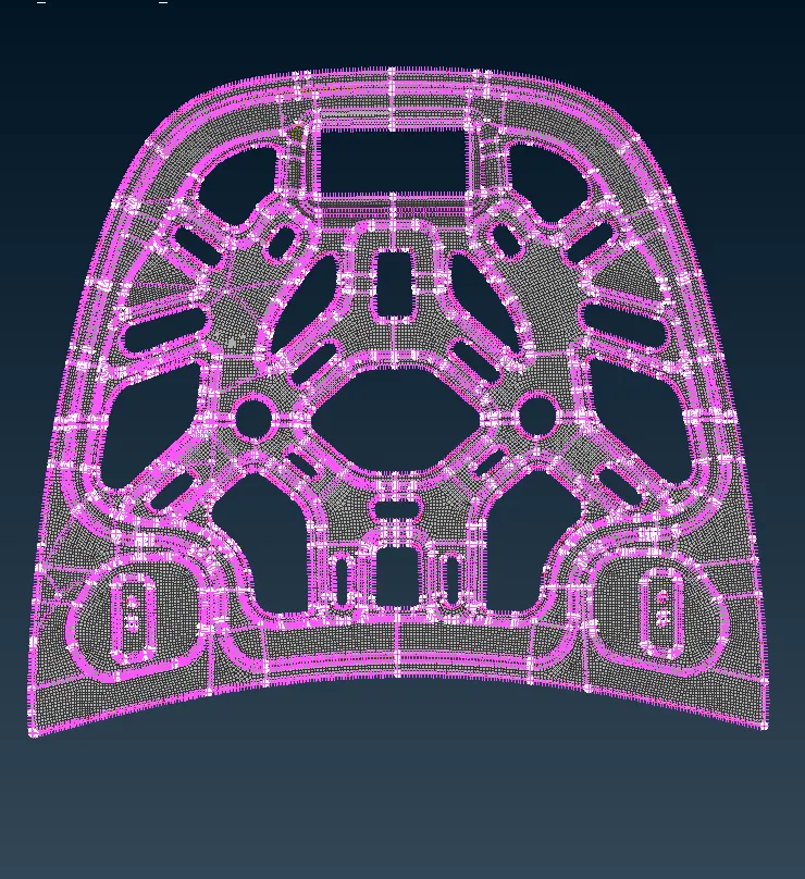
The final meshed midsurface will be,
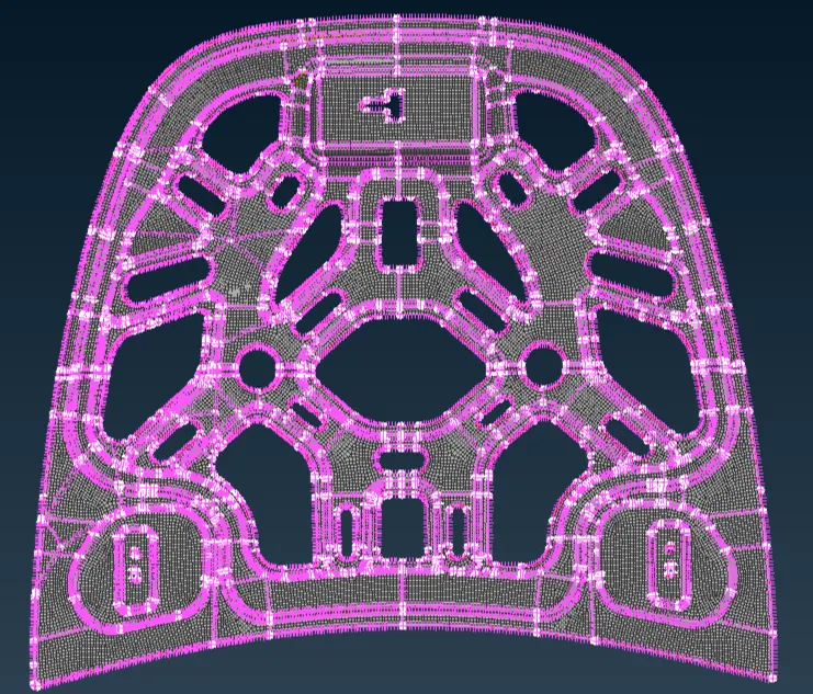
Assign thickness to midsurface:
Then open quality criteria and click on presentation parameters and by selecting Draw shell as solid to make thickness to the meshed midsurfaces.
As per the same way the process has to be followed for creating meshed midsurfaces for all other models of the hood.
Result:
Hence the mid surface are extracted from the parent component.
The surface deformations in the geometry are resolved.
The features have been captured properly.
A good mesh flow have been achieved with no off elements failing for quality criteria.
Hence the tria percentage with 2.81% have been achieved.