Week - 4 - 2D meshing for Plastic components
AIM:
The FE-model has to be created for the given model Plastic bottle cap by creating midsurface and thickness has to be assign for the given component using the ANSA preprocessor tool.
OBJECTIVE:
- Check for the geometrical errors and to create the midsurface for the given plastic components.
- Mesh the extracted midsurface with good mesh flow at given quality criterias and to obtain zero OFF elements.
- Assign PID or Property ID and thickness for all the midsurfaces and finally activate Draw shell as solid for the midsurfaces.
COMPONENT PROPERTIES :
Materials which is having less than or equal to 6mm can be meshed by creating midsurface with 2D Meshing. If it is above than 6mm there is no need to create the midsurfaces.
- In 2D Meshing, we can classify the materials into two types.
- Sheet Metal Component
- Plastic Component
- The material which is having Linear Thickness throughout the Body is known as 'Sheet metal'.
- The material which is having Non Linear Thickness is 'Plastic Material'.
PROCEDURE:
- CAD SET UP
- CAD Geometry
- Model Clean Up
- CAD MODELING
- FE-model
- Meshing
- FINAL CHECK
- Attain proper Mesh
- Achieve zero OFF element
- Assign Thickness to Midsurface
PHASES:
At each phase it will explain about the process fo extracting Midsurface, proper mesh flow, reducing OFF ELEMENTS and assigning thickness to midsurfaces of the given Plastic Bottle Cap model.
Phase-1 Fixing CAD geometry
Import CAD:
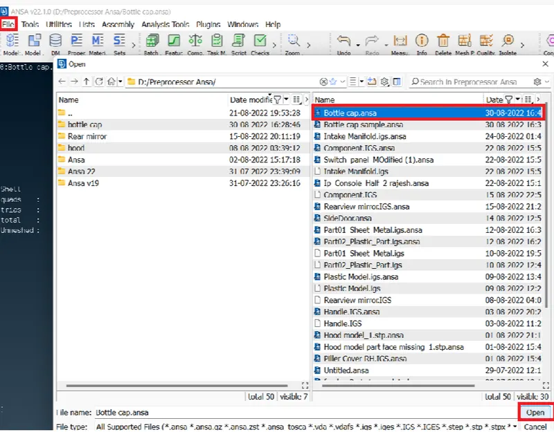
The given Cad model has to be import in ANSA preprocessor tool by File>open select the file should be in .igs or .stp format and then click open.
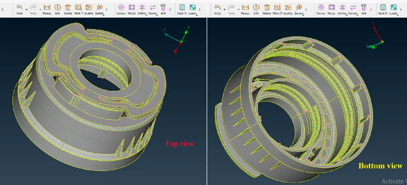
The imported Plastic Bottle Cap model will be,
Cons resolution:
The cons resolution will improve the resolution of the component are by selecting entire entity on Perimeter>length in classic mesh deck.
Topo Cleanup:
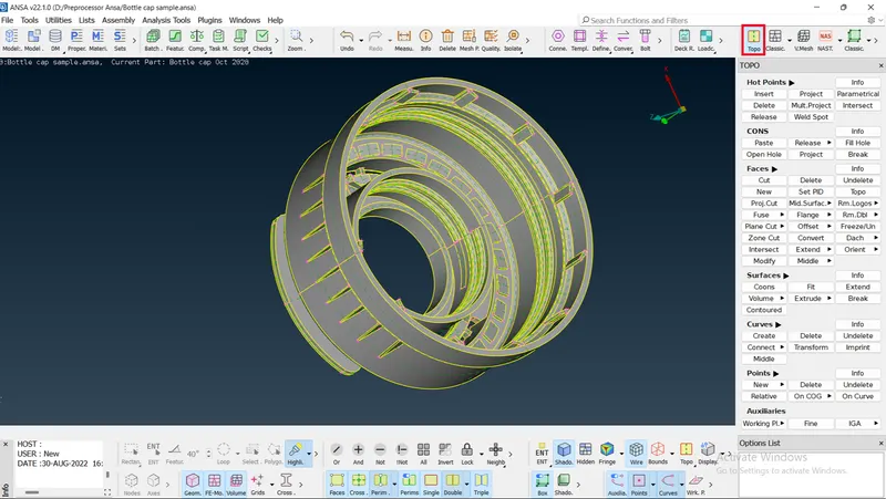
The Topolgy has to be done if the imported geometry doesn't have the surface connectivity. If all the surfaces are connected perfectly then there is no need to do topology.
The Topology is not required for this component because the model has no gaps or well connected to each other surfaces.
The surfaces of the Plastic Bottle Cap model is in well Topoed,
Orientation:
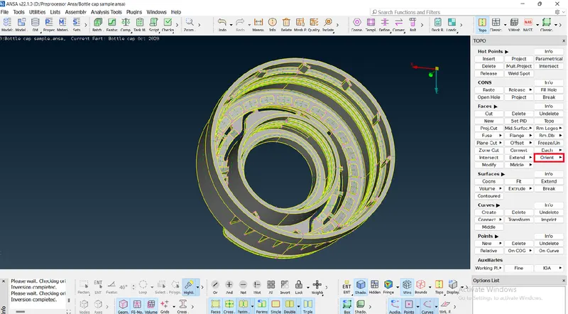
The orientation to be done to make all the faces of surface to be in one normal direction.
At here all the faces of surfaces are in oriented, so there is no need to do orient again.
Checks geometry:
The imported model can have geometry errors like unwanted attached cons or gaps between faces or discrepency.
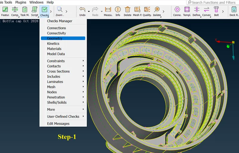
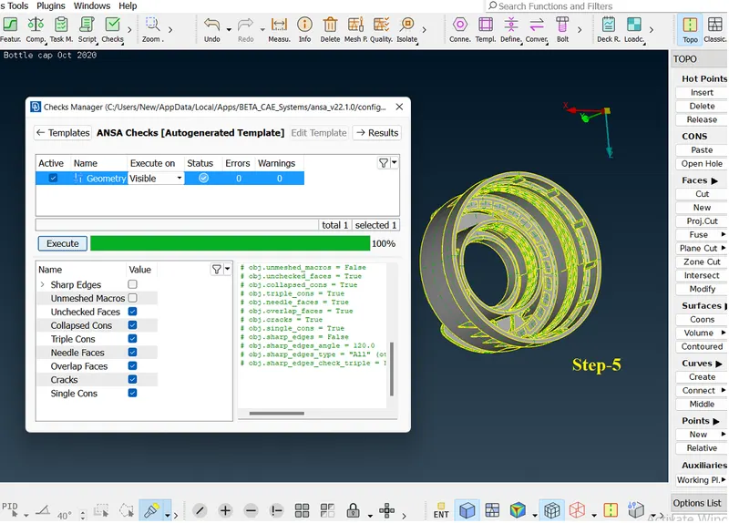
To solve Checks geometry has processed. In the tools deck select Checks>Geometry then click Execute.
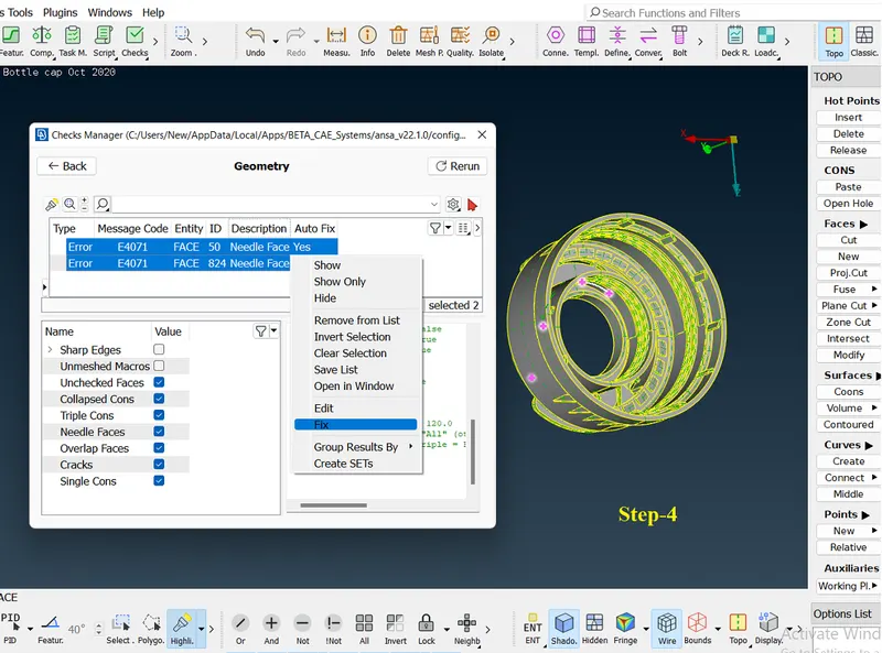
In Checks manager there is an option called Auto Fix that will fix the error which can be fix automatically.
Measuring thickness:
The thickness of the component has to be measured to identify if the model is having uniform or variable thickness.
The thickness can be measured by using measure tool in Utilities deck.
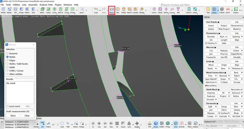
After measuring in different places, it is identified that the component having variable thickness at less than 6mm it will be concluded that the model is a plastic component.
Phase-2 Elemental Quality criterias
Mesh Parameters:
In utilities tools click on mesh parameters provide the values for target length and minimum target length as per the given quality criterias.
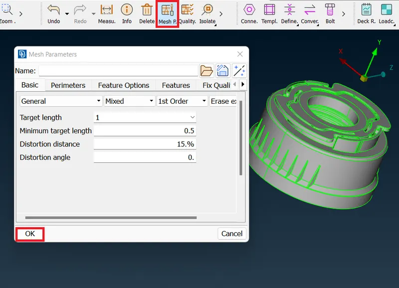
After providing mesh parameters values click ok.
Quality criterias:
Now provide the quality criterias to set the mesh that should come under the given spcific criterias.
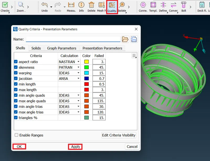
After providing Quality criterias click Apply and Ok.
Phase-3 Extracting Midsurface:
Creating Midsurface:
The CAD geometry had prepared. Now the Midsurface has to be create for the component.
There are two methods to create the midsurface for plastic model. They are,
- Manual Method
- Automatic Method
At here the Casting option is used in Automatic method to create the midsurface.
Casting option will save lots of efforts in extracting midsurface at various thickness areas.
Before creating Midsurface
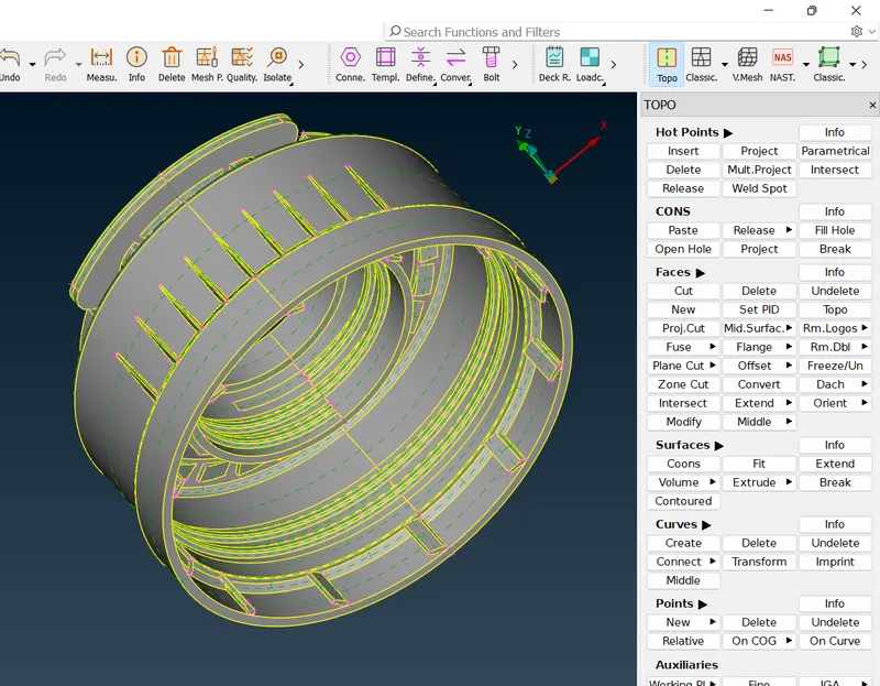
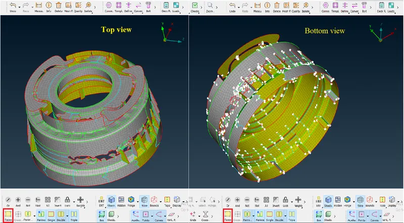
To do Casting option select Mid.Surface>Casting in Faces module.
Provide the value for Minimum thickness by measuring at different areas and click Ok.
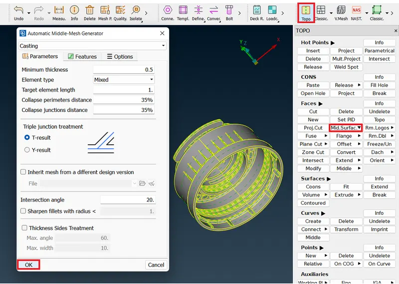
After creating Mid.Surface
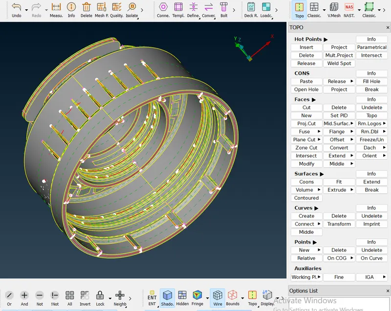
Extracted Midsurface
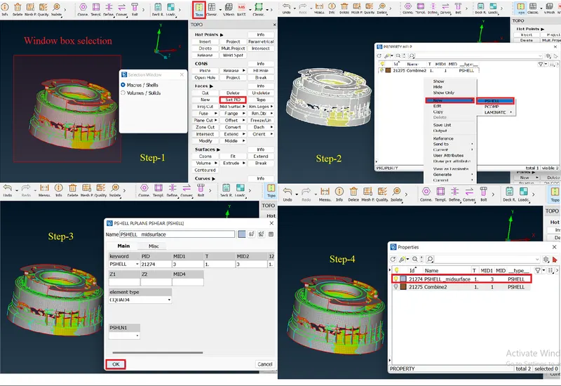
Set PID:
The PID or Property ID has to be set for the extracted Midsurface by selecting Set PID option in Faces group in Topo module.
Then select the midsurface component by window box selection and give confirm by mouse scroll button.
In Property prompt box give right click and select New>PSHELL.
Now provide Ok in new PSHELL property ID.
Double tap on the newly created property ID in Property prompt box to set the PID.
The steps for setting the PID or Property ID will be followed as,
Distorted surfaces:
In midsurface plane there are some areas get distorted or deformed that are not captured perfectly by Casting as per the Parent geometry.
Some axamples of those distorted areas are,
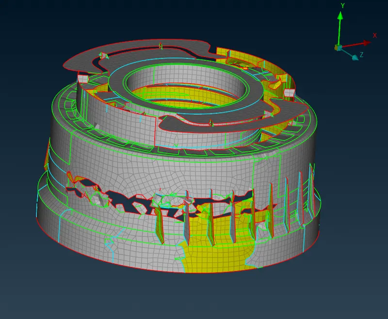
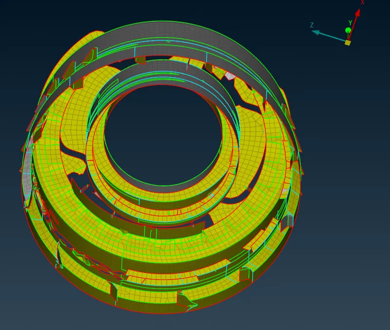
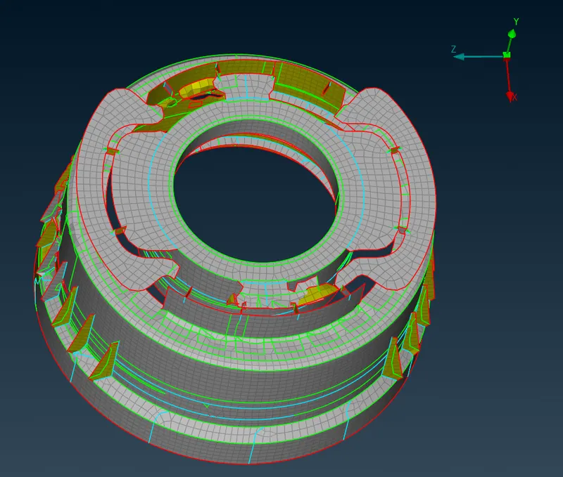
Now to capture those deformed areas Align manager has to be used to define the distorted areas using the Parent geometry.
Phase-4 Redefining the surfaces:
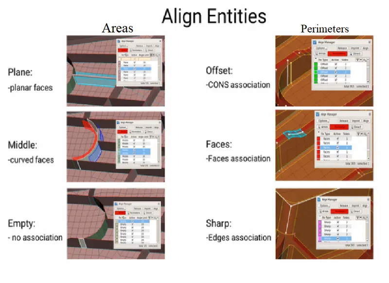
Align Manager:
The Align manager are used to recorrect the wrong definition or undefined areas and perimeters for the distorted surfaces.
Capturing missed Teeth:
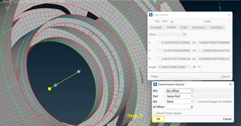
There are 26 no. of Teeth are to be capture on the plane surface. All those teeth are having same symmetrical dimensions.
So it can be easily captured by creating a single tooth and to be translate by rotating using Transform tool.
Steps followed to capture the Teeth:
- Create two Midpoints at below and above of the Teeth capturing plane by selecting two symmetrical points of any circular entities using Points>On COG>Points in Topo module.
- Using parent geometry create Middle curve of a Tooth by selecting Curve>Middle in Topo module.
- Project the curve in midsurface by using Shell Mesh>Project>Perimeters in Mesh module.
- Create new surface between the Curve and Project line using Shell Mesh>Fill in Mesh module.
- Now using two midpoint as Axis for X and Y location For rotating the Tooth by Transform>Copy>Rotate to create 26 no. of teeth.
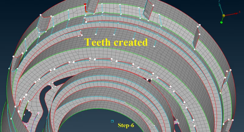
Thread capturing:
As same by creating the Middle curve and project at an entity and then create new surface by Fill command to create the thread areas.
Phase-5 Improving Mesh flow & its Quality:
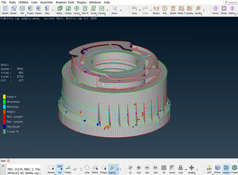
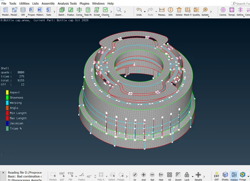
After finishing the cleanup and definition corrections in the Midsurface, now its time to improve the mesh flow and to achieve zero OFF elements.
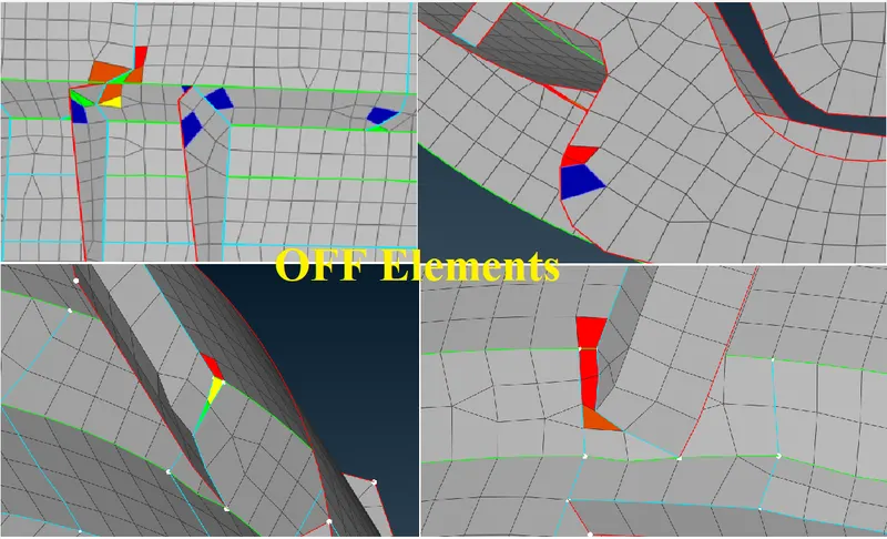
In some areas OFF elements are not resolved due to Triple cons are present near to the Features.
Before improving Quality criterias:
After improving Quality criterias:
Phase-5 Assigning Thickness:
Various thickness has been assigned to each individual areas of the midsurface by using Grids>Thickness>Convert in Mesh module.
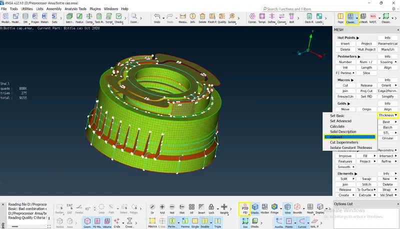
Draw shell as solid are also activated.
Conclusion:
- The Midsurface has been created and meshed with minimum neglegible OFF elements.
- Good mesh flow also achieved with no trias touching the circle and at free end are maintained.
- No rotating quads and no opposite quads are kept in the FE-model.
- Thickness has been assigned and Draw shell as solid are also get activated.
- All feature lines are captured at meshing.
- Missed Ribs, Thread and Teeth has been captured properly.
Learning Outcomes:
- Learned to extract midsurface using Casting option and providing definition using Align manager.
- This component is some what tricky and got excited to do meshing like this model.
- Especially Align Manager and Thickness assigning are interested things to perform.
- It gives the confidence to perform at any complicated models easily.