Week 6-Meshing of Hood Challenge
AIM:
- The midsurface has to be generate with proper mesh flow from the given Automotive Inner panel Hood component within the given elements Quality criterias and assign thickness by using the Hypermesh preprocessor tool.
OBJECTIVE:
- For the given component, check the geometrical errors and generate the midsurface from the model.
- Then do proper mesh flow on the extracted midsurface with low tria concentration.
- The meshed element should clear the given quality criteria.
- After meshing the midsurface, thickness has to be assigned.
COMPONENT PROPERTIES :
Materials which is having less than or equal to 6mm can be meshed by creating midsurface with 2D Meshing. If it is above than 6mm there is no need to create the midsurfaces.
- In 2D Meshing, we can classify the materials into two types.
- Sheet Metal Component
- Plastic Component
- The material which is having Linear Thickness throughout the Body is known as 'Sheet metal'.
- The material which is having Non Linear Thickness is 'Plastic Material'.
Inner panel Hood:
The hood or bonnet is the hinged cover over the engine of motor vehicles. Hoods can open to allow access to the engine compartment on rear or front engine for maintenance and repair.

figure- Open hood car
PROCEDURE:
- CAD SET UP
- CAD Geometry
- Model Clean Up
- CAD MODELING
- FE-model
- Align Entities
- Meshing
- FINAL CHECK
- Attain proper Mesh
- Achieve zero OFF element
- Assign Thickness to Midsurface
PHASES:
At each phase it will explain about the process fo extracting Midsurface, proper mesh flow, reducing OFF ELEMENTS and assigning thickness to midsurfaces of the given component.
Phase-1 Fixing CAD geometry
Import CAD model:
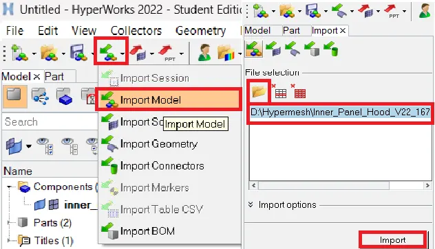
The given CAD model is in .STEP format.
To open the model select Import model--> File selection window-->select file--> file type as hm--> Import.
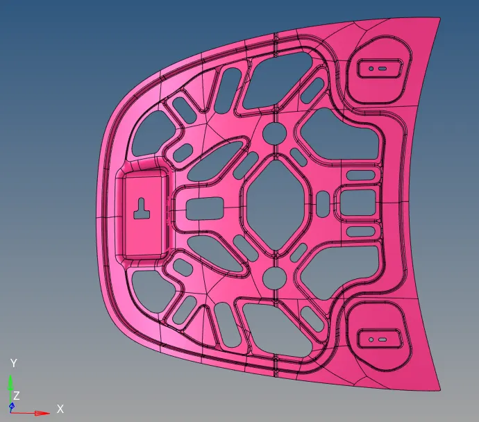
The imported CAD model is an Hood component in the Graphical window will be,
Measuring thickness:
- The thickness of the component has to be measured to identify if the model is having uniform or variable thickness.
- To measure the thickness go to main menu--> Geom--> Distance then select points to measure.
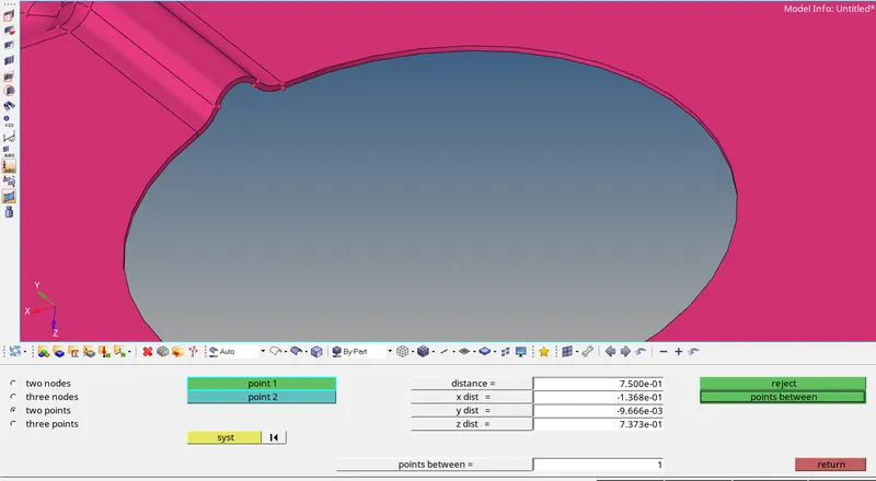
- The measured distance shows the component has uniform thickness of less than 6mm, it confirm that the model is a Sheet metal component.
Deleting the solid component:
Before creating midsurface the solid surface has to be removed from the component. To do that select Delete--> solids--> all --> delete entity to remove the solid from the component.
If the component only have the surfaces, then there is no need to perform deleting the solids.
Topology cleanup:
- Geometry cleanup has to be done before generating the midsurface for meshing.
- The imported model can have geometry errors like surface patch up, unwanted attached cons, free edges or discrepency, etc.
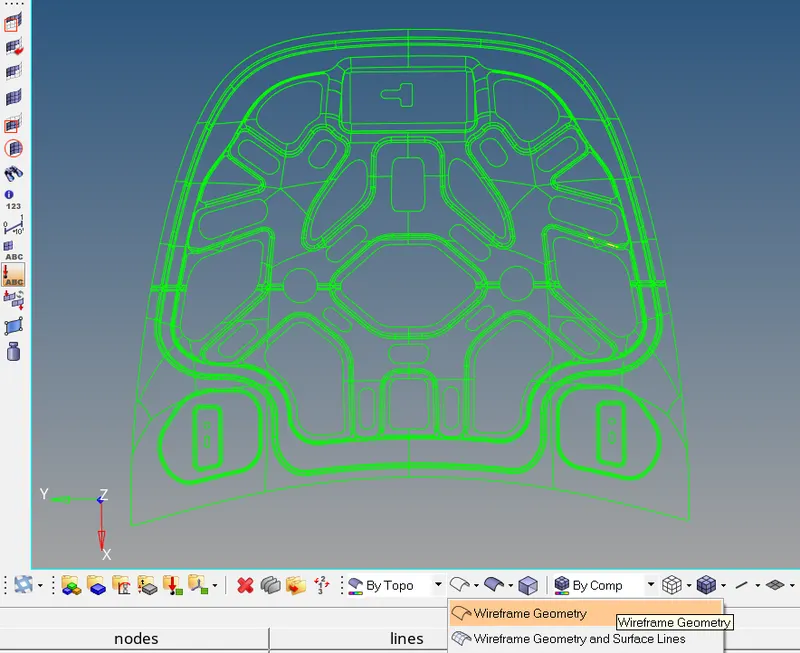
- These errors can manually rectified by visually inspecting the model in wireframe mode to identify to solve it .
The CAD Geometry in wireframe mode will be,
Phase-2 Extracting & cleaning Midsurface:
Creating Midsurface:
- The CAD geometry had prepared. Now the Midsurface has to be create for the component.
- There are two methods to create the midsurface for plastic model. They are,
- Manual Method
- Automatic Method
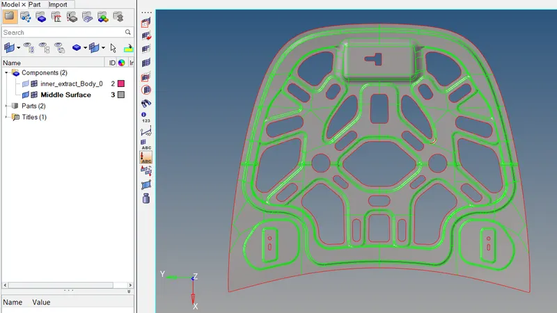
- At here the Skin offset extraction is used in Automatic method to create the midsurface.
- The midsurface is generated to simplify the CAD model and to obtain the similar simulation analysis reults in shorter time.
- Midsurface is a neutral phase that is the conversion from 3D cad model to 2D cad in midsurface generation.
- To perform Skin offset auto-midsurface select Geom-->midsurface-->auto mid-->extraction options-->skin offset and then select auto extraction-->surfs-->displayed-->extract.
Assign Material & Property to the Components:
To make the 2D midsurface as representation of 3D CAD model assign material and its thickness of the component.
To assign material go to Model tab--> right click-->create--> material.
Then create Property ID for each midsurface and provide thickness of the component after that attach to the material ID.
To create PID to their respective component by selecting Model tab--> right click-->create--> Property.
Then assign those property to their respective component ID.
Setting up the material ID will be,
Phase 3: Assign Elemental Quality criterias:
Quality criterias:
- Every developed product will undergo some Quality check during analysis to know its deformation stability before it produced.
- If its not pass the quality criterias then boundary conditions applying load setup analysis are not feasible. So the elemental quality checks are performed.
- The customizable colours for the quality criterias will show which are the elements are being failed for its criteria.
- Those elements are must be corrected manually to the given criterias.
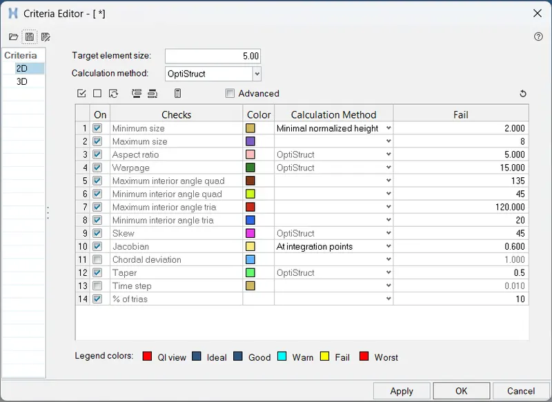
- Now provide the quality criterias to set the mesh that should come under the given specific criterias.
- To set go to Menu bar-->Preferences-->Criteria file settings
Deleting the symmetrical surface:
If the midsurface has split at center except the latch area all the remaining surfaces are perfectly symmetrical.
The Asymmetrical part latch has to be hide using Mask after that cut the part into two symmetrical surfaces.
To perform cutting the surface go to Geom-->surface edit-->trim with surfs/plane-->with plane then select surfaces and provide vector to split the surfaces.
Then delete either side to make the model simple to create mesh on one side and reflect it to another side to done the mesh easily on the whole component.
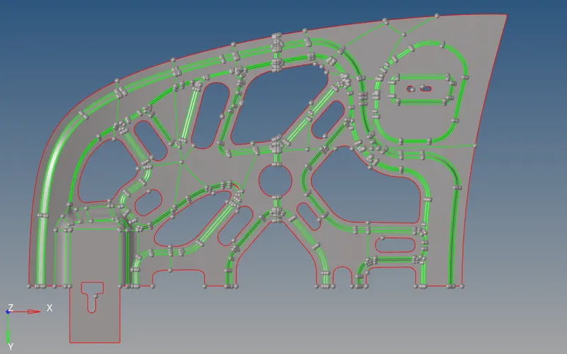
After deleting the half side the midsurface will be,
Cleaning the midsurface:
- Now in the midsurface there will be some unwanted feature definitions like minimum length between the feature lines, cons, construction lines and hot points.
- These unwanted definition errors are must be cleared by toggling and removing points before creating the mesh to obtain better mesh flow.
Creating Temp nodes:
- After cleanup the midsurface, create the temparory nodes for the failing elements.
- To create temp nodes first mesh the entire midsurface. To do select 2D-->automesh and set Element size as 5mm and mesh type as mixed and give mesh.
- Now go to 2D-->quality index-->cleanup tools-->smooth and select elems-->displayed to perform smooth.
- Smooth operation will arrange the elements to adjust the alignment to reduce the fail elements.
- Then click save failed to save the failing elements.
- Now go to Tool-->mask-->elems-->retrieve-->mask-->reverse-->return.
- Then go to Geom-->Temp nodes-->nodes-->displayed-->add-->return.
- Then Unmask and delete all the elements to find out the temp nodes for failing element lines.
After creating the temp nodes in the midsurface it will be,
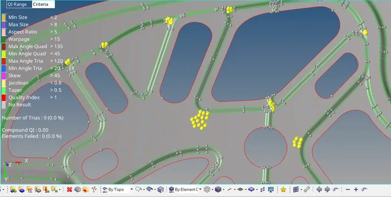
- Now correct those areas to obtain the good mesh flow.
Phase 4: Meshing the midsurface:
- A mesh is a FE-method to discretize the model into finite number of nodes and elements.
It can be classified into two types
- 2D - Structural mesh
- shell mesh (Tria and Quad)
- 3D - Unstructured mesh as well as structured
- solid mesh (Tetra and Hexa)
- Tetra - Unstructured
- Hexa - Structured
- Here 2D shell mesh has to be perform because the component has thickness of less than 6mm of sheet metal component.
- To perform mesh go to 2D-->automesh and set Target element size= 5mm and do mesh.
- Then to find the elements are failing, change the view into By element quality.
- If any element fails for quality then GO to --> 2D --> Quality Index --> Cleanup tools.
- Then use element cleanup tools like place node, swap, split trias, combine trias, drag trias, element optimize to correct the failing elements.
- Opposing trias, trias at free edge and falling on perimeter are must be eliminated.
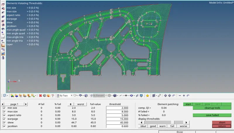
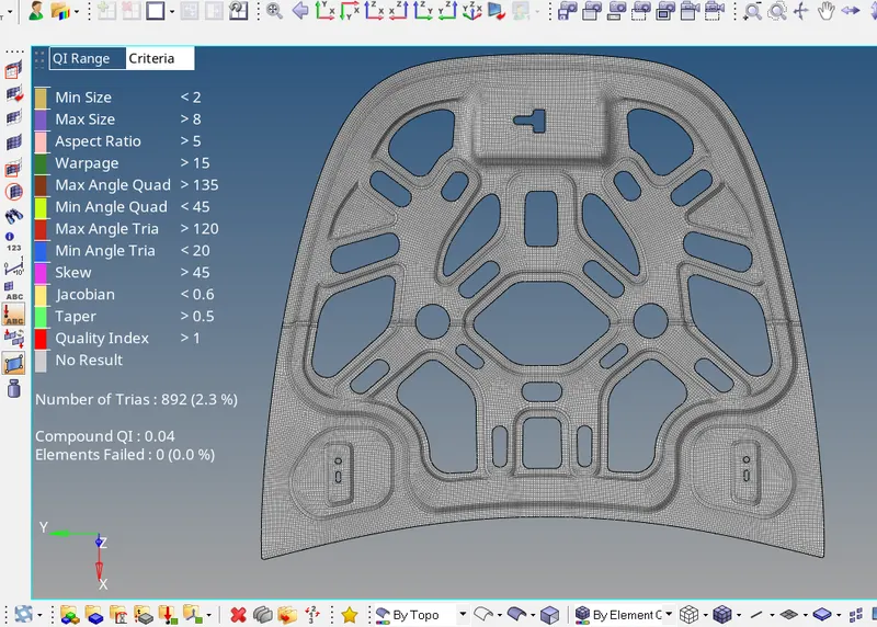
- The above imaage shows that all the elements attain the given criteria and there is no elements failing for the quality.
Reflect symmetrical midsurface & FE-mesh:
- Now reflect the half mesh to other side symmetrical area as per the parent geometry.
- Before performing symmetrical transform first mask the asymmetrical FE mesh.
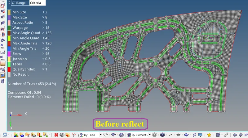
- Then execute transform by selecting Tool-->reflect-->elems-->displayed-->elems-->duplicate-->current comp and provide vector and base then click reflect to do transform.
- Now Unmask the assymetrical FE mesh.
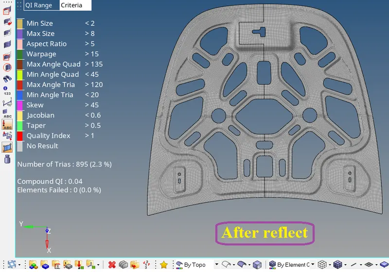
- After reflecting the symmetrical mesh there will be some free edges and nodes are musted be joined to their respective nodes.
- To join those edges go to Tool-->edges-->elems and select the elements and click preview equiv then check the attaching edges and give equivalence to join.
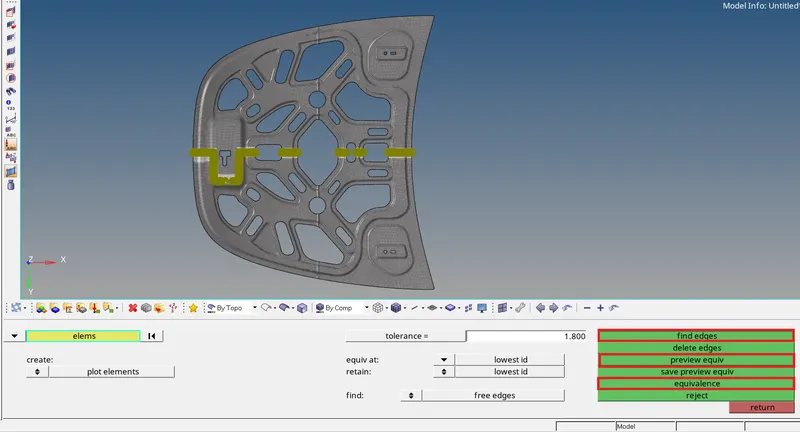
- Even though using equivalence there will be few edges are not able to attach are must be resolved manually by identifying free edges and connect them by using 2D-->replace.
After correcting the free edges the final FE-mesh will be,
Phase 4: Check list:
After attaining the good mesh flow, there will be few checks have to be performed.
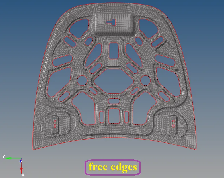
- Check for free edges
- Go to Tool --->edges-->elems-->displayed and click find edges then delete the unwanted edges.
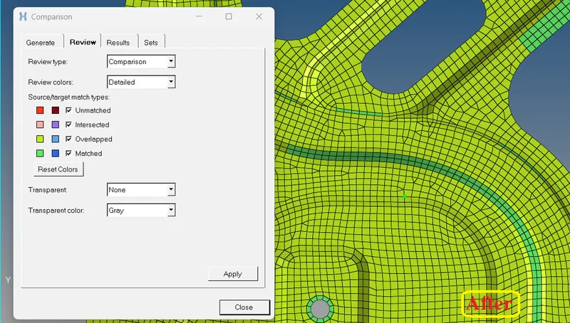
- Check for comparison
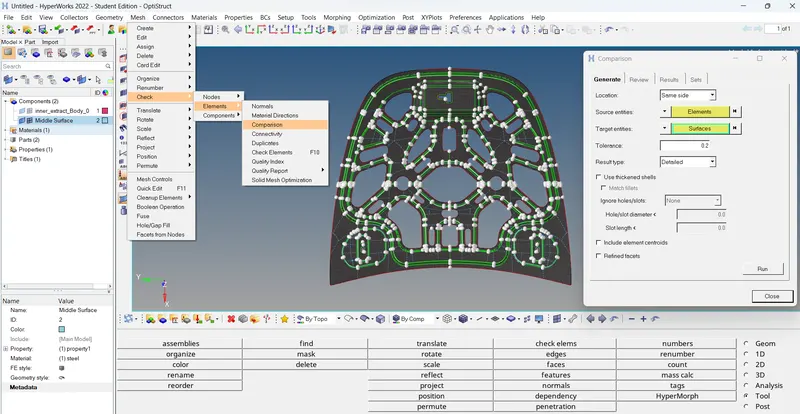
- Comparison helps to find that the elements are captured proper to the geometry surface.
- To do go to the main menu bar select Mesh-->Check-->Elements-->Comparison-->(Source: elements, Target: surface and Tolerance: 0.2) then proceed Run.
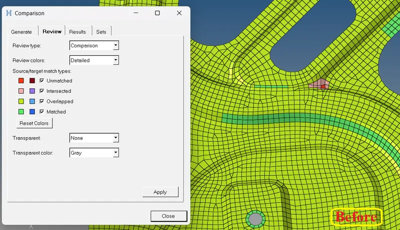
Unmatched comparison elements must be corrected by using Tool-->Project-->to surface then select unmatched elements-->surfaces-->vector-->project.
- Check for penetration & Intersection
- This check will be done for whole assemblies.
- Go to Tool --->Penetration.
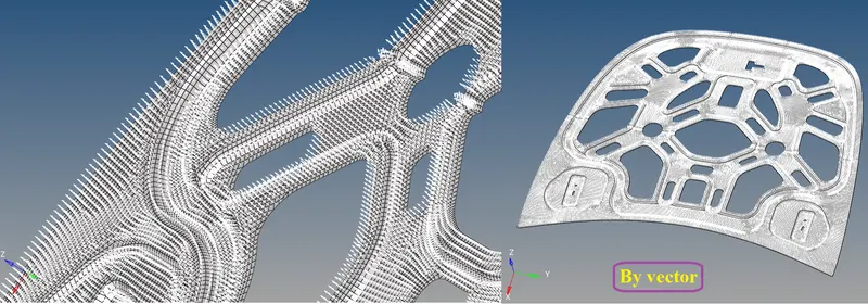
- Check for Normals
- This will help to identify all the elements are in same normal direction.
- It means if force applied to it all of these elements will act in one normal way.
- To do go to Tool-->normals-->elements-->displayed 2D elems-->display.
- If there are some improper elements then select those elements and reverse it to make it proper.
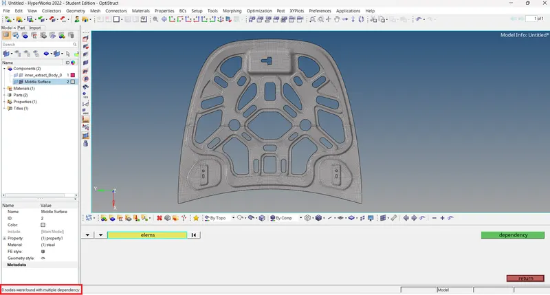
- Check for Dependency
- To do select Tool-->Dependency
FINAL RESULT:
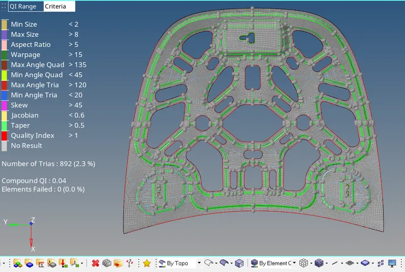
- Finally achived Trias with 2.3% and zero OFF Elements.
- Attained good mesh flow and opposing trias, trias at free edge and falling on perimeter are eliminated.
- No Rottating Quads are keep maintained with low tria concentration.
- No any other Feature Lines missed while meshing.
- After meshing the midsurface, thickness has been assigned.
LEARNING OUTCOMES:
- Understood to perform geometry cleanup for any complex sheet metal & BIW components.
- Can generate midsurface for any complex sheet metal & BIW components.
- Able to resolve and achieve the elements to their quality criterias for any complex sheet metal & BIW components.
- Work with HYPERMESH with a flow.