Week - 8 - Morphing
AIM:
To practice all the morphing techniques and to increase the height of dog houses and ribs on the given model using the ANSA preprocessor tool and mention the applications of morphing in various industries.
OBJECTIVE:
- To perform all the Morphing techniques using Box morph on the given component Floor panel Model-1.
- To increase the height of Dog houses and Ribs on the given component Hand rest model-2.
- Then to discuss about the applications of morphing in various industries.
MORPHING:
Abstract of Morphing:
- Morphing is a useful tool for doing shape transformation quickly to a new form.
- The geometry of a given concept model can be modified to required proportions to create new designs on the components.
- Morphing allows users to work on the FE mesh directly reducing the time taken to go back to the designer to update the CAD geometry.
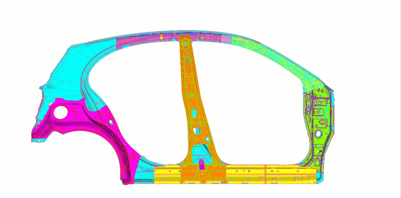
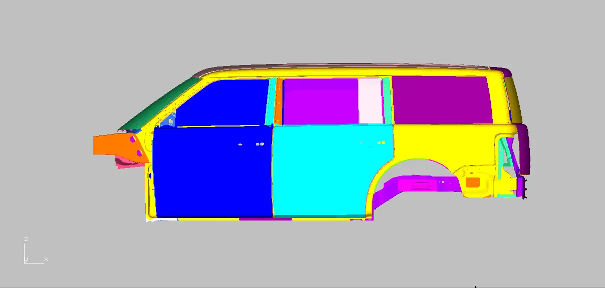
Morphing can be perform directly over the FE-model or on the CAD geometry are represented in the above image.
Morphed on FE-model:
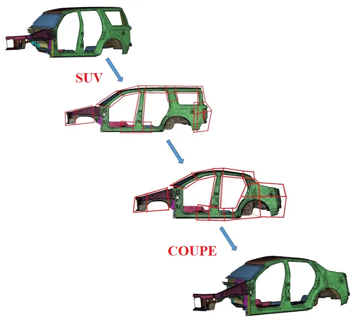
Modifying the car variant by Morph:
Time consumption on updating CAD Geometry over Conventional and Morphing method flow chart:
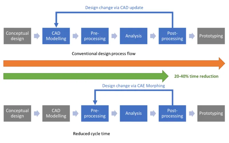
Cycle time reduction on Morphing:
- Morphing is the easiest way to upgrade the parent geometry with lesser in time to perform FEA.
- In conventional method of updating CAD geometry takes more time to perform on CAE.
- Minimizes time spent on design modification by working directly at the mesh level.
- Easy transformation of CAE models from the original design to a new concept.
- It keeps the connections (contacts, boundaries, loads, bolts, welds, etc) from the current to the updated model.
Types of Morphing techniques:
Box Morphing:
The Box morphing are performed by creating a morph box on the entity at a specic areas at where the user intends to change the shape of the model.
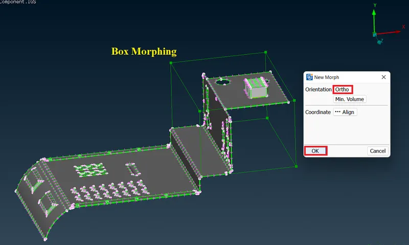
The movement of the Morphing boxes control node points defines at which areas the shapes are need to change or upgrade to both FE-model or CAD geometry at a time.
Here the Ortho coordinates are acted according to the Global axis to the selected specific entity.
Direct Morphing:
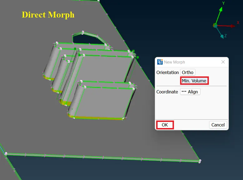
Direct morphing Feature allows to user to perform morphing directly on the specific region that need to morph on local axis without developing a morph boxes.
Single part are smaller areas can morph by using the local axis as minimum volume of the entities.
Geometry Morphing:
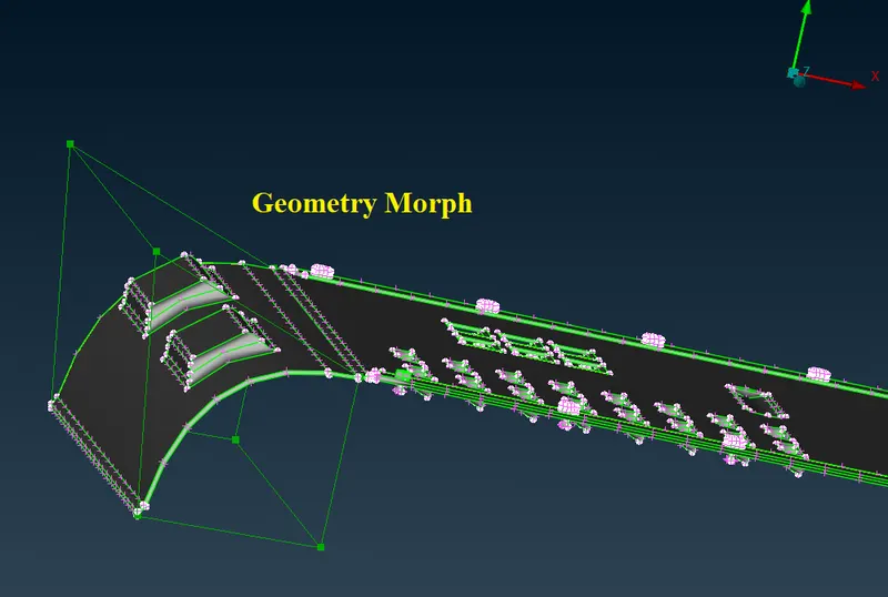
Geometry morphing allows the user to utilize the inventory of all the familiar FE morphing functions to perform equivalent operations in a CAD environment on geometric entities.
Shape of the geometry to be change without doing any changes on the other areas.
Industrial applications of Morphing:
Morphing method capable of changing shape across multiple operating conditions to improve performance or enable new functions to the vehicle or body to which it is attached or comprises.
The Morphing techniques are used in various vehicle manufacturing sector companies to improve passenger coach areas, better aerodynamic design and the efficiency in fuel consumptions for civil and commercial transports etc.
More research activities are bringing morphing to an industrial level.
Aviation industry:
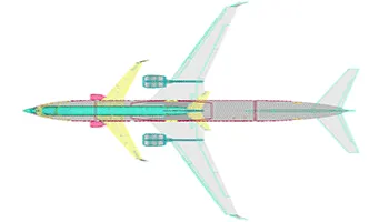
Morphing aircraft are multi-role aircraft that change their external shape substantially to adapt to a changing mission environment during flight.
The use of morphing wings in the aviation industry is predicted to be more fuel-preserving and cost-effective since it increases aerodynamic efficiency and reduces the effort required for the aircraft to reach adequate flying conditions.
The morphing mechanism is to split the airfoil into two airfoils to increase the wing area and, therefore, the lift.
In addition to all of the aforementioned advances, improvements in computational fluid dynamics and optimization have also increased the ability of engineers to improve the designs of aircraft.
The morphing wing is clearly superior to the conventional wing in terms of the lift-to-drag ratio. The morphing wing achieves a maximum lift-to-drag ratio which is larger than that of the conventional wing.
Advantages:
- Offers new perspectives on wing structure design and a new approach to general structural design.
- Potentially flyable solutions aimed at improving the performance of commercial aircraft and UAVs.
Automobile industry:
- In the decades since, cars have just gotten curvier and curvier. The reason for big shift is it turns out it was largely due to three interrelated factors: European style trends, a government-mandated push for fuel economy, and new technologies that allowed manufacturers to more easily design and create curved shapes.
- By Morph method the user has the ability to change physical dimensions and structure appearance depending on the needs.
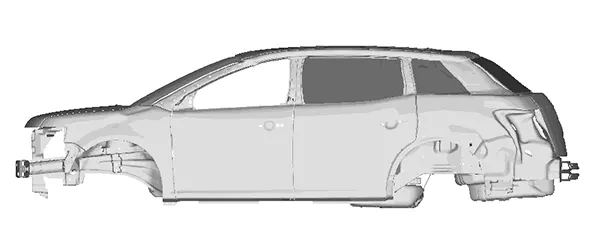
- Its changing shape means it can offer a compact, shorter wheelbase for urban trips, but also extend in length to a limo-like saloon for more comfortable and longer range journeys.
- By Morphing method the Back fender and pillar of SUV frame are streched to change the size as to TUVs variant prototype model.
Advantages:
- Easy visualization of intended variants that the user needs to represent the model.
- By doing directly stretching over the CAD or FE-model The distorting areas can be identified easily.
PHASES:
At each phase it will explain about the process of performing Morphing techniques and increasing the size of parts in the component are to be represented.
Phase-1 Fixing CAD geometry:
Import CAD:
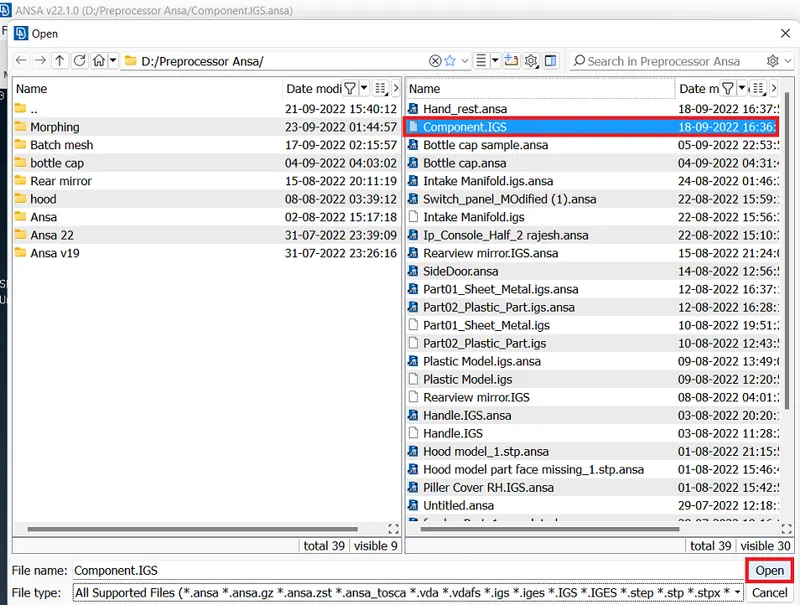
- The given CAD model has to be import in ANSA preprocessor tool by File>open select the file should be in .igs or .stp format and then click open.
Topology Cleanup:
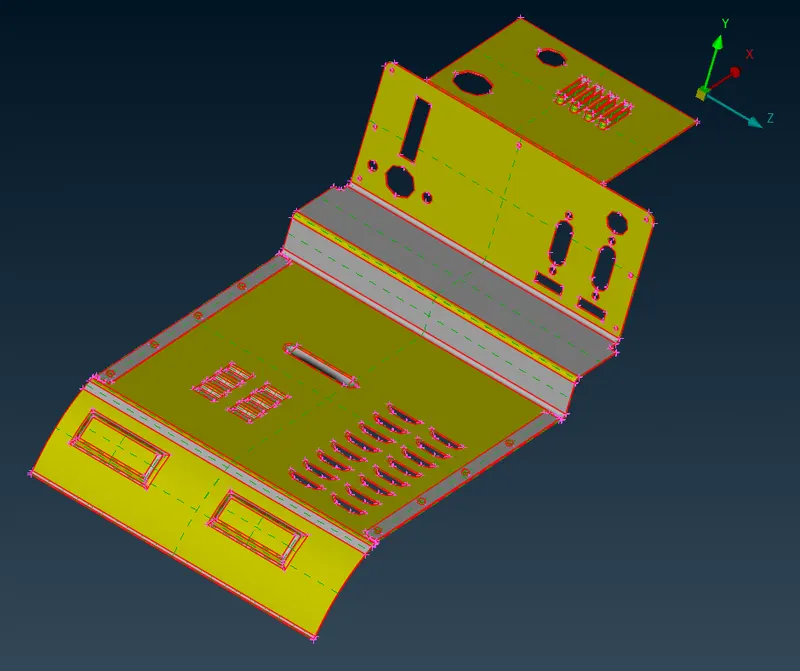
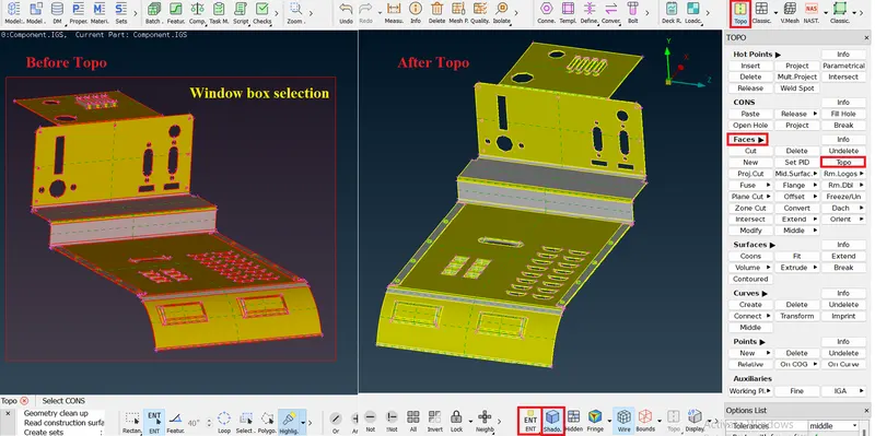
- The Topolgy has to be done if the imported geometry doesn't have the surface connectivity. If all the surfaces are connected perfectly then there is no need to do topology.
- To perform Topology select Faces>Topo in Topo module and select the entire entity then click middle mouse button as confirm.
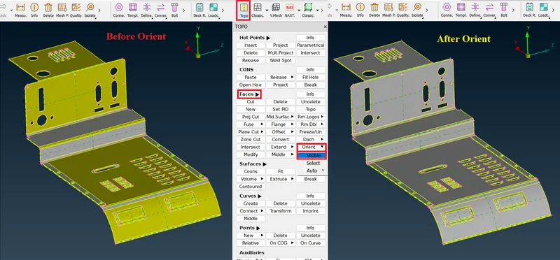
Orientation:
- The orientation to be done to make all the faces of surface to be in one normal direction.
- By selecting Faces>Orient>Visible the component will be Oriented.
Checks geometry:
- The imported model can have geometry errors like unwanted attached cons or gaps between faces or discrepency.
- To solve Checks geometry has processed. In the tools deck select Checks>Geometry then click Execute.
- In Checks manager there is an option called Auto Fix that will fix the error which can be fixed automatically.
- Some of the errors are cannot able to fix automatically by Auto fix method.
- Due to Topo some feature double cons lines having least gap get joined by Topology and formed as Triple con errors.
- Those kind of errors have to be solved manually.
Steps to be followed to solve the errors manually are represented by the below images are,
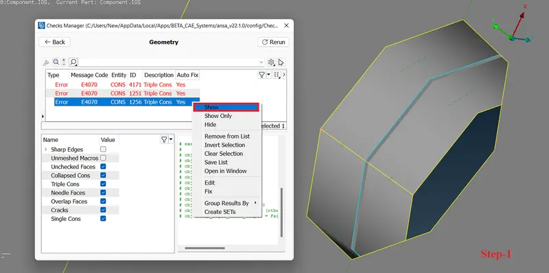
- The Triple cons that are formed by improper Topo of joined least gap Double cons have to be Release.
- To perform Release select Cons>Release>Cons in Topo module and select the Triple con and do confirm.
- The released cons have to be connected properly to obtain a feature gap areas perfectly by performing Topo seperatively on the respective cons by selecting Faces>Topo in Topo module and select the Single con and do confirm.
After resolving all the errors then check the Checks manager gets Executed with no errors.
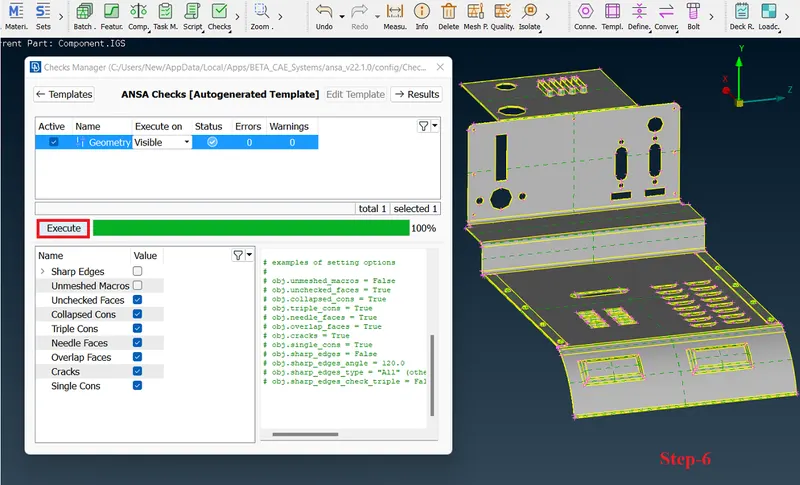
Now the model is ready for performing the Morphing.
Phase-2: Morphing Model-1:
Morphing on Floor panel:
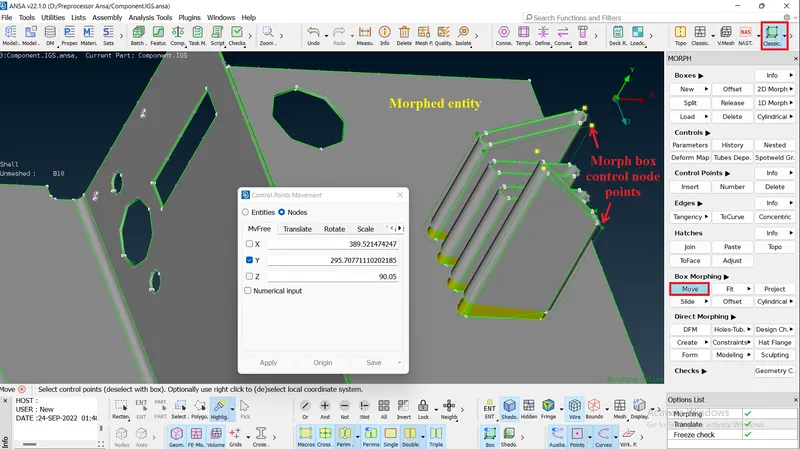
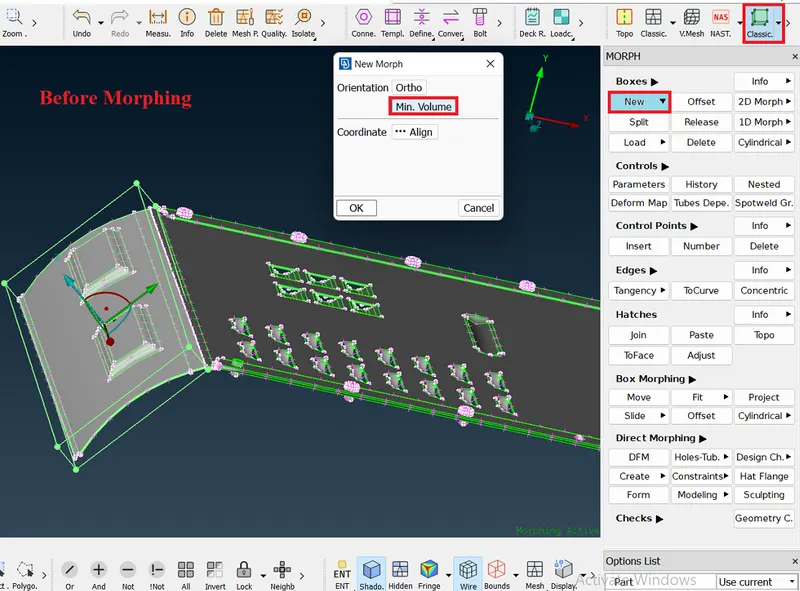
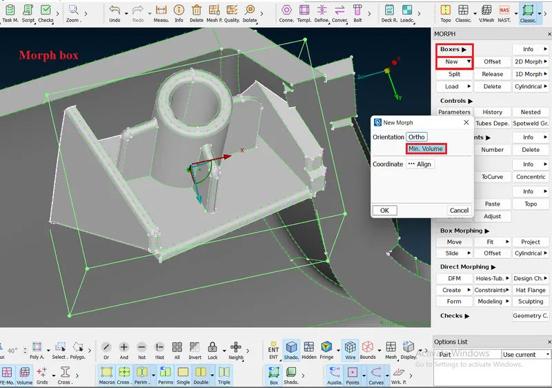
- To perform Morphing the Morph box has to be created by selecting Boxes>New in Classic Morph module over the intended area to morph.
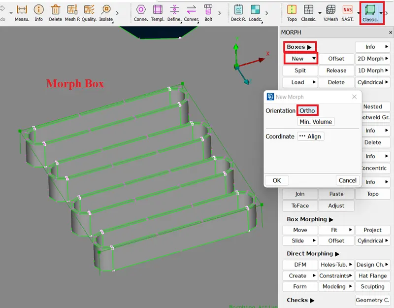
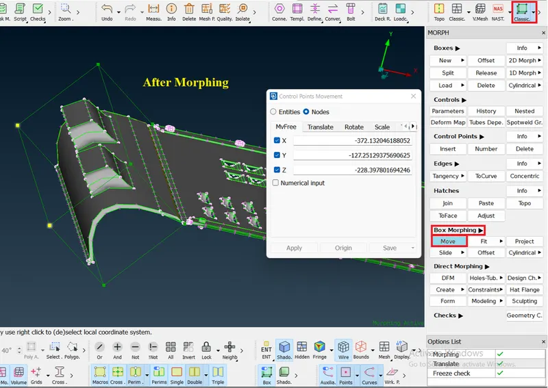
- Then do Morphing select the Box Morphing>Move and select the Morph box control node points then give confirm to Morph it to the required shapes in the component.
Phase-3: Morphing Model-2:
Morphing on Handle Rest:
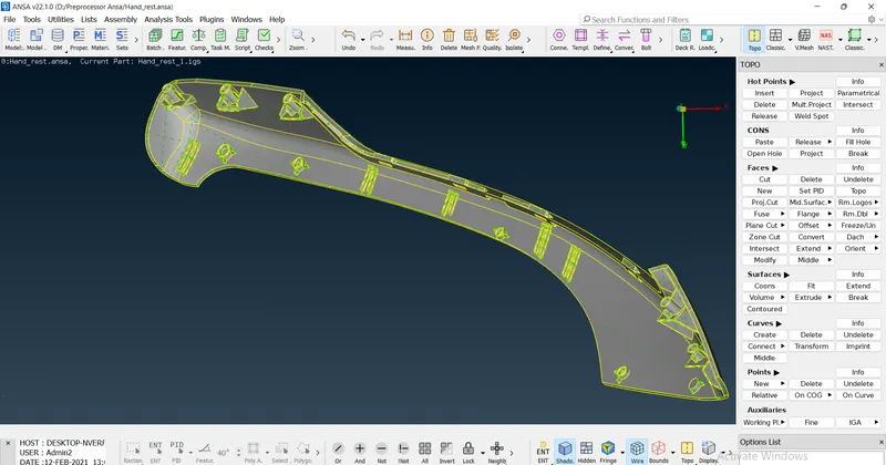
The imported Model-2 Hand Rest component will be,
- The same process of phase-1 has to be performed till the Checks Geometry on the Model-2 Hand Rest component.
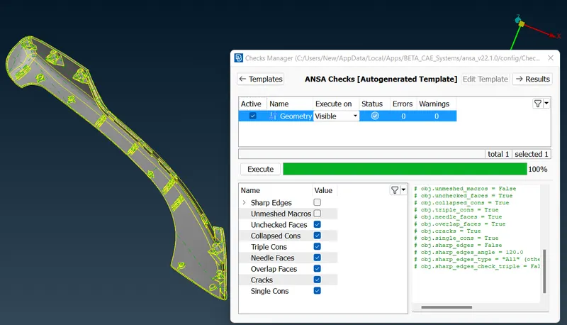
- After performing till Checks Geometry process the model is now ready for Morphing.
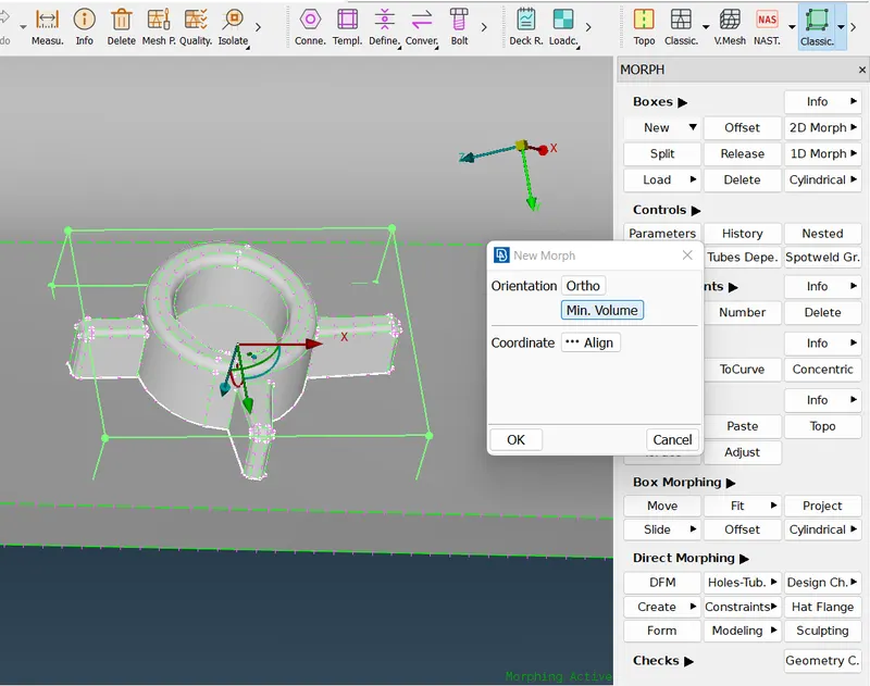
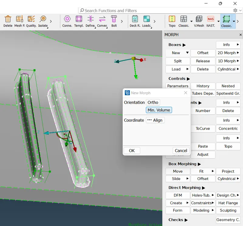
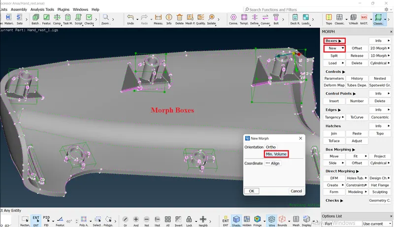
- To do morphing the Morph boxes has to be create using Boxes>New in Classic Morph module, then click Box Morphing>Move to move on required shapes by selecting Boxes control node points to move.
- As same now create Morph boxes on each of Dog houses and Ribs to increase the Height of the Dog houses and Ribs to do morph.
The created Morh boxes are shown in the below images will be,
Before and After images of Morphing will be,
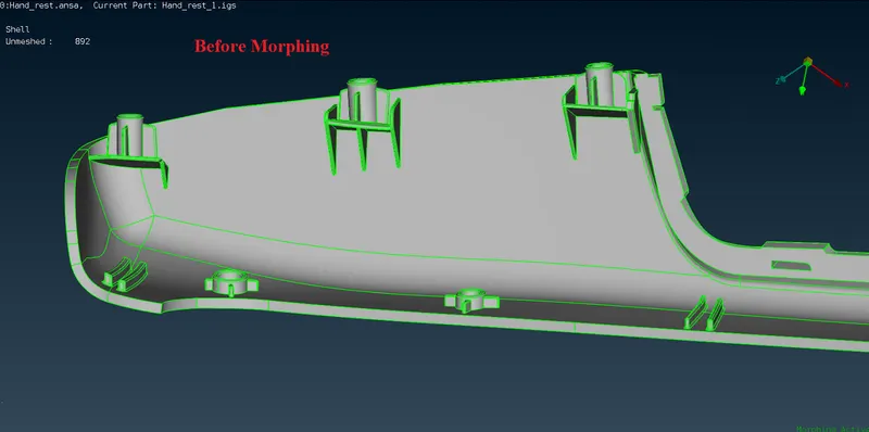
After Morphing the model will will be,
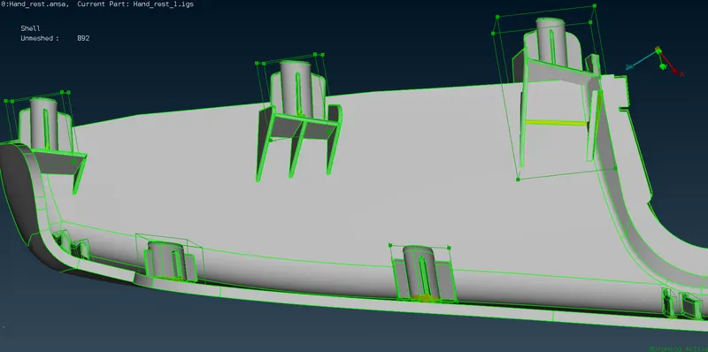
In Morph module select Box Morphing>Move and select the part local areas to perform Morph techniques.
Conclusion:
Morphing techniques are used to performed the Morph on the Model-1 and to increased the height of dog houses and ribs on the given model-2 using the ANSA preprocessor tool.
Learning Outcomes:
- Got some understandings about to perform Morphing and different types of Morphing techniques.
- Learned about the Applications of Morphing in various industries.
Google Drive link:
The folders are uploaded in the google drive and the limk are attached below:
https://drive.google.com/drive/folders/1B-z4a0joU8476ZCm6x2rA2L0hzkYByow?usp=sharing