Week 6 - CHT Analysis on a Graphics card
Aim:
- To Perform a steady-state conjugate heat transfer analysis on a model of a graphics card.
- To Run the simulation by varying the velocity from 1m/sec to 5m/sec for at least 3 velocities and discuss the results.
- To Find out the maximum temperature and heat transfer coefficient attained by the processor.
- To Prove that the simulation has achieved convergence with appropriate images and plots.
- To Identify potential hotspots on the model.
Introduction:
A graphics card (also called a video card, display card, graphics adapter, VGA card/VGA, video adapter, display adapter, or mistakenly GPU) is an expansion card which generates a feed of output images to a display device, such as a computer monitor. Graphics cards are sometimes called discrete or dedicated graphics cards to emphasize their distinction to integrated graphics. A graphics processing unit that performs the necessary computations is the main component of a graphics card, but the acronym "GPU" is sometimes also used to refer to the graphics card as a whole.Usually, a graphics card comes in the form of a printed circuit board (expansion board) which are to be inserted into an expansion slot.[5] Others may have dedicated enclosures, and they are connected to the computer via a docking station or a cable. These are known as external GPUs (eGPUs). Graphics cards are often preferred over integrated graphics for increased performance.
Procedure:
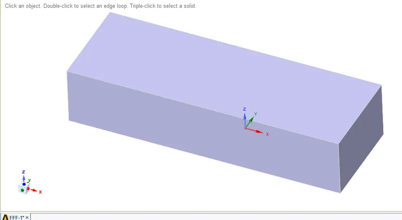
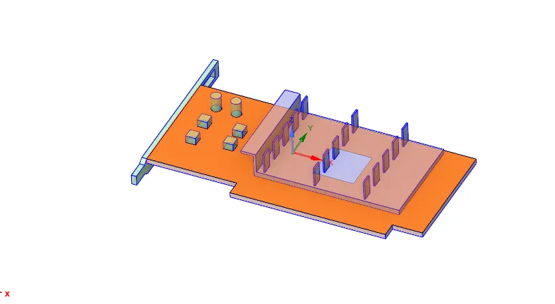
step 1: import the geometry into space claim and perform perform share topology operation between the surfaces that the information could be shared between the different components of the graphics card.
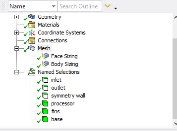
step 2: open mesh and create name selections for the surfaces for defining the boundary conditions and cell zones during setup.
step 3: after that create a base mesh is generated with element size=10mm. This mesh helps us to understand the initial solution which in order to determine the location where mesh refinement is required and the sizing is done for graphices card with element size = for better understanding of results in the setup(fluent).
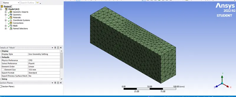
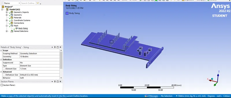
for case 2 the mesh is refined further to obtain better results with element size = 3mm and body sizing for graphics card = 0.9mm and face sizing for fin=0.3mm.
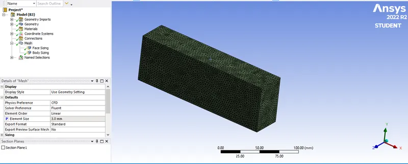
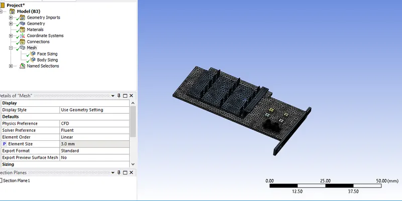
step 3: open setup in ansys workbench and follow the below procedures for all the cases.
-
- under general->select steady->pressure based->absolute velocity.
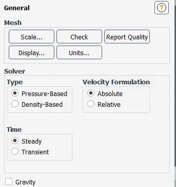
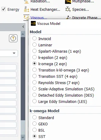
- viscous model->k-omega SST model and enable energy as we are dealing thermal heat transfer.
-
- under material->Different materials are used for each part, some of which are created newly, they are
fins :Aluminium
-
base(PCB) : FR-4
- processor : Silicon
- enclosure : Air
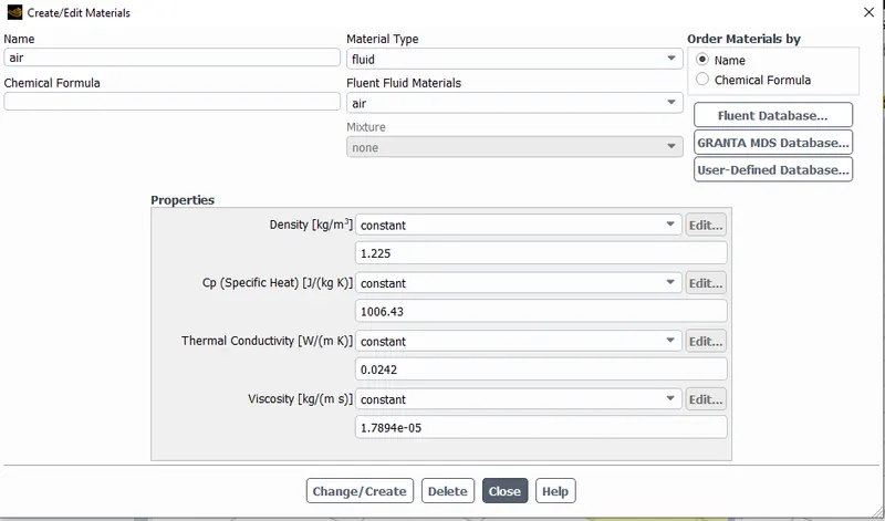
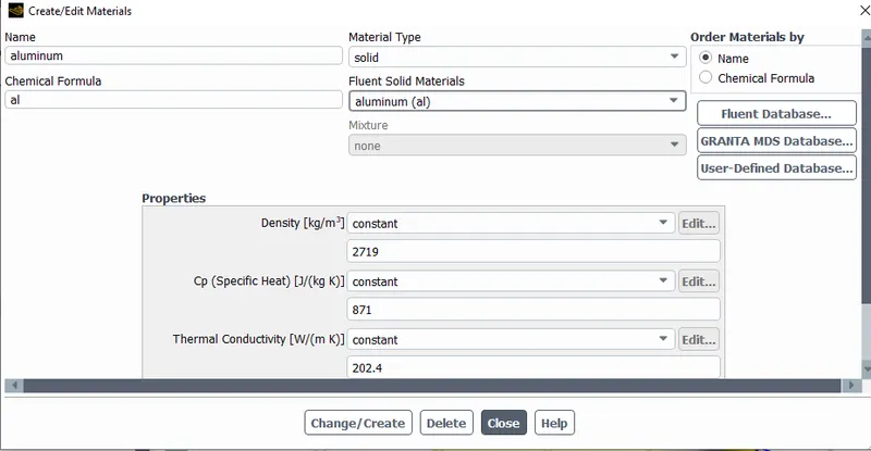
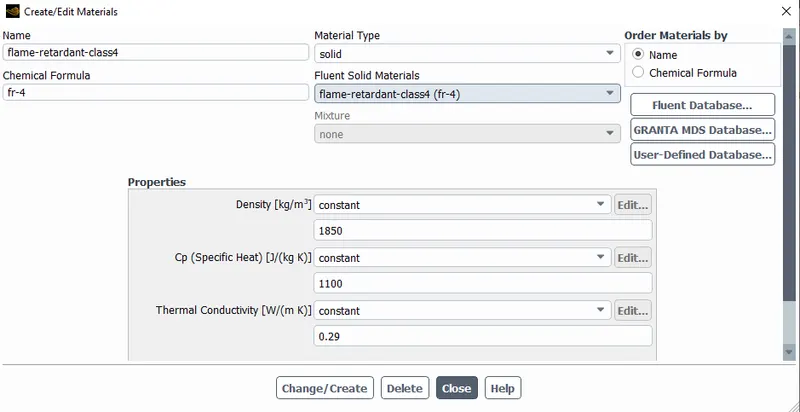
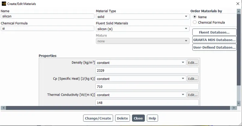
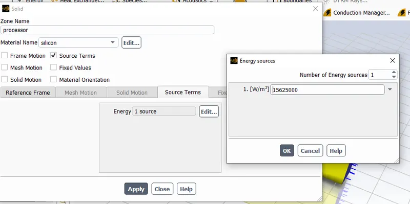
- under Zone assign the materials created to necessary components as shown in the below snaps and for processor enable source, since the processor is assumed as the only source of heat. The heat generated by the processor
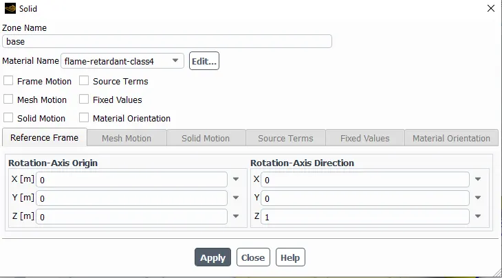
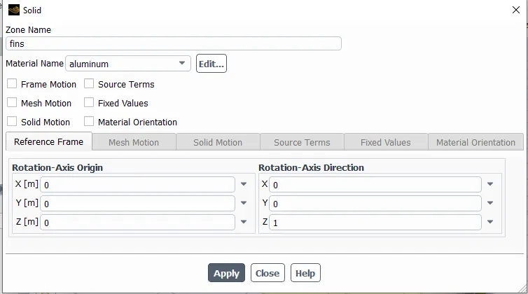
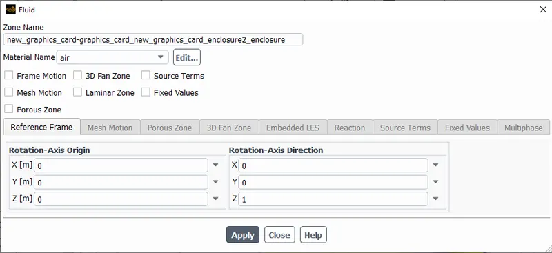
for the processor the heat dissipation rate is calculated using the below formula
Q= P/V in W/m^3
where Q=Heat Generated
P=Graphics Card Power = 1W(assume)
V=Volume of the card = 8mm x 8mm x 1mm(Through spaceclaim)
∴ Q=15625000W/m^3.
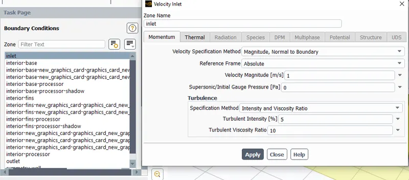
- Under boundary conditions give the inputs as mentioned in the below.
Boundaries->Inlet->Type: Velocity-Inlet=1m/s->Temperature: 300 K
Boundaries->Outlet->Type: Pressure Outlet->Pressure: 0 Pa(Gauge Pressure)
Symmetry: Symmetry
Wall: Wall
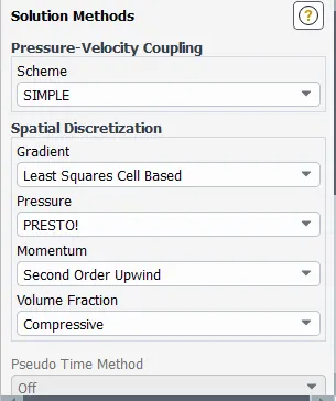
- choose the method as simple
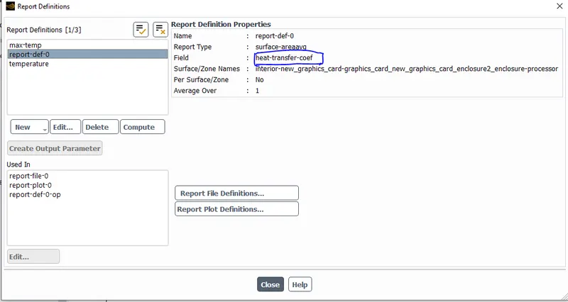
- Intialize the solution by using hybrid initialization adn create contours for temperature and velocities and create reports for Maximum temperature, surface heat transfer coefficient.
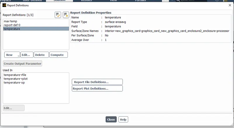
- Run for 200 iterations and observe the residuals and other reports.
Results:
case 1:
Base mesh
No of elements=165571
No of nodes=28951
inlet velocity= 1m/s at 300k
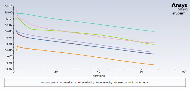
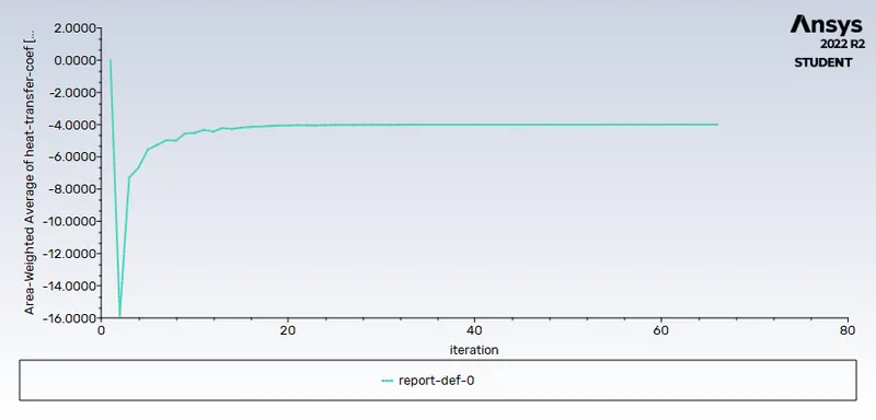
Residuals Area weight avg of heat transfer coefficient=-3.9966
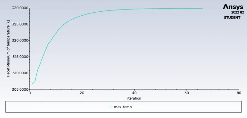
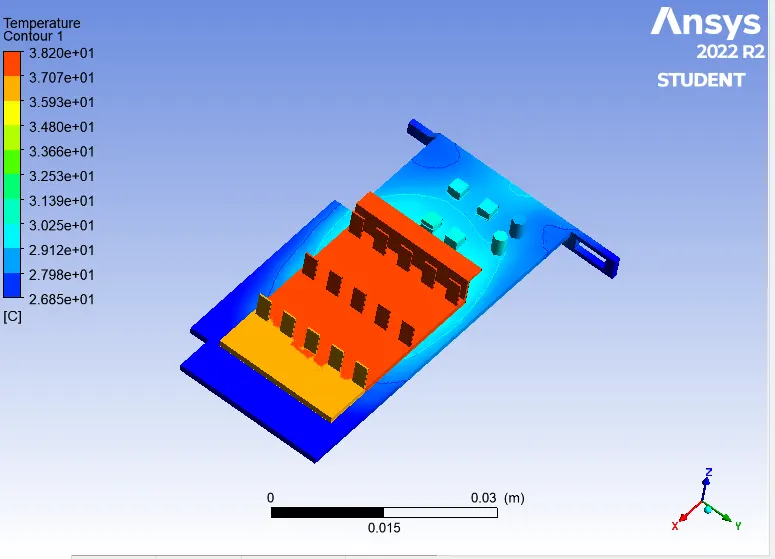
Maximum temperature=330.9577K global hotspot region
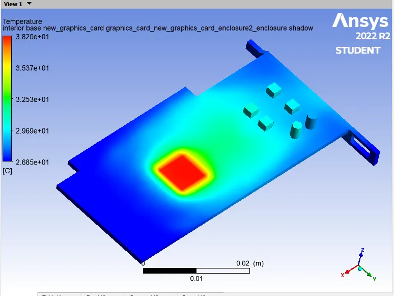
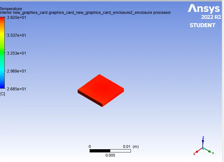
Potential hotspots at base Potential hotspots at processor
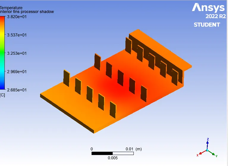
Potential hotspots at fins
Case 2:
Refined mesh
No of elements=396631
No of nodes=78784
inlet velocity= 1m/s at 300k
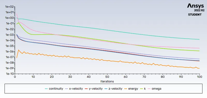
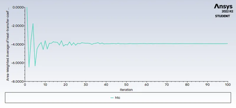
Residuals Area weight avg of heat transfer coefficient=-3.9378
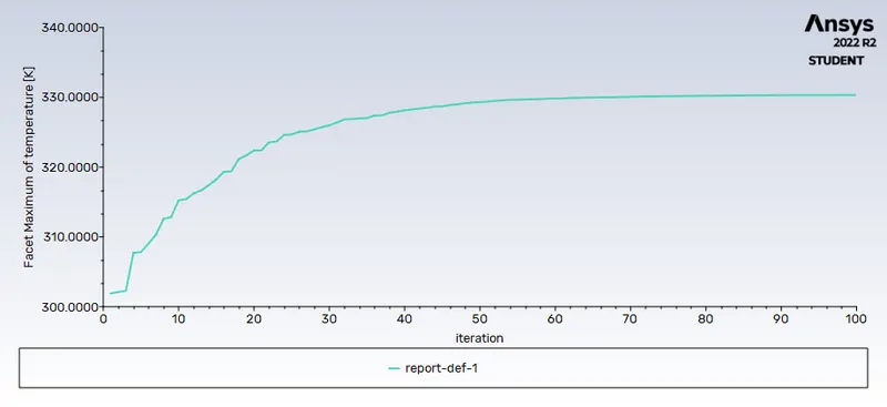
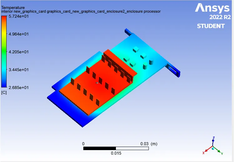
Maximum temperature=330.2K global hotspot region
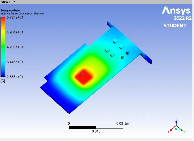
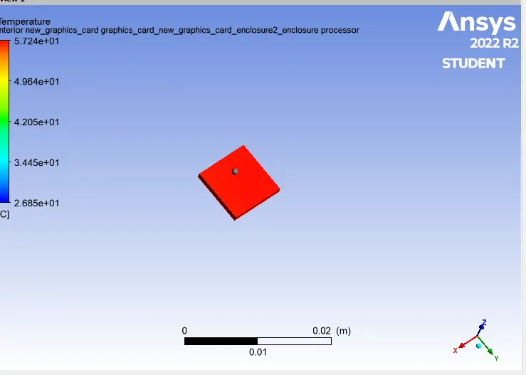
Potential hotspots at base Potential hotspots at processor
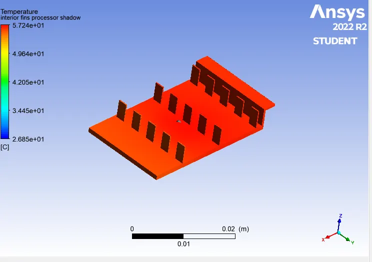
Potential hotspots at fins
Since there is no much of difference between temperatures and surface heat transfer coefficient for the two cases we proceed with any of the cases for conducting the simluation for the velocities 3m/s & 5m/s.
here were are going to use case refined mesh for solving for other velocities.
case2(a): For velocity =3m/s mesh element size and nodes as per case 2 refined mesh
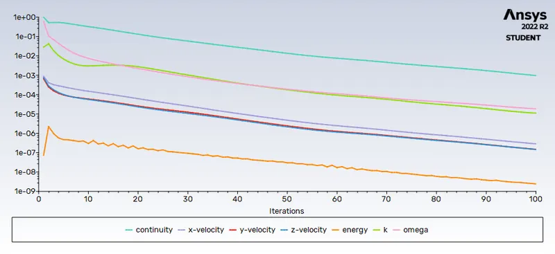
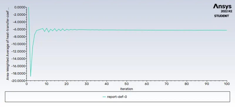
Residuals Area weight avg of heat transfer coefficient=--6.2668452
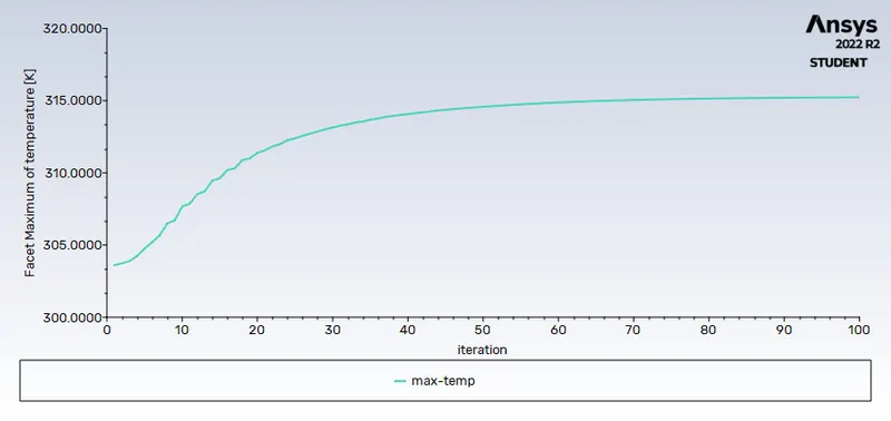
Maximum temperature=314.34867K global hotspot region
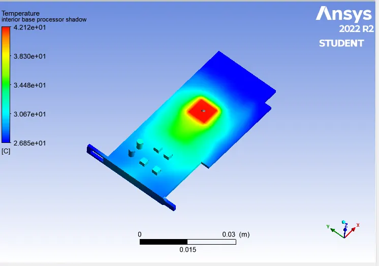
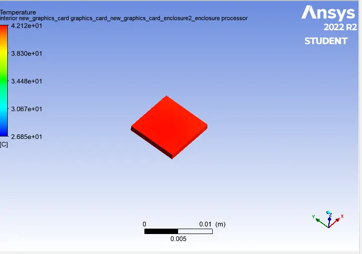
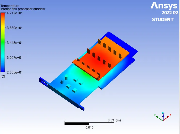
Potential hotspots at base Potential hotspots at processor
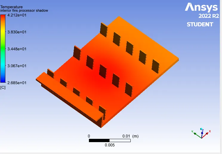
Potential hotspots at fins
case2(b): For velocity =5m/s mesh element size and nodes as per case 2 refined mesh
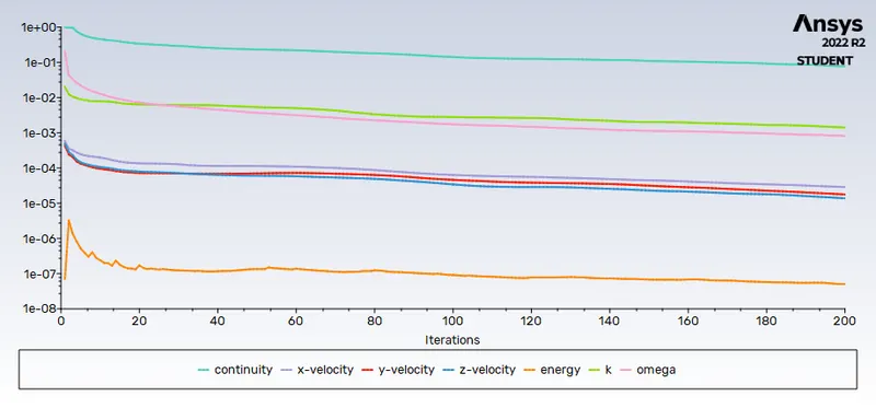
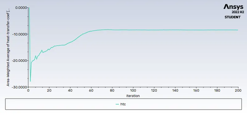
Residuals Area weight avg of heat transfer coefficient=-8.4392531
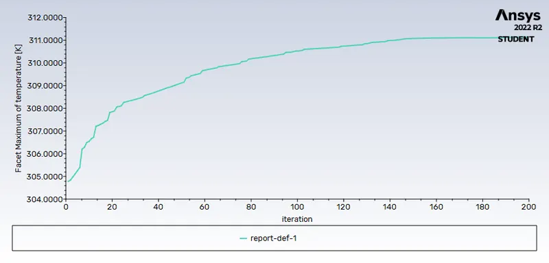
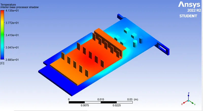
Maximum temperature=311.1139K global hotspot region
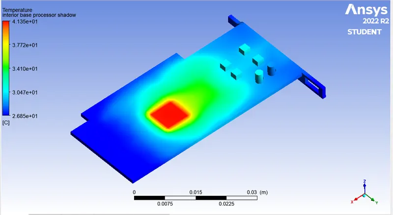
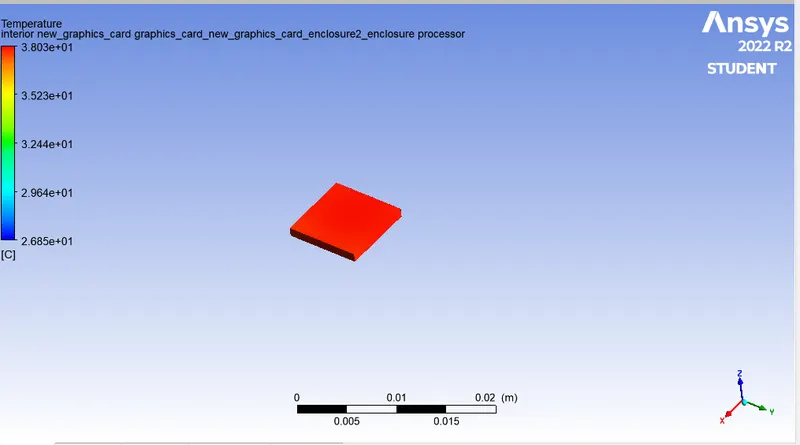
Potential hotspots at base Potential hotspots at processor
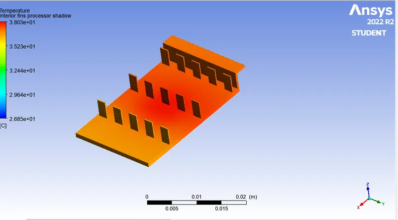
Potential hotspots at fins
| Parameters |
base mesh at 1m/s |
refined mesh at 1m/s |
refined mesh at 3m/s |
refined mesh at 5m/s |
| maximum temperature(K) | 330.95 | 330.2 | 314.34 | 311.11 |
| surface heat transfer coefficient(W/m^2 K) | -3.9966 | -3.9378 | -6.2668 | -8.4392 |
A converged solution was obtained for the given input, which was observed and analyzed by above residuals and plots and also we identified the potential hotspots regoin at the graphics card/
As velocity increases, we saw a decrease in temperature and rise in surface heat transfer coefficient which shows that the higher heat dissipation rate can be achieved from higher velocites at the graphics card.
From the temperature distribution across the graphics card we can see that potential hotspots near the processor which is in thermal contact with base(PCB) & fins. Based on the thermal conductivity of the material this temperature is distributed accordingly.
refining of mesh is done for fins, base and processor of the graphic card in order to calculate the wall heat transfer coefficient.
Conclusion:
- Performed a steady-state conjugate heat transfer analysis on a model of a graphics card.
- we ran the simulation by varying the velocity from 1m/sec to 5m/sec for at least 3 velocities at different mesh cases.
- the maximum temperature and heat transfer coefficient attained by the processor was calculated and studied.
- we Proved that the simulation has achieved convergence with appropriate images and plots.
- potential hotspots on the model were identified and analyzed.