Week 2 Challenge : Surface meshing on a Pressure valve
Aim:For the given model, check for the geometrical errors and perform Topology cleanup and mesh for three different cases.
Introduction: A pressure valve is a type of safety valve used to control or limit the pressure in a system,basically it was designed to control or relieve overpressure levels for optimal functionality in any system in many industries. in this week challenge we are going to perform topology cleanup, PID creation and assignment of the given model using different selection techniques and visibility tools and mesh the model for three different cases.
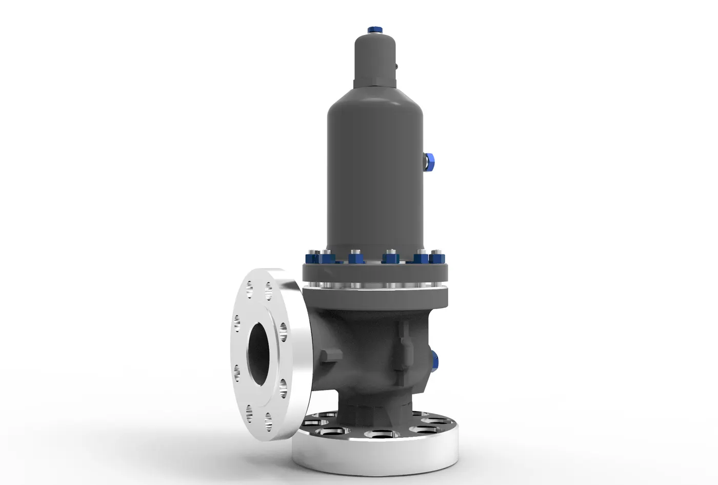
Procedure:
step 1: Import the geometry
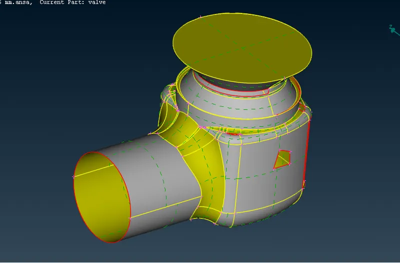
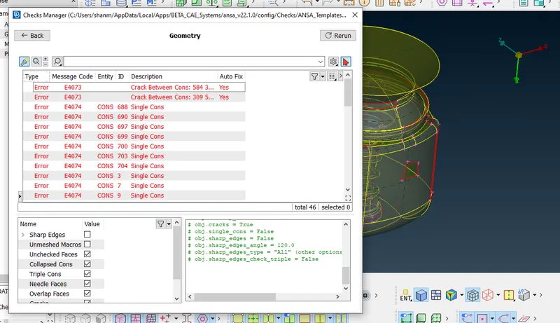
step 2: Analyze the single and double cone under check-geometry-all the required options-execute
step 3: begin the solve all the singe cone(open surfaces) using Face command under which click the new and use the requied operation suitable.
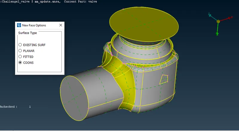
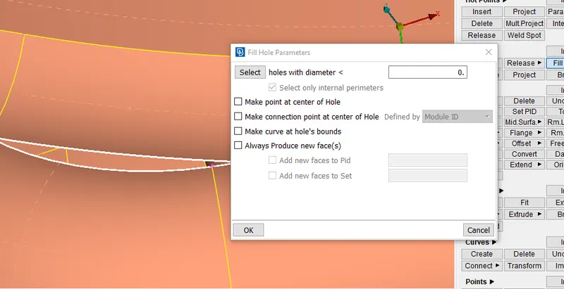
step 4: fill hole option can be also used to create surface on the circular or any enclosed surface.
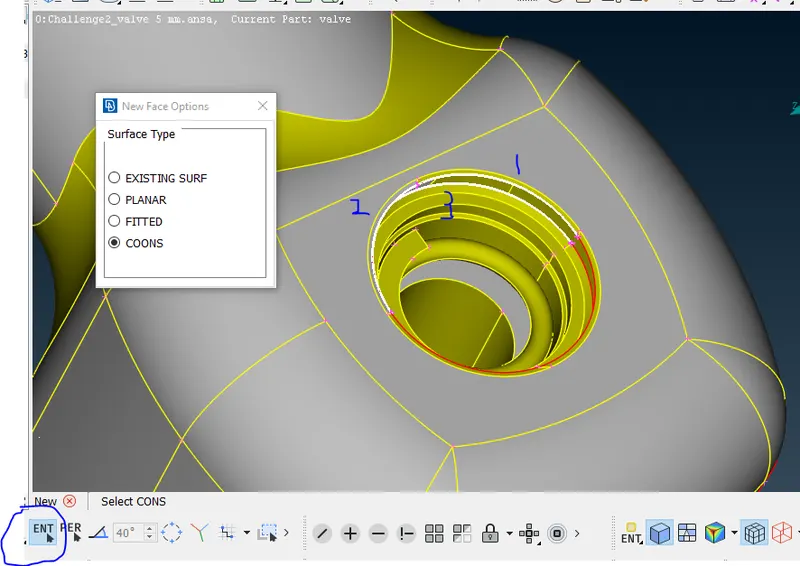
step 5: the last part for solving the single cone is little tricky, so we need to need to select individual suface to obtain the vertical surface since cones are in uneven length.
step 6: Analyzing the triple contacted surface using !- command to understand the triple cone.
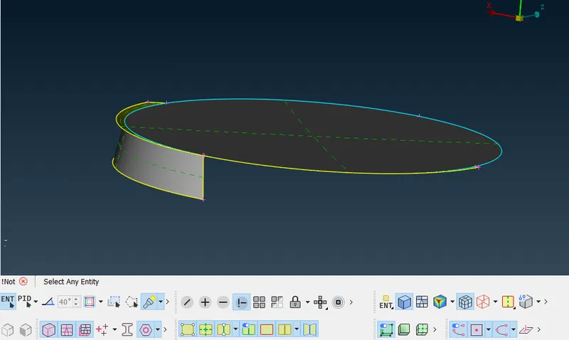
step 7: visibilty tool such as single(red line), double(yellow line), triple(blue line) cone icon to be selected in order to indentify in the model and we can use wire frame option in order to clearly analyze different cones using ctrl+shift
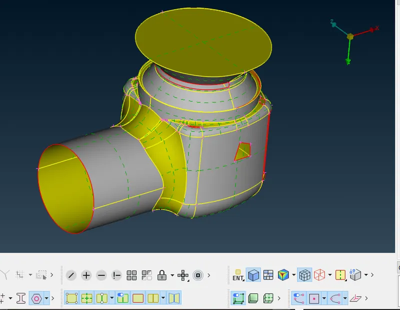
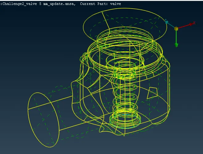
step 8:after cleaning all the single cones, triple cone(blue line) to be provided to the open surface of the valve.
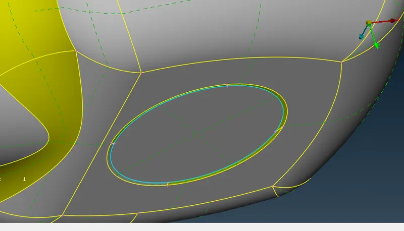
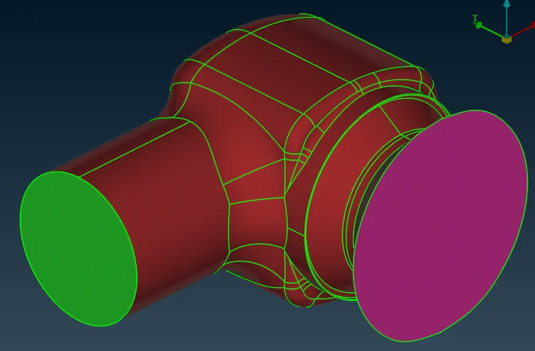
step 9: creating PID to different parts by enabling PID icon and also in property manager.
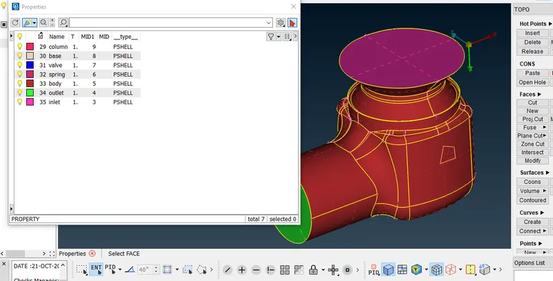
step 10: Assigning the PID can be done by right click on the PID-apply-select the required component-middle click.
basically the properties assigned to the surface can be seen in solid model using different visibility tools.
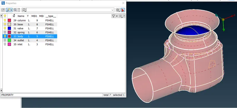
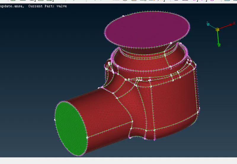
step 11: creating mesh with 3 different target length with tria mesh which should be given in parameter, macros, mesh parameters and qualty criteria and then we need to give spot mesh to different component.
case 1: mesh target length =1mm
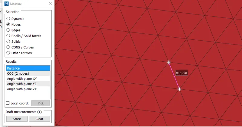
case 2: mesh length = 3mm.
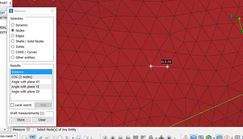
case 3: mesh target length =5mm
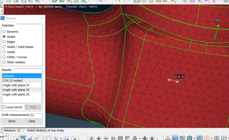
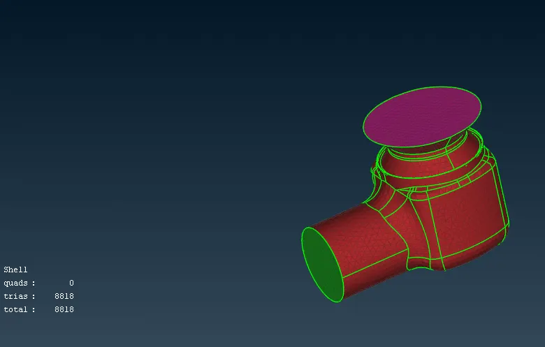
step 12: Analyze the mesh pattern and check all the surface are meshed or not.
Learning outcome:
1. to understand how to do topology cleanup using various tools and solve erros which occurs during checking the geometry.
2. To learn and create PID and assigning those PID to differnent components.
3.With the help of created PID meshing can be for different parameters and target lengths as given.
4. understanding the meshing processes and which yields best results for the given target lengths.
Results:
From the above procedures and attached ANSA file we can clearly see that 1mm mesh length yields best results without much the afftecting the geometry of the model. since for the cases of 3mm and 5 mm we can clearly see that meshing at smaller size component(spring) afftect the structure of the geometry and more in case of 5mm for spring and valve head.