Week 2 - Flow over a Cylinder.
Aim:
- Simulate the flow over a cylinder and explain the phenomenon of Karman vortex street.
- Simulate the flow with the steady and unsteady case and calculate the Strouhal Number for Re= 100.
- Calculate the coefficient of drag and lift over a cylinder by setting the Reynolds number to 10,100,1000,10000 & 100000. (Run with steady solver)
- To Discuss the effect of Reynolds number on the coefficient of drag.
- Plot the coefficient of drag and lift.
- Plots vortex shedding behind the cylinder.
Introduction:Flow over a cylinder has been studied extensively, bothexperimentally and numerically, for several decades.The simplicity of the geometry and the abundance of interesting flow features continue to make this flow subject of many current studies. The flow over a cylinder exhibits vastly different behaviors as the Reynolds number, based on the free-stream velocity, cylinder diameter, and kinematic viscosity, increases from zero to large values. Steady laminar flow exists at Reynolds numbers up to approximately Re ≈40 with a pair of
symmetric counter-rotating vortices forming behind the cylinder at Re≈5. The laminar vortex shedding, also known as the Karman vortex street, is observed at Reynolds numbers
up to about Re≈190.Examples are flow separation, the primary instability with development of the unsteady von Ka´rma´n vortex street, transition to three-dimensionality with interaction of ‘mode A’ and ‘mode B’ instabilities, the occurrence of turbulence in the wake, and the Kelvin–Helmholtz instability of the separated shear layer. The cylinder flow has been investigated for more than one century, starting with fundamental work of Strouhal (1878) on the dependency between frequency of vortex shedding, free-stream velocity, and cylinder diameter.
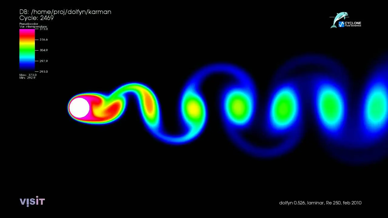
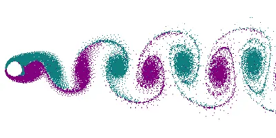
Karman vortex street:a Kármán vortex street is a repeating pattern of swirling vortices, caused by a process known as vortex shedding, which is responsible for the unsteady separation of flow of a fluid around blunt bodies.
Reynolds number: The Reynolds number (Re) helps predict flow patterns in different fluid flow situations by measuring the ratio between inertial and viscous forces. At low Reynolds numbers, flows tend to be dominated by laminar (sheet-like) flow, while at high Reynolds numbers flows tend to be turbulent. The turbulence results from differences in the fluid's speed and direction, which may sometimes intersect or even move counter to the overall direction of the flow (eddy currents). These eddy currents begin to churn the flow, using up energy in the process, which for liquids increases the chances of cavitation. Reynolds numbers are an important dimensionless quantity in fluid mechanics.
Re = rho*V*d/Dynamic Viscosity
i) Procedures:
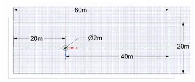
step 1: open ansys workbench and create a geometry as per below dimensions in space claim
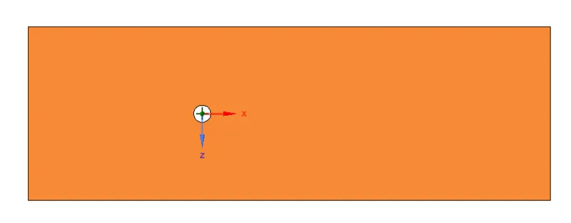
since analysis is conducted for a flow over a cylinder delete the surface accross the cylinder
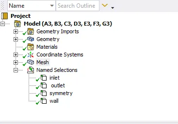
step 2: open mesh and start with default meshing the geometry and create name selections for all the edges and 2D circle.
since default element is coarse and quadrilateral, we can insert a method with triangle and generate the mesh
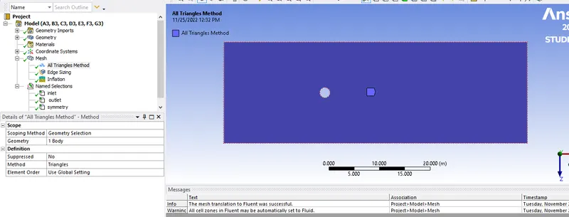
step 3: change the element size to 0.25m and we can see that size of circle looks disoriented, so we can an edge sizing of the circle egde and input the no of divisions to 36.
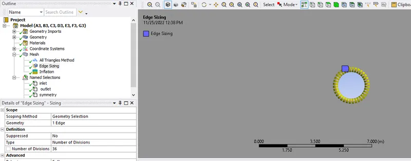
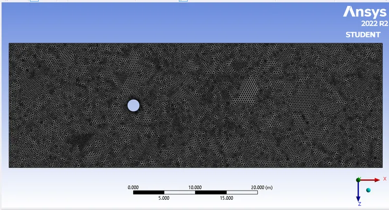
step 4: Create an inflation layer near the cylinder wall in order to obtained better results, go to mesh -> inflation -> select the body and edge -> inflation option = 1st layer thickness ->1 st layer height =5e-3 m ->maximum layer=6.
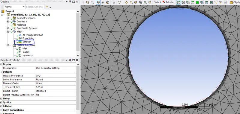
step 5: After meshing, go to workbench and right click on setup->update->double click on setup to open the fluent
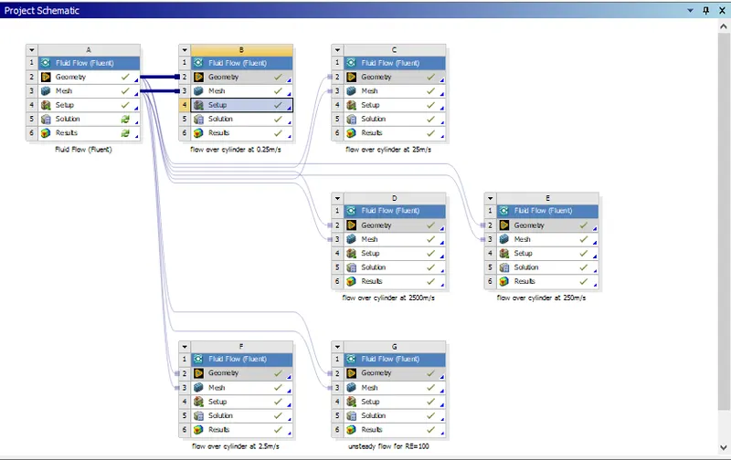
step 6:We need to Calculate the coefficient of drag and lift over a cylinder by setting the Reynolds number to 10,100,1000,10000 & 100000. so we will create solutions for each cases,
before that we need to understand the definitions of coefficient of drag & lift, monitor points and vortex shedding.
coefficient of drag: the drag coefficient(Cd)">(Cd) is a dimensionless quantity that is used to quantify the drag or resistance of an object in a fluid environment, such as air or water.

c_d = drag coefficient
F_d = drag force
rho = mass density of the fluid
u = flow speed of the object relative to the fluid
A = reference area
coefficient of lift:the lift coefficient (CL) is a dimensionless quantity that relates the lift generated by a lifting body to the fluid density around the body, the fluid velocity and an associated reference area.

where L, is the lift force, S is the relevant surface area and q is the fluid dynamic pressure, in turn linked to the fluid density rho and to the flow speed u.
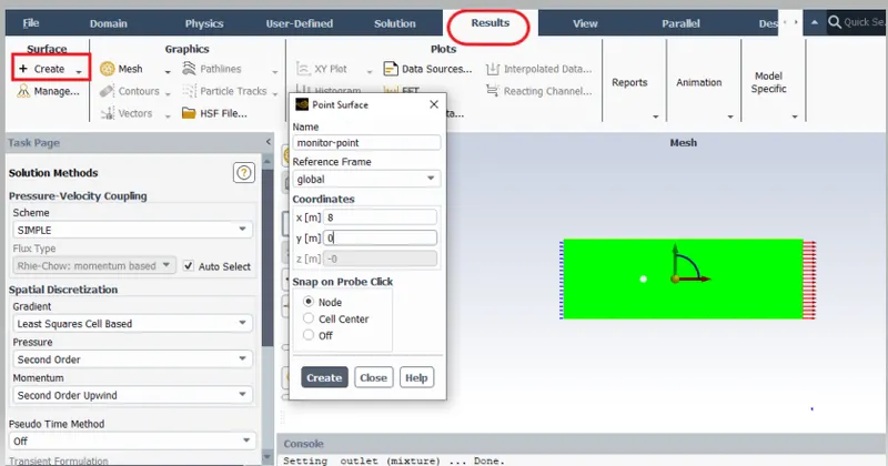
Monitor points: It is a point which is used to set up tools for monitoring the convergence of the solution dynamically by checking residuals, statistics, force values, coefficient of drag & lift.
vortex shedding:vortex shedding is an oscillating flow that takes place when a fluid such as air or water flows past a bluff (as opposed to streamlined) body at certain velocities, depending on the size and shape of the body. In this flow, vortices are created at the back of the body and detach periodically from either side of the body forming a Kármán vortex street. The fluid flow past the object creates alternating low-pressure vortices on the downstream side of the object. The object will tend to move toward the low-pressure zone.
For Reynolds number from 10,100,1000,10000 & 100000 the below following common conditions are used except inlet fluid velocity they are:
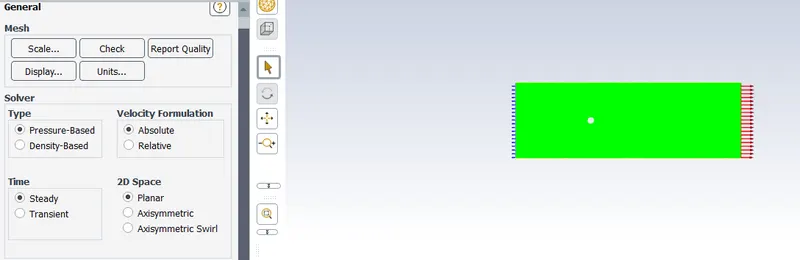
check the mesh
- under physics->general change to steady state
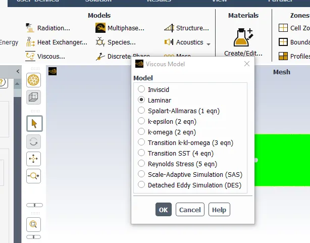
- physics->viscous->laminar
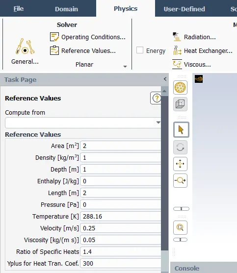
- physics->reference values
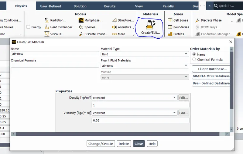
- click on material->fluent database->click on air as fluid->click on copy-> update the name as per our choice->close->click on change/create->exit, now click cell zones under zones, under fff_surface-> click on edit->change the fluid to air-new->close, Again go back to material->delete all fluid materails other than the created one->update the denisty to 1 Kg/m^3,dynamic viscosity to 0.05 Kg/m s->click change/create->close
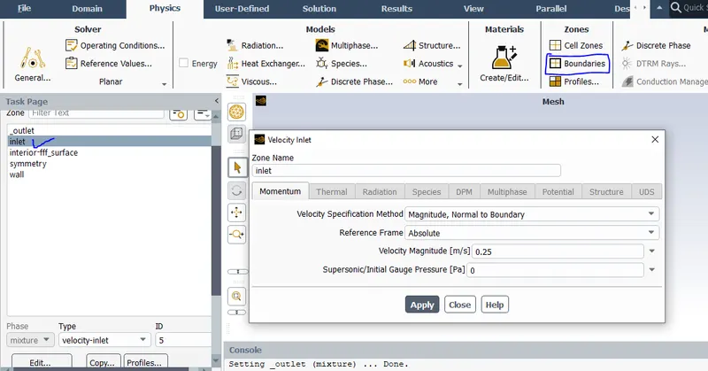
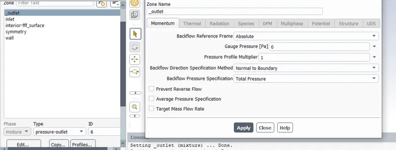
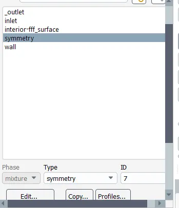
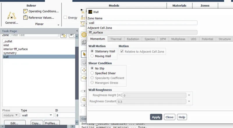
- Boundary conditions->inlet = fluid velocity;outlet=gauge pressure'0';symmetry remains as it is->wall= with no slip conditions
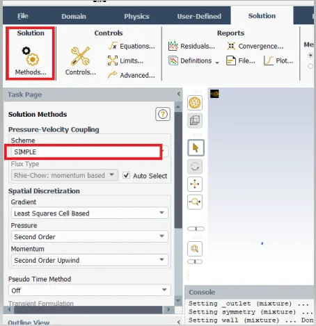
- under solutions->method->change the scheme to simple.
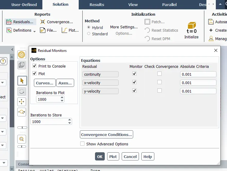
- solutions->residuals->uncheck all the convergence criteria as we need to run the calculation till the end of iterations.
- under results->create->point->coordinate-x=8m,coordinate-y=0m->create
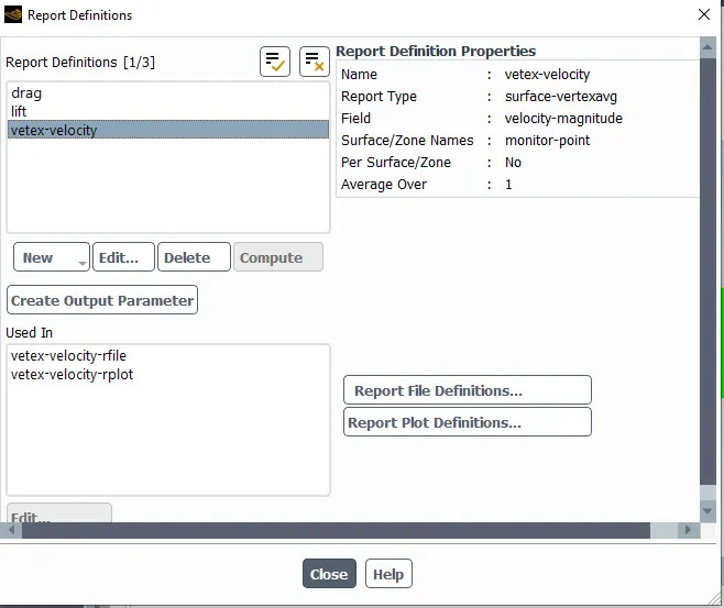
- under solutions for report_1->definitions->new->surface report->vertex average->select the zones as monitor-point,report_2->definitions->new->force report->generate the report for lift and drag.
- peroform hybrid initialization
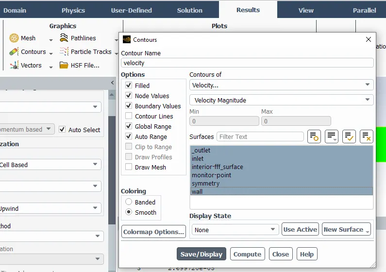
- under results->contours->create contours for velocity & pressure.->save/display.
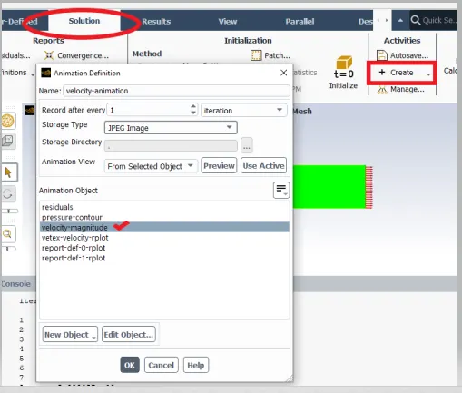
- create animations for the velocity for better visualization and understanding.
- Run the calculation for 350 iterations and click calculate
- Analyze all the plot report and note down the values of coefficient of drag & lift.
step 7: Following the step 6 procedure for all the cases of reynolds number under steady state
step 8: calculate the strouhal number at Re =100 for both steady & unsteady flow
Results:
For reynolds number Re=10
∴ fluid velocity=0.25m/s(calulated using reynolds number formula)
dynamic viscosity=0.05 kg/m s
fluid meduim= air-new
fluid density=1kg/m^3
Plots for Re=10
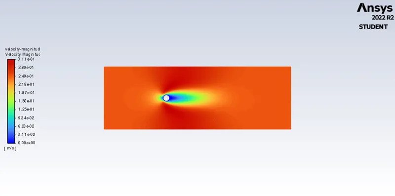
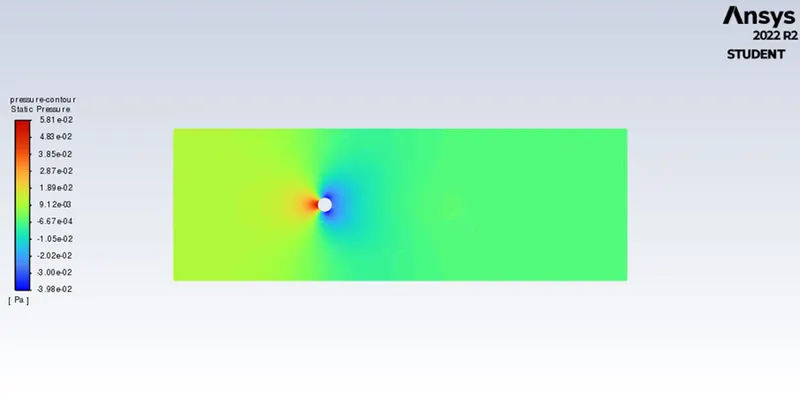
Velocity contour Pressure contour
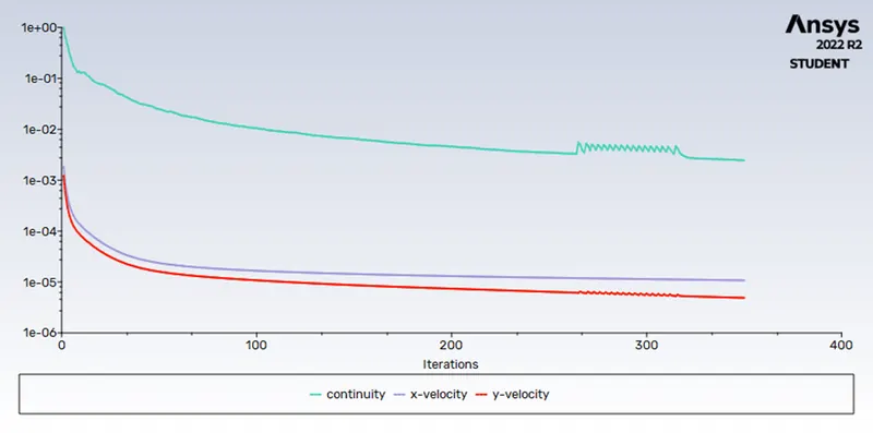
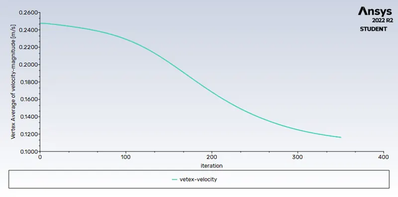
Residuals vertex average velocity
coefficient of drag coefficient of lift
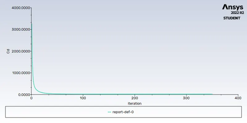
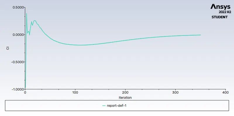
For reynolds number Re=100
∴ fluid velocity=2.5m/s(calulated using reynolds number formula)
dynamic viscosity=0.05 kg/m s
fluid meduim= air-new
fluid density=1kg/m^3
Plots for Re=100
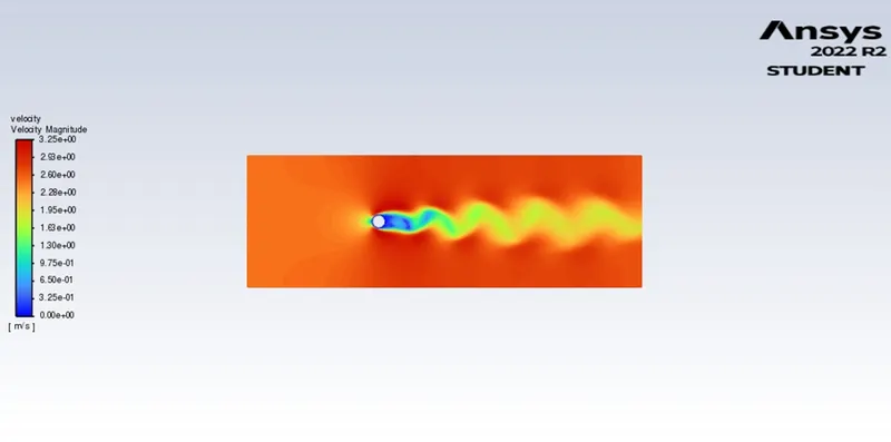
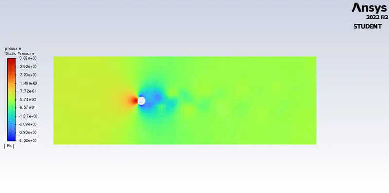
Velocity contour Pressure contour
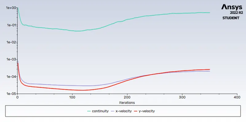
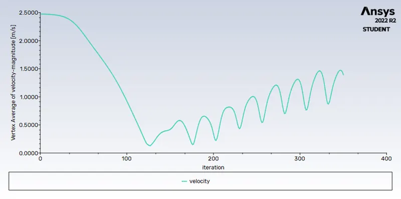
Residuals vertex average velocity
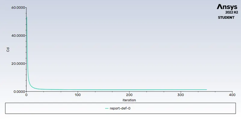
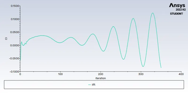
coefficient of drag coefficient of lift
For reynolds number Re=1000
∴ fluid velocity=25m/s(calulated using reynolds number formula)
dynamic viscosity=0.05 kg/m s
fluid meduim= air-new
fluid density=1kg/m^3
Plots for Re=1000
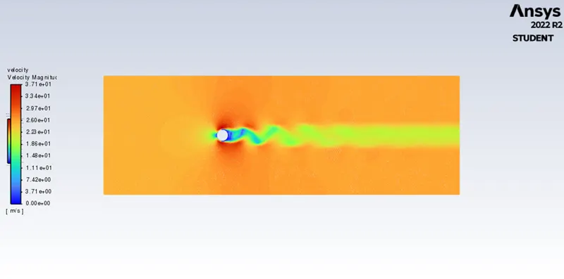
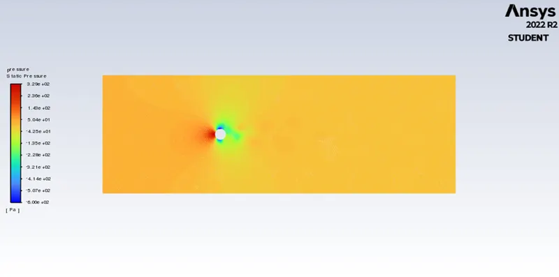
Velocity contour Pressure contour
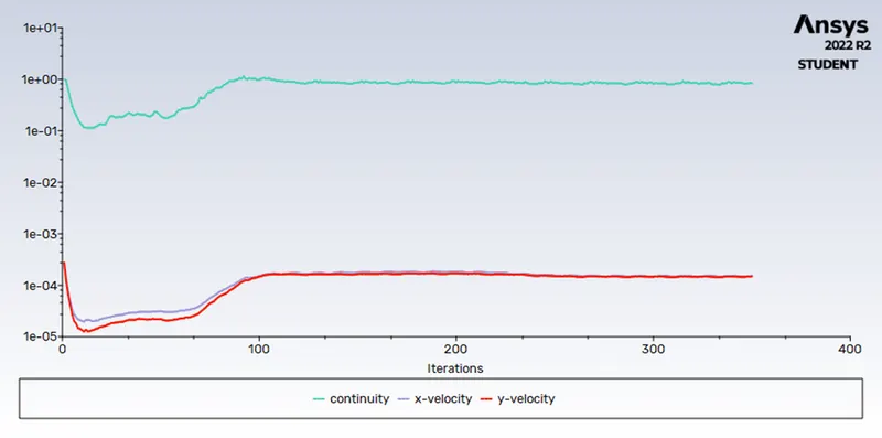
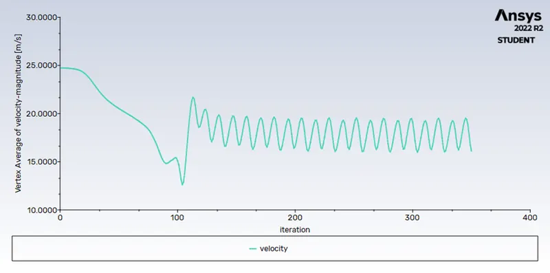
Residuals vertex average velocity
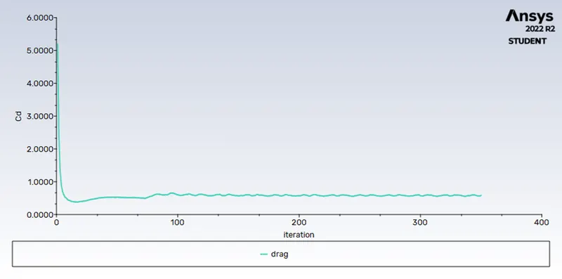
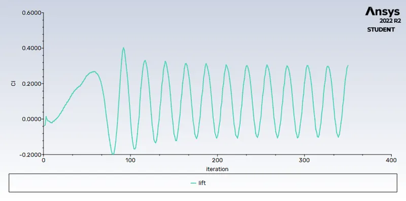
coefficient of drag coefficient of lift
For reynolds number Re=10000
∴ fluid velocity=250m/s(calulated using reynolds number formula)
dynamic viscosity=0.05 kg/m s
fluid meduim= air-new
fluid density=1kg/m^3
Plots for Re=10000
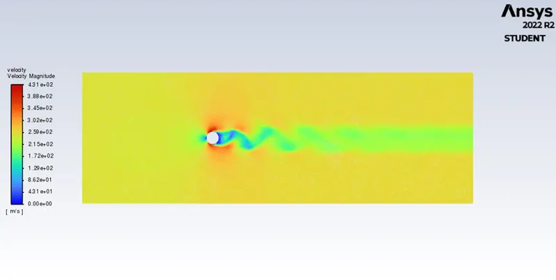
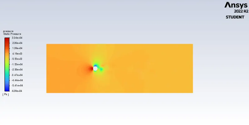
Velocity contour Pressure contour
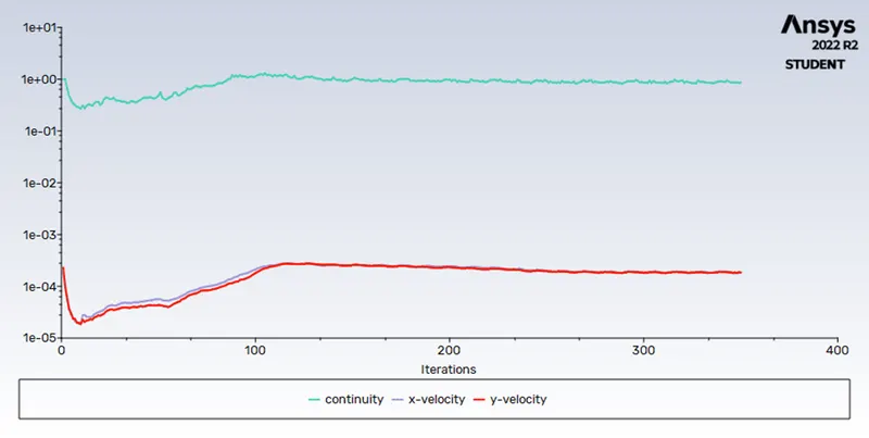
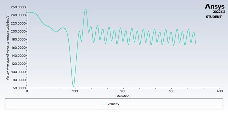
Residuals vertex average velocity
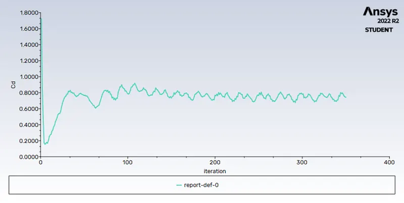
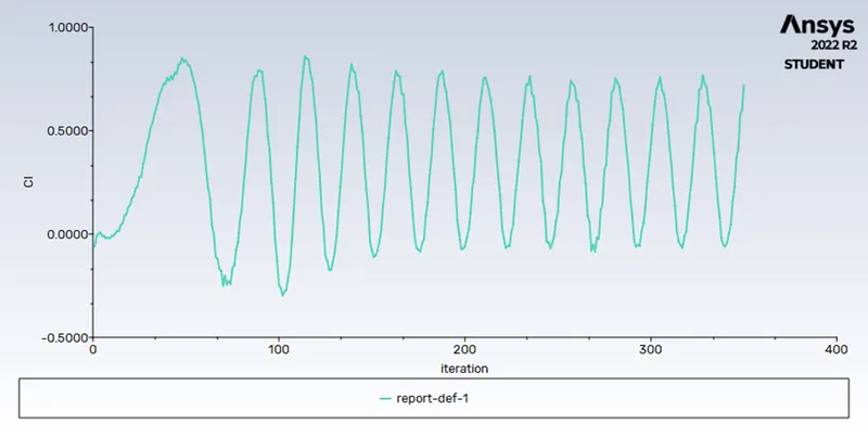
coefficient of drag coefficient of lift
For reynolds number Re=100000
∴ fluid velocity=2500m/s(calulated using reynolds number formula)
dynamic viscosity=0.05 kg/m s
fluid meduim= air-new
fluid density=1kg/m^3
Plots for Re=100000
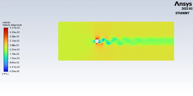
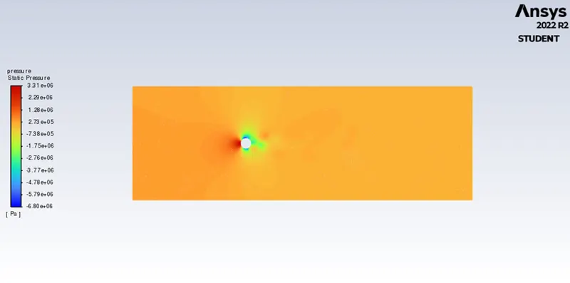
Velocity contour Pressure contour
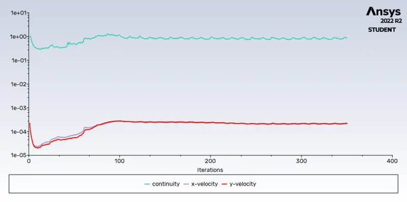
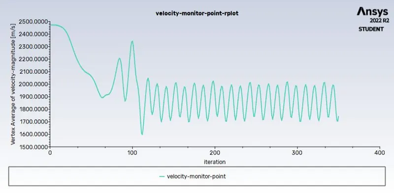
Residuals vertex average velocity
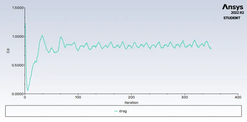
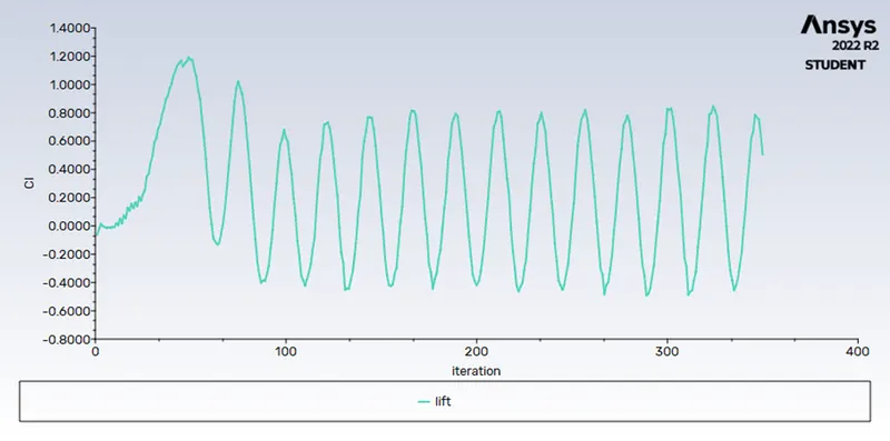
coefficient of drag coefficient of lift
| Reynolds number | coefficient of drag | coefficient of lift |
| 10 | 3.7995 | -0.0016 |
| 100 | 1.5118 | -0.0858 |
| 1000 | 0.5858 | 0.3039 |
| 10000 | 0.7456 | 0.7287 |
| 100000 | 0.8173 | 0.4957 |
| 100(unsteady) |
ii) Simulate the flow with the steady case and unsteady case to calculate the Strouhal number for Re=100 and velocity 2.5m/s.
unsteady flow
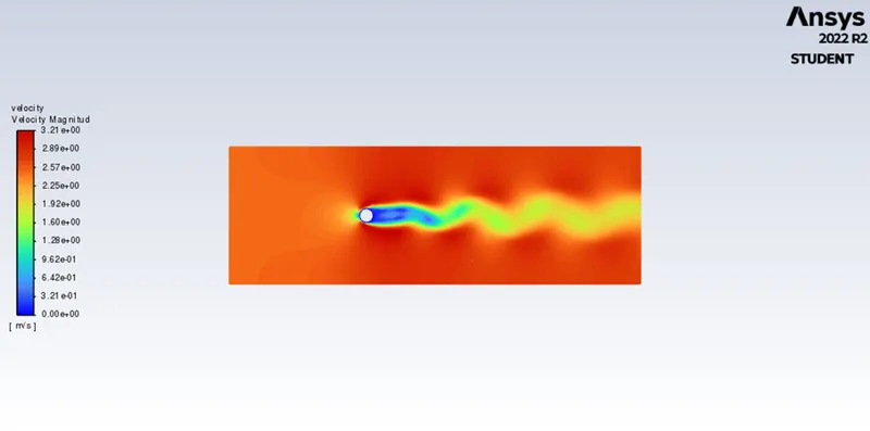
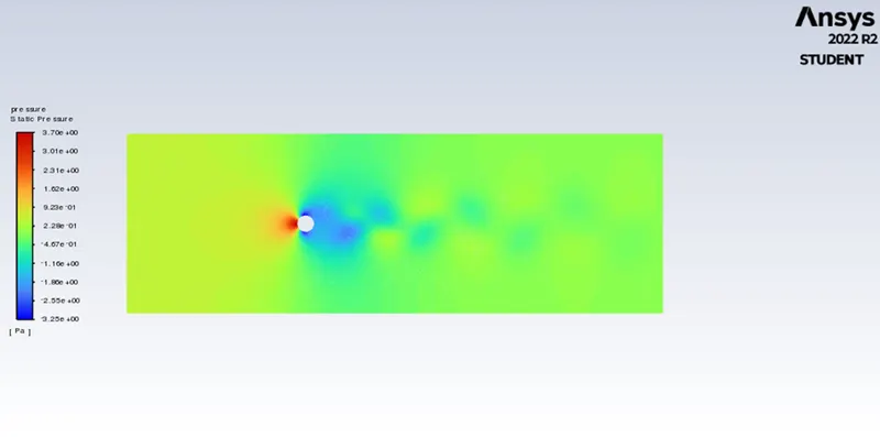
Velocity contour Pressure contour
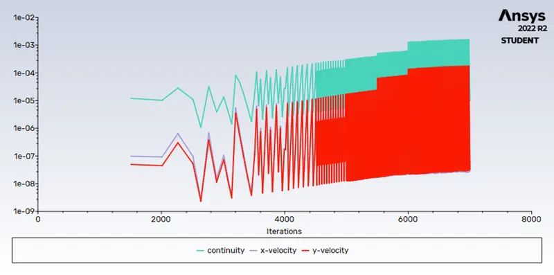
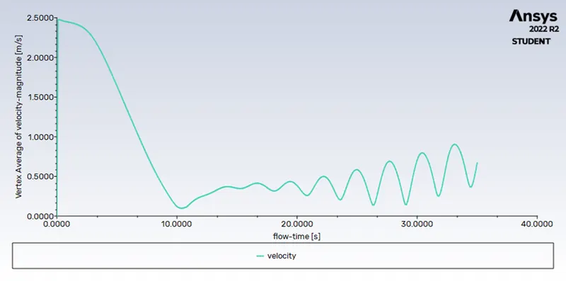
Residuals vertex average velocity
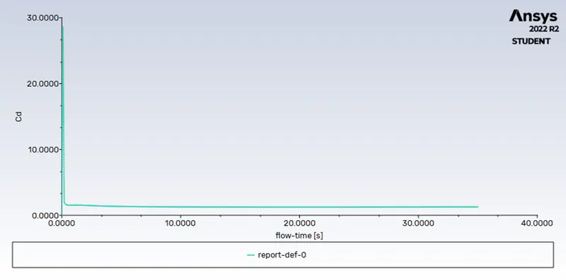
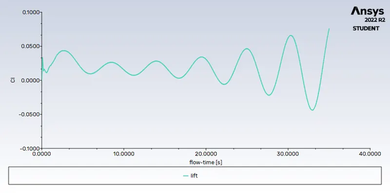
coefficient of drag coefficient of lift
The Strouhal number is defined as St = fstD/U, where fst is the vortex shedding frequency (or the Strouhal frequency) of a body at rest, D is the diameter of the circular cylinder and U is the velocity of the ambient flow.
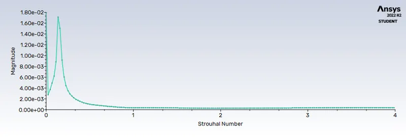
strouhal number=0.140
steady flow for Re=100
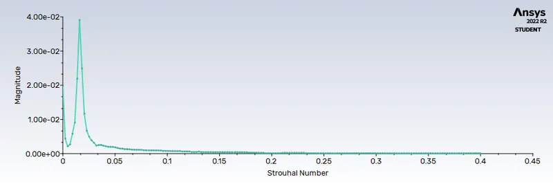
strouhal number=0.016
Conclusion:
For part-1
- Flow over a cylinder was simulated with the steady and unsteady case and calculate the Strouhal Number for Re= 100. and found out that st=0.140 for unsteady flow and st=0.016 for steady flow.
- coefficient of drag & lift and vortex average plots are plotted in order to observe whether the flow is converged and found out the occurence of vortex shedding.
- Contours are reported such as velocity & pressure, in order to observe the flow over a cylinder.
For Part-2
- coefficient of drag and lift over a cylinder were calculated by setting the Reynolds number to 10,100,1000,10000 & 100000 under steady state.
- the effect of Reynolds number on the coefficient of drag were checked and analyzed.
- the coefficient of drag and lift,vortex average velocity were plotted and checked.
- vortex shedding behind the cylinder for differnent reynolds number were generated and animation were created for the observation of vortex shedding.