Week 3 Challenge : CFD meshing on Turbocharger
Aim:For the given model, we need to check for geometrical errors to make appropriate volumes. Create and assign PIDs. Perform surface mesh with the given target lengths as per PIDs and to perform Volumetric mesh for the required volumes.
Introduction: A turbocharger is a forced induction device. It is used to force air into an internal combustion engine. It increases the amount of air entering the engine to create more power. A turbocharger has the compressor powered by a turbine.It is the job of the turbocharger to compress more air flowing into the engine's cylinder. When air is compressed the oxygen molecules are packed closer together. This increase in air means that more fuel can be added for the same size naturally aspirated engine.
Procedure:
step 1: import the model.
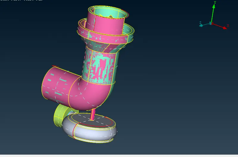
step 2: check for overlapping, single, triple cons surfaces from check-geometry.
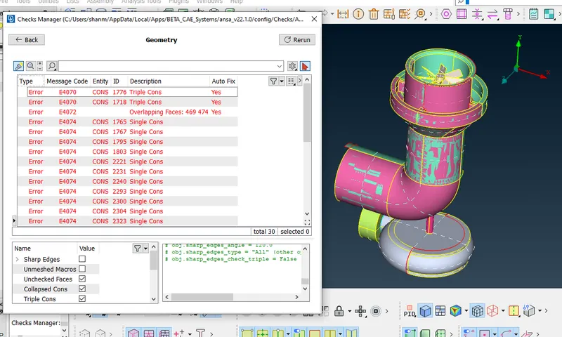
step 3: delete the overlapping surface and solve the single cones and also some cones needs to be solved by creating hotpoints and then creating new surfaces.
creating new hot points for the below marked places and creating new surfaces to solve the single cone.
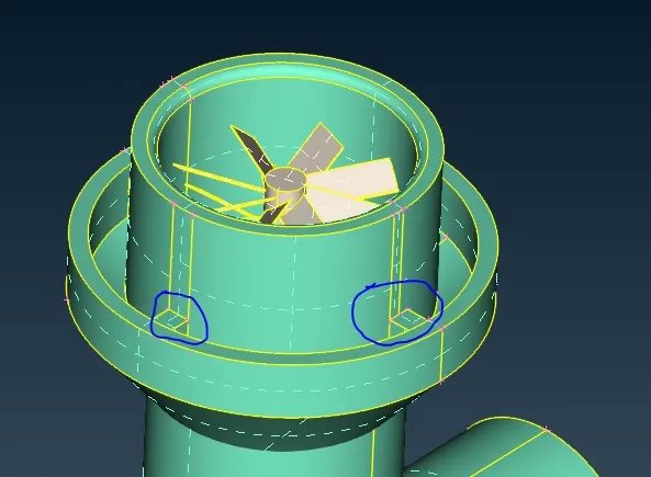
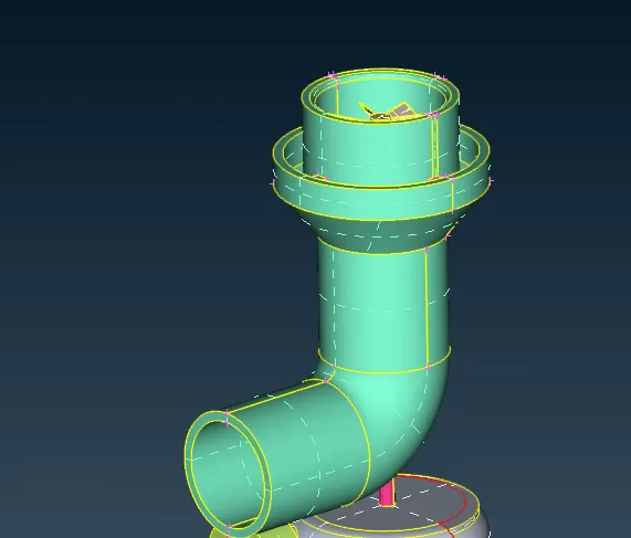
step 4: perform the intersect operation in order to create two surface which are intersecting with each other and delete the remaining single cones.
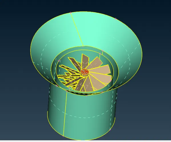
step 5: to solve this below single we need to create multiple hotpoints using parameteric input and create surfaces.
(reason to create multiple hotpints is to obtain smooth surfaces.)
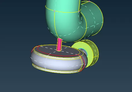
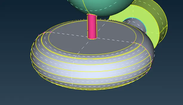
step 6: solve the overlapped suraface of the shaft using project command and delete the remaining suraface
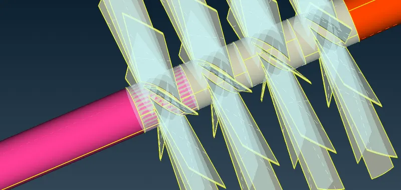
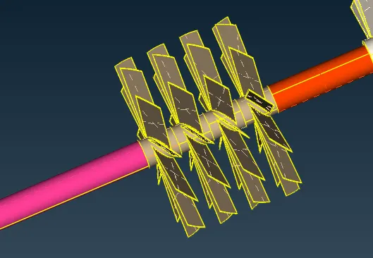
step 7: Need to create cut to seperate from the joining surface of the below snap and delete the face.
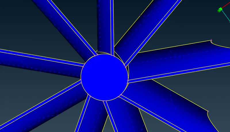
step 8: close all the open surface by creating new surface and start with assigning PID's to the surface.
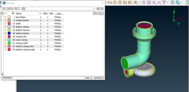
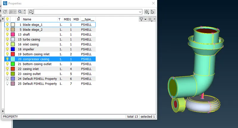
step 9: after assigning PID's check once for single and triple cones using geometry as well as with PID's.
step 10:start with 2D meshing to all the PID's.
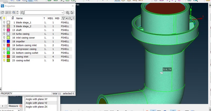
compressor casing lesh length=5mm.
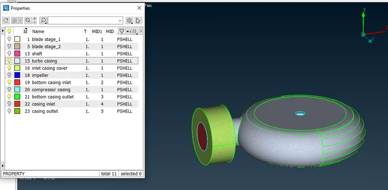
turbo casing mesh length =5mm
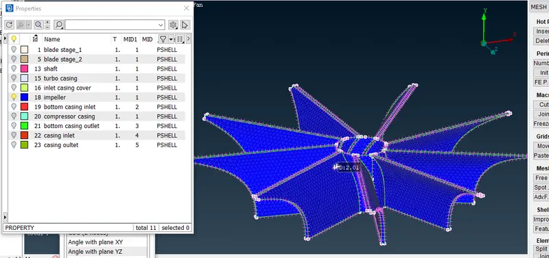
impeller:
shaft, blade stage_1,blade stage_2:
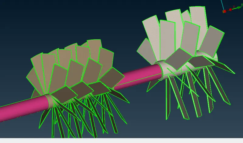
step 10: when two different surfaces are of different mesh length such as impeller and shaft, define the macros length as range between(1-2) in order to avoid unmeshed suraface.
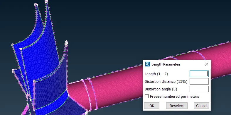
step 11: check and analyze whether any overlapping surfaces are there or any unmeshed surface.
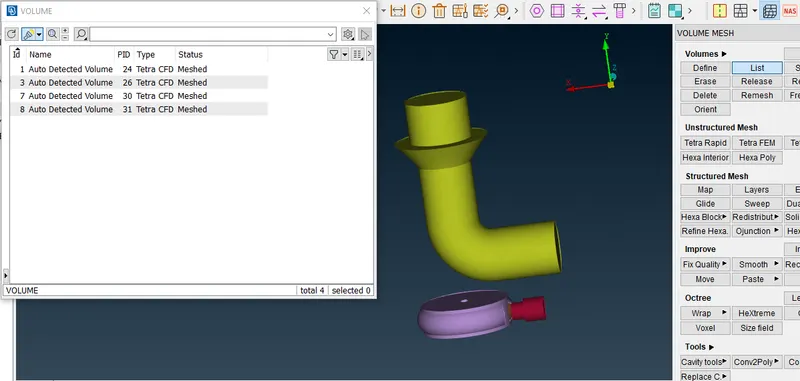
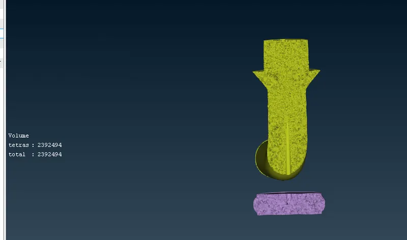
step 12: perform volumetric mesh on the 2D meshed model by using design command for the volumn where the fluid may flow and deleting the unnecessary surfaces and perform tetra mesh on the voulmn.
learning outcomes:
1. was able to learn how to do topology cleanup for the overlapping surfaces and perform advance cleanup.
2. learnt how to give different mesh length to different components and analyze them.
3. Assigning PID's
4.understanding the meshing processes for two contacted surfaces of different mesh lengths.
5. learnt the definition and perform volumetric meshing the solid model and analyzing them by taking cross section.
6. was able the understand the tetra mesh pattern at different location of the volume.
Results:For the given model, geometrical errors were identified and corrected.PIDs were assigned and Performed surface mesh with the given target lengths as per PIDs and Volumetric mesh for the required volumes.
https://drive.google.com/file/d/1shZoUx8FnMJFN_HvscyHxWtxixQMjW8y/view?usp=sharing