Week 9 - Parametric study on Gate valve.
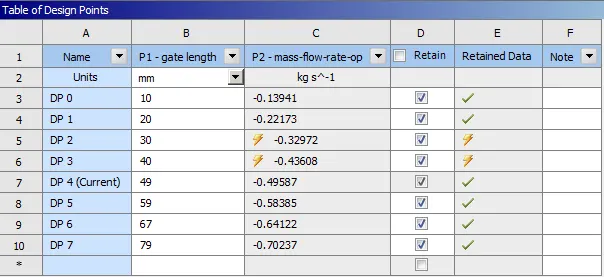
Aim: To perform a parametric study on the gate valve simulation by setting the opening from 10 % to 80%.
objective:
- To Obtain the mass flow rates at the outlet for each design point.
- To Calculate the flow coefficient and flow factor for each opening and plot the graph.
- To Discuss the results of the mass flow rate and flow coefficient.
Introduction:
A gate valve, also known as a sluice valve, is a valve that opens by lifting a barrier (gate) out of the path of the fluid. Gate valves require very little space along the pipe axis and hardly restrict the flow of fluid when the gate is fully opened. The gate faces can be parallel but are most commonly wedge-shaped (in order to be able to apply pressure on the sealing surface).
Gate valves are used to shut off the flow of liquids rather than for flow regulation, which is frequently done with a globe valve. When fully open, the typical gate valve has no obstruction in the flow path, resulting in very low flow resistance. The size of the open flow path generally varies in a nonlinear manner as the gate is moved. This means that the flow rate does not change evenly with stem travel. Depending on the construction, a partially open gate can vibrate from the fluid flow.
Gate valves are mostly used with larger pipe diameters (from 2" to the largest pipelines) since they are less complex to construct than other types of valves in large sizes.
At high pressures, friction can become a problem. As the gate is pushed against its guiding rail by the pressure of the medium, it becomes harder to operate the valve. Large gate valves are sometimes fitted with a bypass controlled by a smaller valve to be able to reduce the pressure before operating the gate valve itself.
Gate valves without an extra sealing ring on the gate or the seat are used in applications where minor leaking of the valve is not an issue, such as heating circuits or sewer pipes.
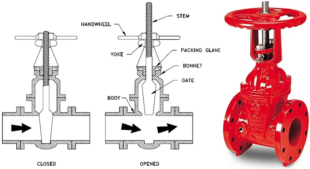
Gate Valve Applications
- Gate valves are used in almost all fluid services such as air, fuel gas, feedwater, steam, lube oil, hydrocarbon, and almost any services.
- Some special gate valve is used in slurry and powder product also, such as knife gate valve.
Advantages of Gate Valve
- Gate valve provides good shutoff
- Pressure drop during operation is very less
- Most of the gate valves can be used as bi-directional
- They are suitable for high pressure and temperature application and require less maintenance
Disadvantages of Gate Valve
- It cannot be used to control the flow.
- A gate valve is slow in operation. Opening and closing take time which is good also as it reduces the chance of hammering.
- When partially open, it creates vibration and noise.
- Repairs, such as lapping and grinding of seats are more difficult due to limited access.
Flow Coefficient:
The flow coefficient of a device is a relative measure of its efficiency at allowing fluid flow. It describes the relationship between the pressure drop across an orifice valve or other assembly and the corresponding flow rate. Mathematically the flow coefficient Cv (or flow-capacity rating of the valve) can be expressed as:
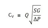
where,
Q is the rate of flow (expressed in US gallons per minute),
SG is the specific gravity of the fluid (for water = 1),
ΔP is the pressure drop across the valve (expressed in psi).
10pa=0.00145038psi
In more practical terms, the flow coefficient Cv is the volume (in US gallons) of water at 60 °F that will flow per minute through a valve with a pressure drop of 1 psi across the valve. The use of the flow coefficient offers a standard method of comparing valve capacities and sizing valves for specific applications that are widely accepted by the industry. The general definition of the flow coefficient can be expanded into equations modeling the flow of liquids, gases, and steam using the discharge coefficient.
Flow Factor:
It indicates how much volume of a fluid flows through a valve at a given time To calculate the flow rate volume of a liquid, the Kv factor, the density of the medium and the pressure difference between input pressure and back pressure must be known.The metric equivalent flow factor (Kv; commonly used in Europe and Asia) is calculated using metric units:
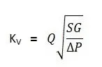
Kv can be calculated from Cv using the equation as given below:
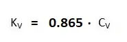
The Kv factor of a valve indicates "The water flow in m3/h, at a pressure drop across the valve of 1 kgf /cm2 when the valve is completely open.
Procedure:
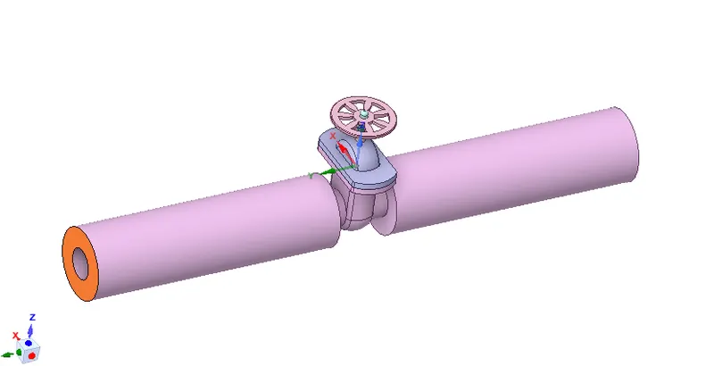
step 1: Import the gate valve file into space claim and extrude the highlight surface on either side to 800mm to conduct the flow analysis.
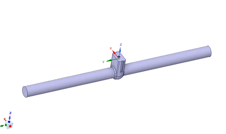
step 2:perform volume extraction operation by selecting the fluid interacting surfaces under prepare in spaceclaim.
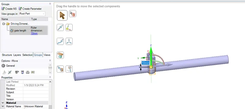
step 3:Hide all the components of the gate valve except gate disc, spindle, using move command under design move the gate disc along the z direction for 10mm so that the flow path is partially open and parameterize this value under groups->create parameter.
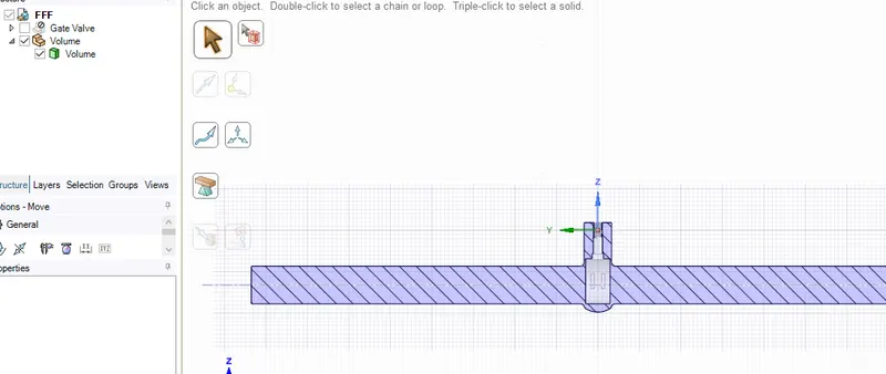
step 4:keeping checked-in of the selected components of gate valve right click on volume->click on update the geometry as per content. Since we are not interested in the analysis of solid geometry, it is suppressed.
case 1:Gate Lift adjustment=10mm in positive z direction.
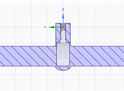
case 2:Gate Lift adjustment=20mm in positive z direction.
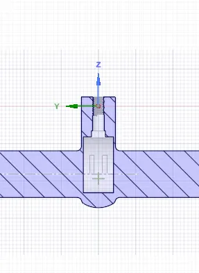
case 3:Gate Lift adjustment=30mm in positive z direction.
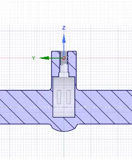
case 4:Gate Lift adjustment=40mm in positive z direction.
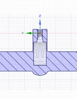
case 5:Gate Lift adjustment=49mm in positive z direction.
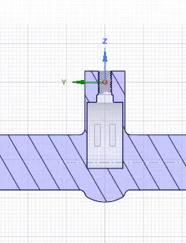
case 6:Gate Lift adjustment=59mm in positive z direction.
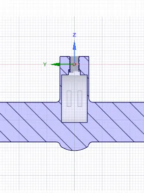
case 7:Gate Lift adjustment=67mm in positive z direction.
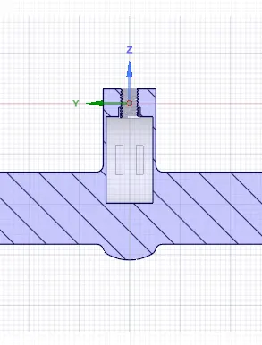
case 8:Gate Lift adjustment=79mm in positive z direction.
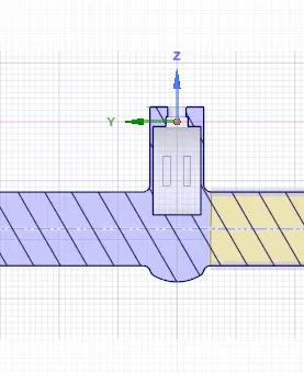
step 5:geometry is defined, the meshing is done. The mesh element size considered was 6mm. the required mesh was generated, a total of 84430 nodes and 418301 elements were generated.
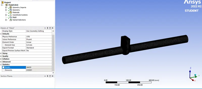
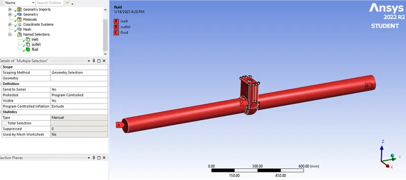
step 6: name selection is created for inlet & outlet and fluid domain.
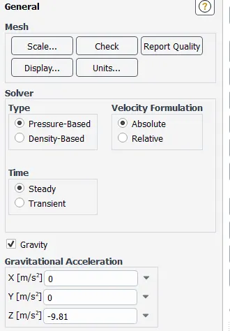
step 7:follow these below steps for performing fluent setup.
Set up:
1. Solver: Steady state
2. Type: Pressure Based
3.velocity formulation:absolute
3. Gravitational Acceleration:
- X: 0
- Y: 0
- Z: -9.81 m/s2
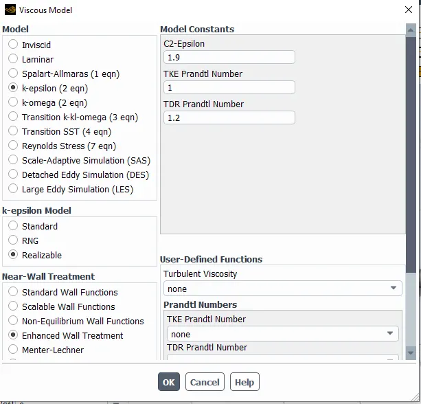
4. Turbulence Model: Realizable k- epsilon with enhanced Wall treatment.
5.Cell Zone Condition:
- Fluid: Water
6. Material Specifications:
- Material: water-liquid (H2o)(l)
- Density: 998.2 Kg/m3
- Viscosity: 0.001003 Kg/m-s
6. Boundaries:
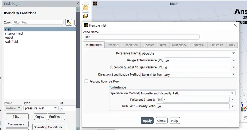
- Inlet: type=pressure inlet;Pressure = 10 Pa(Gauge Pressure)
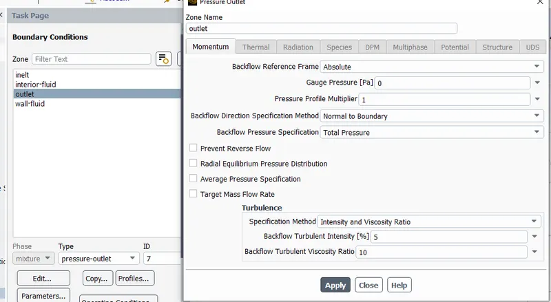
- Outlet:type=pressure outlet; Pressure= 0 Pa (Gauge Presssure)
7. Solution Methods: Coupled
8. Initialization:
- Method: hybrid Initialization
- Number of Iteration: 500
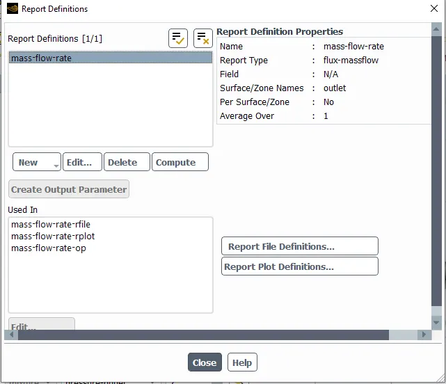
- Report Definitions for the report of Mass Flow Rate at the Outlet is created.
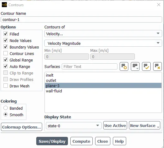
- A plane is created and Contours for Velocity Magnitudes is created.
- Animations for the flow of water inside Gate Valve based on Contours is created.
- After initialization, we can get the correct velocity and calculate the Reynolds No. and from that, we can decide the type of viscous model to use.
Results:
Parametric Study Of Mass Flow Rate
1) Case 1: Lift = 10 mm
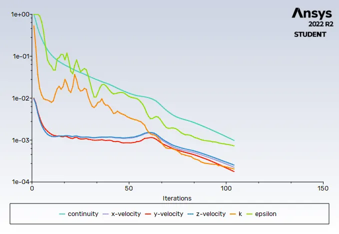
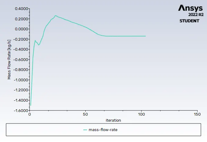
Residuals Mass flow rate
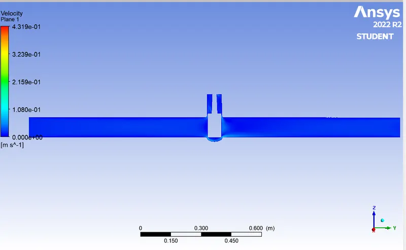
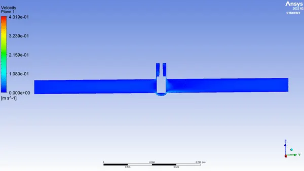
Velocity contour Animation
2) Case 2: Lift = 20 mm
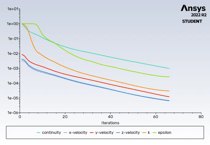
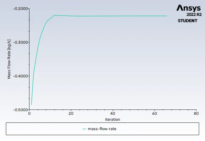
Residuals Mass flow rate
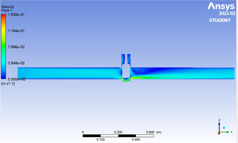
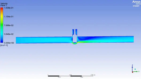
Velocity contour Animation
3) Case 3: Lift = 30 mm
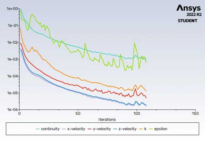
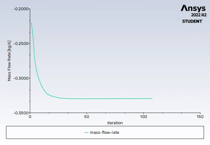
Residuals Mass flow rate
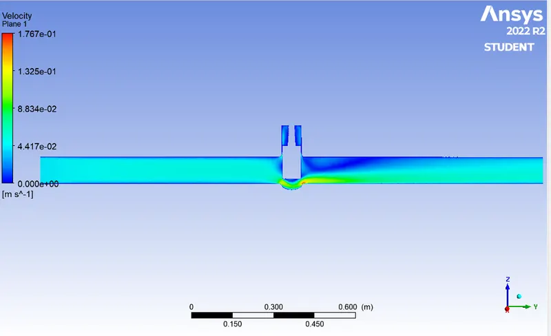
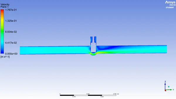
Velocity contour Animation
4) Case 4: Lift = 40 mm
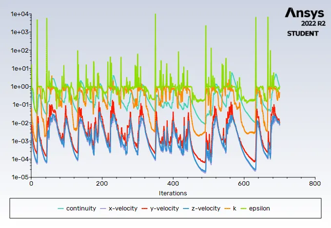
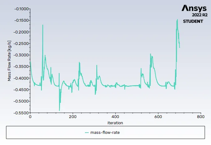
Residuals Mass flow rate
Velocity contour Animation
5) Case 5: Lift = 49 mm
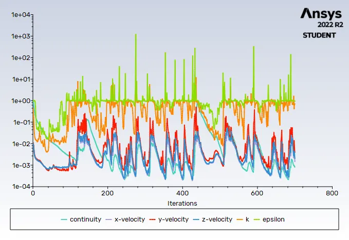
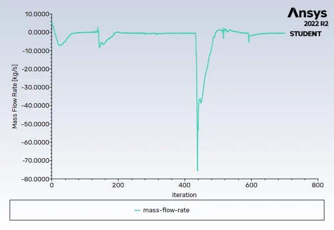
Residuals Mass flow rate
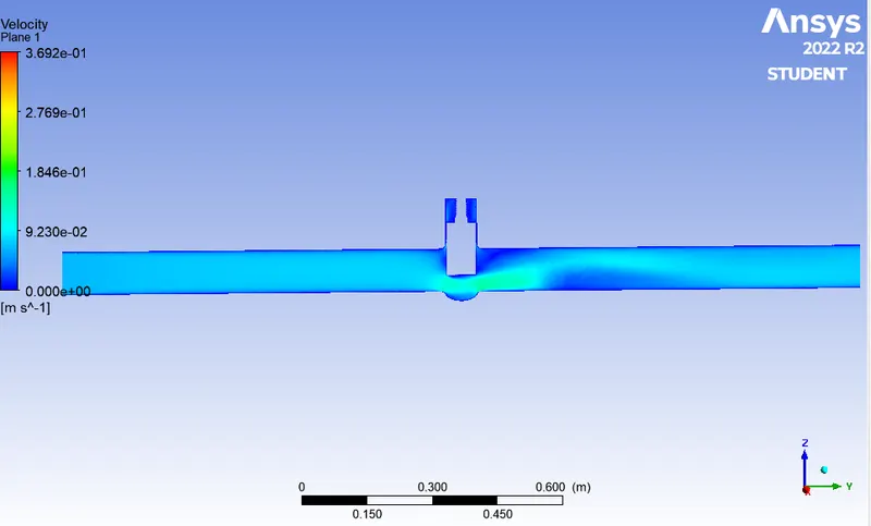
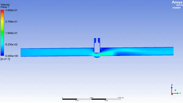
Velocity contour Animation
6) Case 6: Lift = 59 mm
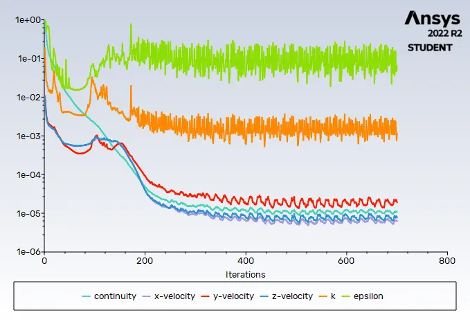
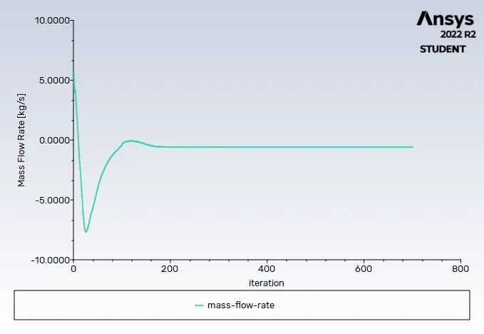
Residuals Mass flow rate
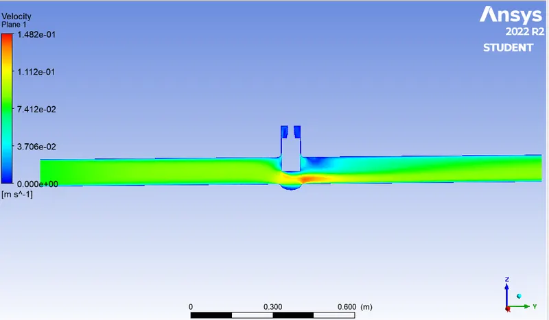
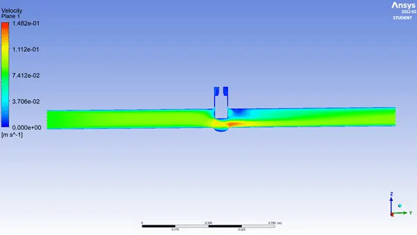
Velocity contour Animation
7) Case 7: Lift = 67 mm
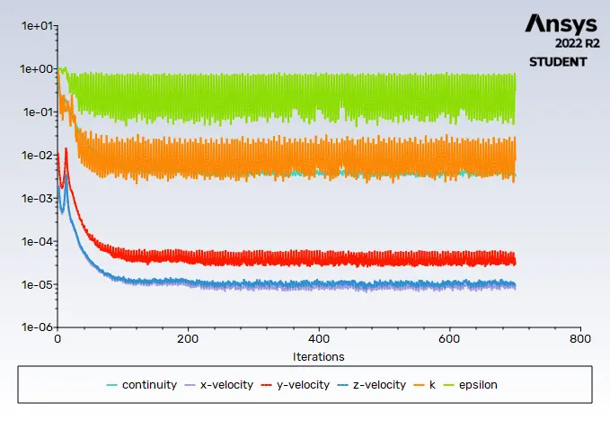
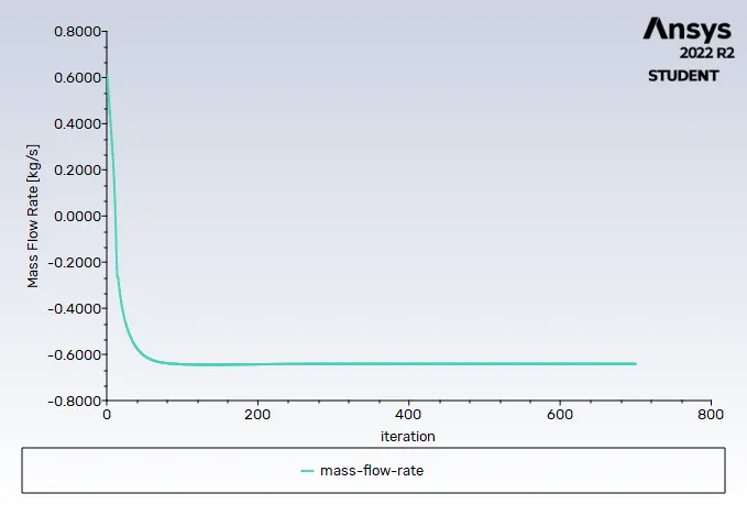
Residuals Mass flow rate
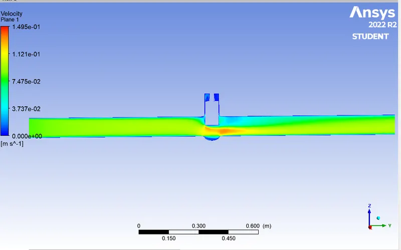
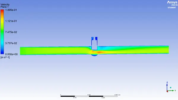
Velocity contour Animation
8) Case 8: Lift = 79 mm
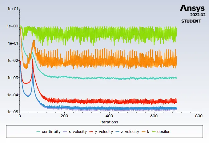
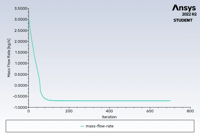
Residuals Mass flow rate
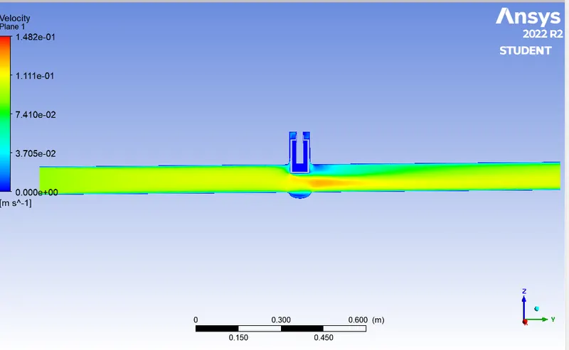
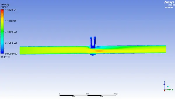
Velocity contour Animation
Tabulations
|
Lift of gate disc (mm) |
flow rate in (kg/s) |
flow rate in (gpm) |
Inlet pressure (Pa) |
outlet pressure (Pa) |
Total pressure drop |
Flow coefficent ( Cv) |
Flow factor (Kv) |
| 10 | -0.13940 | 2.20954 | 10 | -0.1783 | 9.8217 | 57.507 | 49.7435 |
| 20 | -0.22172 | 3.51433 | 10 | -0.48052 | 9.51948 | 90.138 | 77.9693 |
| 30 | -0.32952 | 5.22300 | 10 | -1.06281 | 8.93719 | 130.3911 | 112.7883 |
| 40 | -0.43608 | 6.91201 | 10 | -1.80707 | 8.19293 | 167.029 | 144.4800 |
|
49 |
-0.49586 | 7.85954 | 10 | -2.58322 | 7.41678 | 183.9761 | 159.1392 |
|
59 |
-0.58384 | 9.25405 | 10 | -3.3705 | 6.6295 | 210.1442 | 181.7747 |
| 67 | -0.64121 | 10.16339 | 10 | -4.15975 | 5.8403 | 224.2692 | 193.9926 |
| 79 | -0.70236 | 11.13263 | 10 | -5.05372 | 4.94628 | 238.251 | 206.0871 |
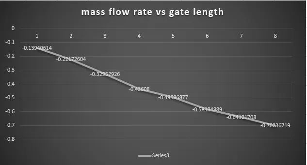
Inference
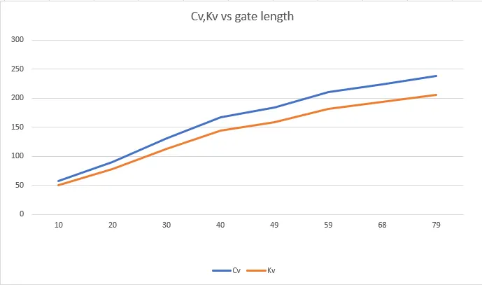
Here for first graph series3 represents fluid flow rate at the opening of the gate valve and in the second graph x axis represents different gate opening length and the y axis represents the value of Kv and Cv.
Here it can be noticed that as the lift of gate disc increses the pressure drop also decreases and the flow coefficient also increases. Further high flow coefficient offers less frictionoll losses and the high pressure flow through the valve with very low pressure drop.
Conclusion:
-
The main purpose of Parametric study allow you to define parameters for evaluation, to define the parameter range, specify the design constraints, and analyze the results of each cases under parameter variation. it is similar to having configurations which enables us to evaluate different simulation. we can further refine the parameters or design constraints as per user requirements till satisfying results are obtained.then we are able to promote that configuration back to the model as a CAD edit. where automatic changes are prompted. Using the parametric study method saves a lot of time in the simulations which require to perform the same operations for different settings multiple times.
- the mass flow rates at the outlet for each design point was obtained.
- Calculated the flow coefficient and flow factor for each opening and plot the graph.
- the results of the mass flow rate and flow coefficient were discussed.