Week 3 - External flow simulation over an Ahmed body.
Aim:
- To perform CFD analysis for one part of Ahmed body and in fluent to use the symmetry boundary condition to perform the simulation.
- To Run the simulation for the velocity of 25 m/sec with the default air properties in fluent.
- plot for Velocity and pressure contours.
- plot the drag coefficient for a refined case.
- Perform the grid independence test and provide the values of drag and lift with each case.
- The vector plot shows the wake region.
Introduction
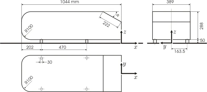
Ahmed body: Optimized external car aerodynamics is necessary to achieve efficient vehicles with minimized fuel consumption, CO2 emissions, and noise, while keeping a good driving stability. Steadily increasing computer power has been raising the importance of simulating the external aerodynamics of vehicles and computing the corresponding aerodynamic characteristic numbers. Model experiments suitable for providing validation data make use of model bodies with geometries characterized by variable parameters, such as the slant angle at the back. One such body is the Ahmed body, a bluff model body of simple shape with basic aerodynamic properties of a vehicle, which has been used for many reference investigations.The dimensions of Ahmed body have been considered as the traditional geometry Ahmed et al. (1984).CFD modeling. The chief purpose of automotive aerodynamics is the reduction of drag, lessening noise emission, increasing fuel economy and eliminating unnecessary lift forces and other origins of aerodynamic unsteadiness which arises at high speeds. The conventional Ahmed reference model has been considered as the standard model in this research work for carrying out numerical simulations for researching on the aerodynamic parameters. The Ahmed body has alike featured like a general car and is broadly utilized for authentication of new codes in the automobile industry. This simple geometric model has a length of 1.044-meter, height of 0.288 meter and a width of 0.389 meter. It consists of cylindrical legs of 0.5-meter radius attached to the bottommost part of the body. The rearmost surface has an inclination of 25 degrees. Ahmed body characterizes the simplified geometry of a ground vehicle as a bluff body type. Its geometry is adequate enough for precise flow simulation and retains few vital practical features relevant to cars. This model aids engineers and designers to generate turbulent flow field surrounding the simple car model by the use of k-epsilon model. In spite of neglecting quite a few numbers of features of a real car like rough underside, rotating wheels, surface projections etc. The Ahmed body generates the crucial features of flow pattern around a car for instance flow impinge-mentation and the displacement around the nose, relative uniform flow of air around the middle portion and flow separation along with the wake generation at the rear. Since the Ahmed body is easy to model, it can be effortlessly utilized for researching various properties like turbulence, drag coefficient, wake region, lift forces, velocity magnitude at various regions of the car, magnitude of pressure around the car which helps in determining what will be resistance, fuel efficiency etc. of the car thereby providing designers a clear idea on which region needs to be optimized for better effectiveness. The main objective of this study being stimulation of turbulent flow within the wind tunnel and around the Ahmed body to capture the flow pattern at the rear and wake region.
Procedure:
step 1: import the Ahmed body in the space claim.
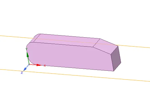
step 2: As the body is perfectly symmetric, we can run the simulation by considering only half of the body. It is considered as best practice where we can save on the number of cells and get the results faster as well. The geometry which is provided with the challenge needs modification. We need to use the 'split body' command in Space Claim to perform the operation and then we can use the symmetry boundary condition in fluent to perform the simulation.
step 3: In order to create enclosure, under prepare -> select enclosure->click on the geometry, uncheck the symmetric dimensions so that we can have flexibility in dimensioning. For frontal distance give 2m, rear= 5m and top= 1m and bottom coincide with geometry legs and sides 0.5m on either side. Then it creates a single large volume enclosure of dimensions by excluding Ahmed body volume from it.
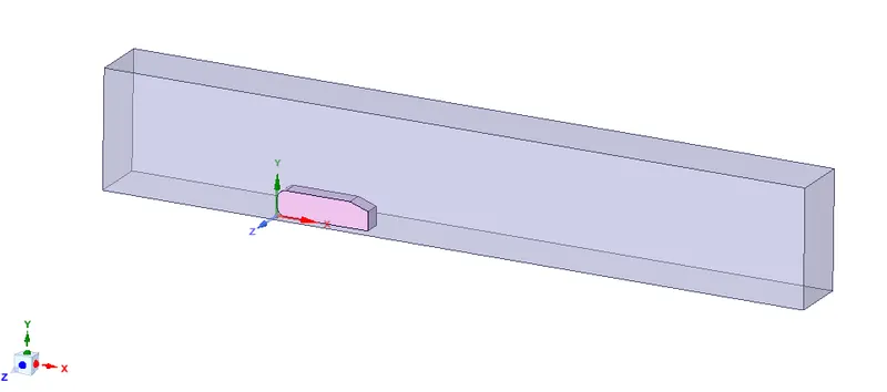
- suppress the Ahmed body for physics in order to avoid creation of mesh for Ahmed body which is not required, since analysis is going to be over the Ahmed body. So we suppress it for physics.
step 4: go back to ANSYS workbench and double click on mesh, initially generate a default mesh with default parameters in order to understand the external flow over the Ahmed body.it can be considered as base mesh.
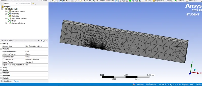
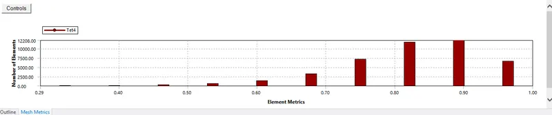
From above plot we can see that quality of mesh is good as the least quality is above 20%
step 5: create name selection for the model in order to define the boundary condition during setup. Which are Inlet, Outlet, Symmetry, Wall, Car-wall.
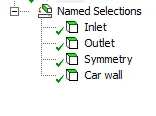
step 6: In Ansys workbench double click on setup, so fluent setup will be opened, the following sequence flow for setting up the model is followed for future cases of different mesh
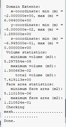
- under domain check the mesh.
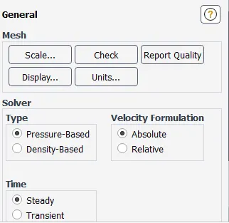
- under physics-> general, update type of analysis to be carried out
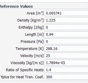
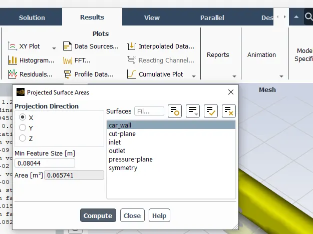
- update the reference values according to the problem, area can be calculated from results->reports->projected areas->select car wall-> compute.
- under viscous, select K-OMEGA SST turbulent model.
- under method ,Select the type of solver (simple taken by default setting) according to the problem.
- input the boundary conditions for inlet velocity, gauge pressure and others.
inlet velocity at inlet- 25 m/sec
outlet- gauge pressure = 0 pa
car wall- type: wall->No slip
- under solution->definitions->create drag and lift reports and plots,
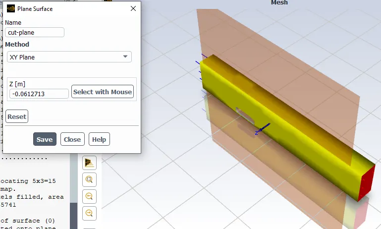
- Next go to the results->create->plane at a distance normal to x,y,z axis which can be used to analyze the velocity and pressure along it.
- Initialize the setup with Hybrid Initialization.
- under result->contour->new->velocity and pressure contours for respective cut-plane. Also add velocity animation.
- Finally simulate the problem for 500 iteration and analyze the Drag, Lift and Residual plots.
step 6 is the common flow line used while setting up the physics model for simulation
Step 7: open cfd post, click on the car wall, create necessary planes, vectors, streamlines, line, point to analyze the flow separation, wave region. but we need to understand previously mentioned phenomenon for better understanding.
point of separation in boundary layer: Boundary layer separation takes place whenever an abrupt change in either the magnitude or direction of the fluid velocity is too great for the fluid to keep to a solid surface. The boundary layer separates when it has travelled far enough in an adverse pressure gradient that the speed of the boundary layer relative to the surface has stopped and reversed direction. The flow becomes detached from the surface, and instead takes the forms of eddies and vortices. The fluid exerts a constant pressure on the surface once it has separated instead of a continually increasing pressure if still attached.
wake region: The flow downstream of a body immersed in a stream, or the flow behind a body propagating through a fluid otherwise at rest. Wakes are narrow elongated regions aligned with the flow direction and filled with large and small eddies. The wake eddies of a bridge pier immersed in a river stream, or of a ship propelled through the water, are often.
step 8: after base analysis create duplicate (cfd fluent flow) and double click on the geometry, create a inner enclosure of dimension as follows
for frontal distance give 0.5m, rear= 1m and top= 0.5m and bottom coincide with geometry legs and sides 0.26m on either side.
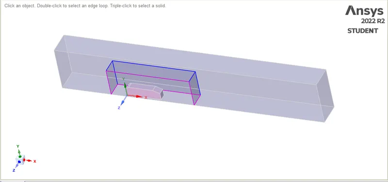
step 9: check for interference and solve them
step 10: under workbench click on share topology to form a connection between the enclosures. Only then these two individual blocks going to exchange information i.e., the meshing is going to be uniform and with perfect connectivity.
step 11: under mesh, reset the generated data and once again perform the name selection for the solid body, face selection -> then press N -> name the selection. In the similar way we name our inlet, outlet, symmetry walls, bottom wall, Ahmed body as car wall.
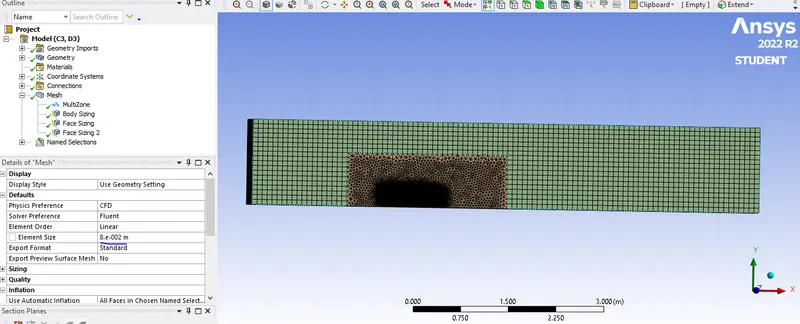
step 12: Now meshing is done in different stages, initially the entire model is generated with mesh of element size=0.1m and under sizing change the capture curvature to yes, all the enclosures and Ahmed body are refined one by one.
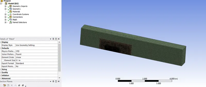
Multizone layer method
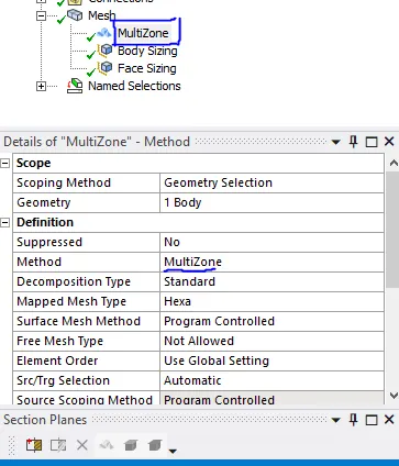
- Now refining mesh for outer enclosure, we can that there is a perfect structure made of straight lines (no complex shape, in 3D made of boxes). So case like this it is recommended to use hexahedral mesh. Hexahedral meshes have the highest quality of all the mesh types
- It can be done by right click on mesh -> insert -> method ->in geometry -> select outer enclosure => Apply method-> multizone
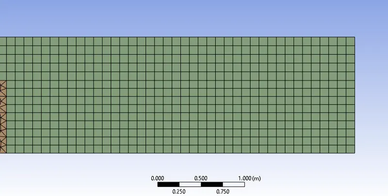
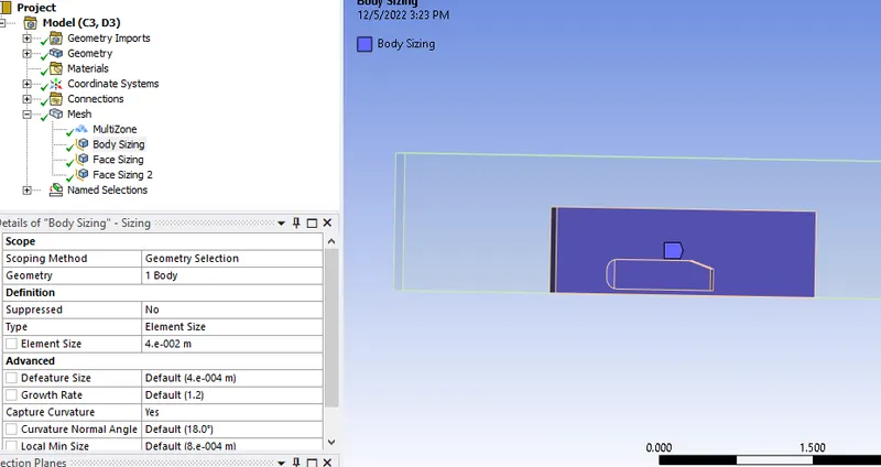
Sizing (inner enclosure):
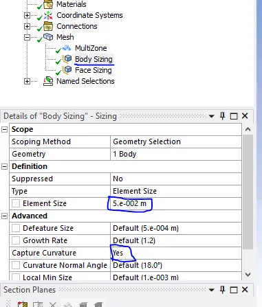
- meshing the inside enclosure finer by using sizing and also in order to capture the circular surfaces(leg) of the Ahmed body, click on capture curvature as highlighted below and change it to yes for legs of Ahmed body.
- Right click on mesh -> sizing -> in geometry ->we select inner enclosure and give size 0.05m -> generate mesh.
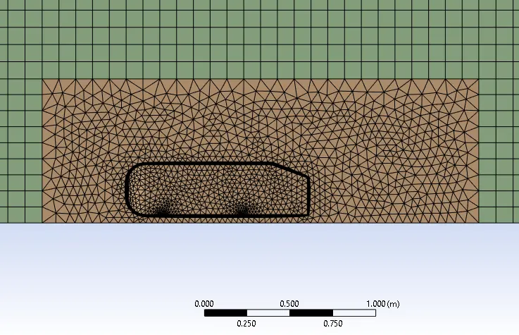
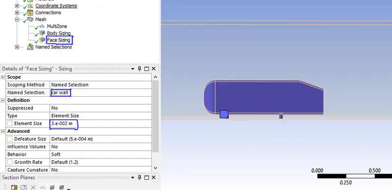
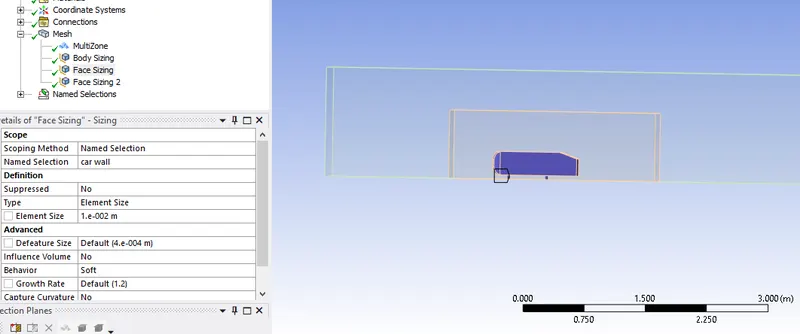
Face sizing (Ahmed body)
Next, face sizing method is introduced for meshing Ahmed body for better refinement, we take the element length as 0.003m
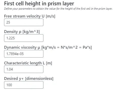
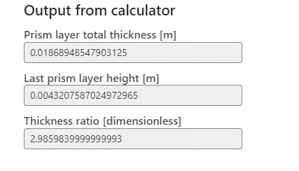
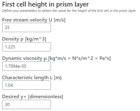
Step 13: Now to analyze the flow over the body we create the inflation layer which helps us in capturing the flow over the boundary layer and the mesh will also be captured along the body perfectly. We take the number of inflation layers as 7, Total thickness value as 1.86966613316728E-02. and it was considered y+ value =100 for turbulent region, it was calculated using y+ calculator from the link here
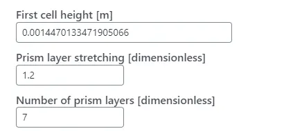
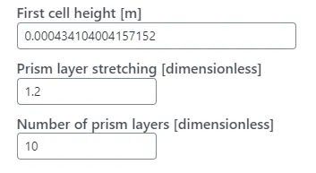
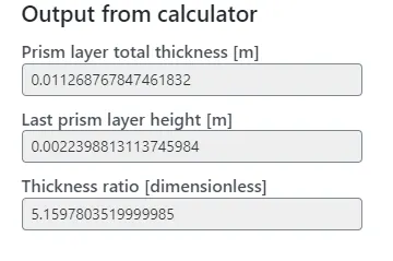
step 14: for case 3 we will go for much refiner mesh with element size for outer enclosure = 0.08m,inner enclosure=0.04m,ahmed body=0.01m and we considered the y+ value =30, number of inflation layer =10, first layer is 0.000434104004157152 and total thickess is 0.011268767847461832 measured from above mentioned link.
Results:
case1: base mesh without inside enclosure and element size = 0.4092m
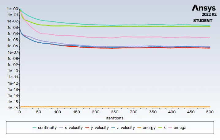
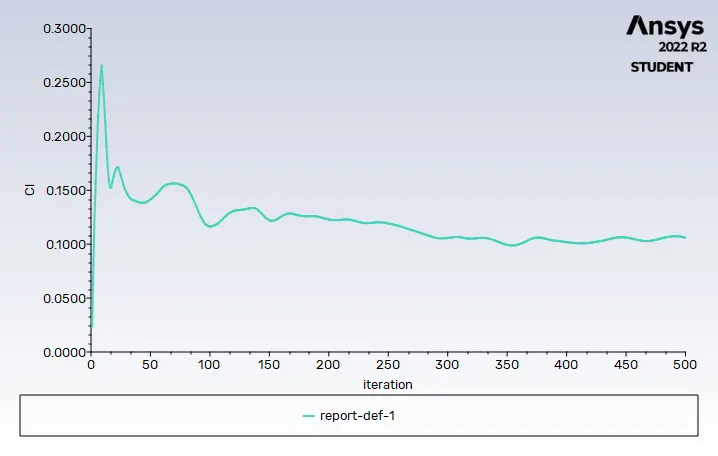
residuals coefficient of lift= 0.1057 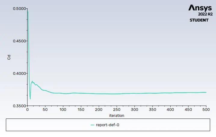
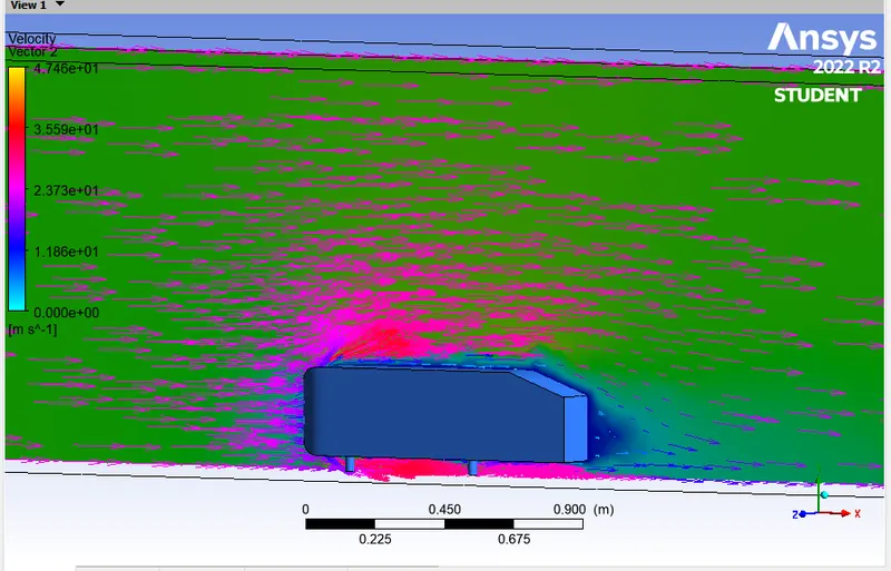
coefficient of drag=0.3907 vector plot
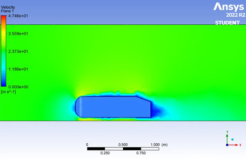
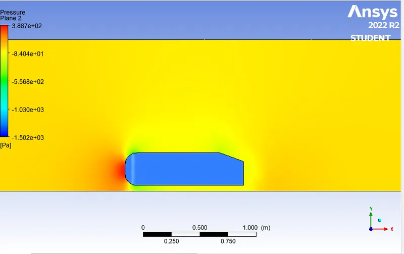
velocity contour pressure contour
case 2: refined mesh with inside enclosure, element size = 0.1m with inflation layer around the car wall.
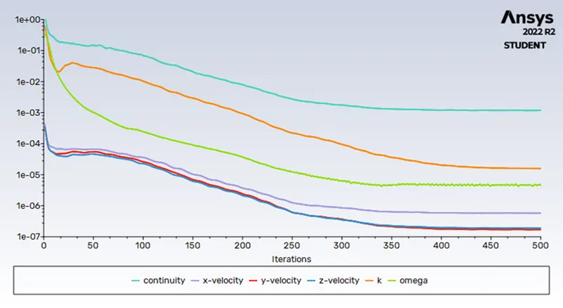
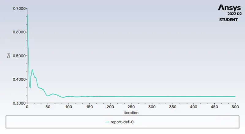
residuals coefficient of drag= 0.3277
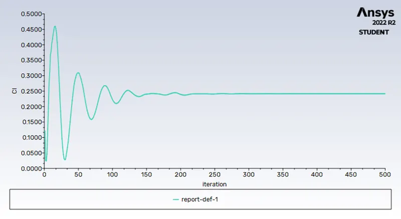
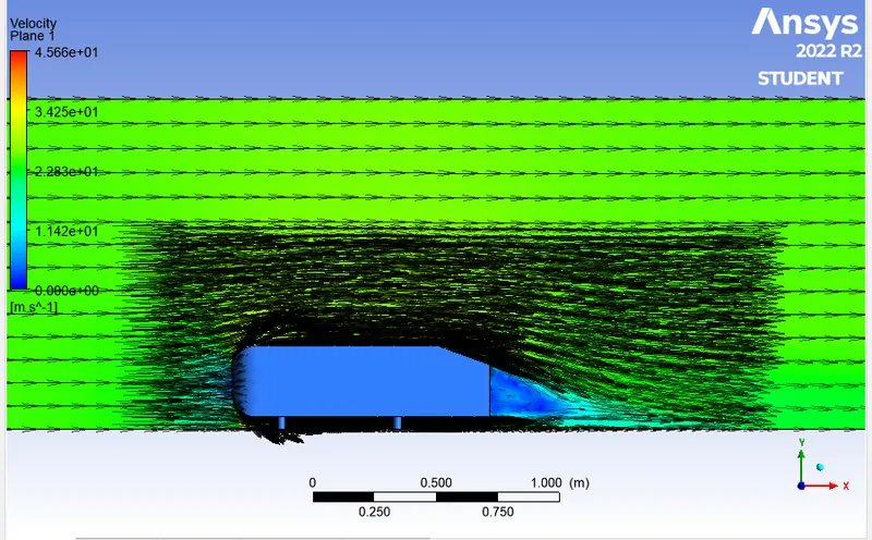
coefficient of lift= 0.2409 vector plot
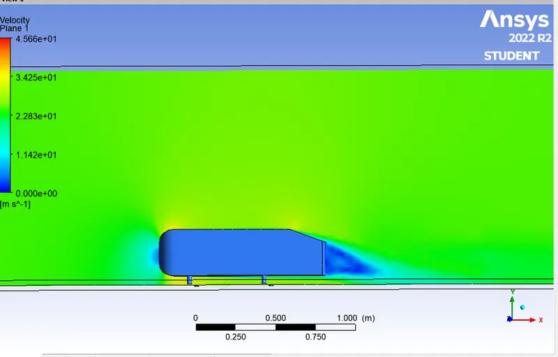
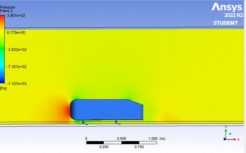
velocity contour pressure contour
case 3: refined mesh with inside enclosure, element size = 0.08m with inflation layer around the car wall.
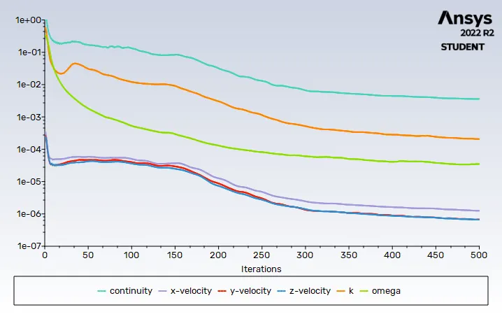
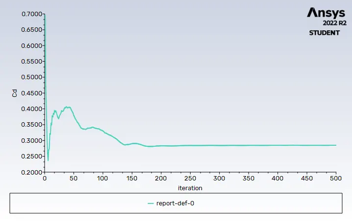
residuals coefficient of drag= 0.2866
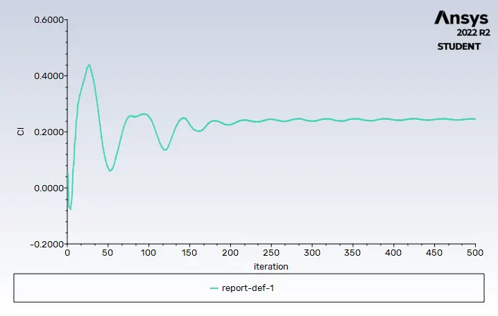
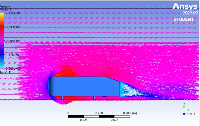
coefficient of lift= 0.2476 vector plot
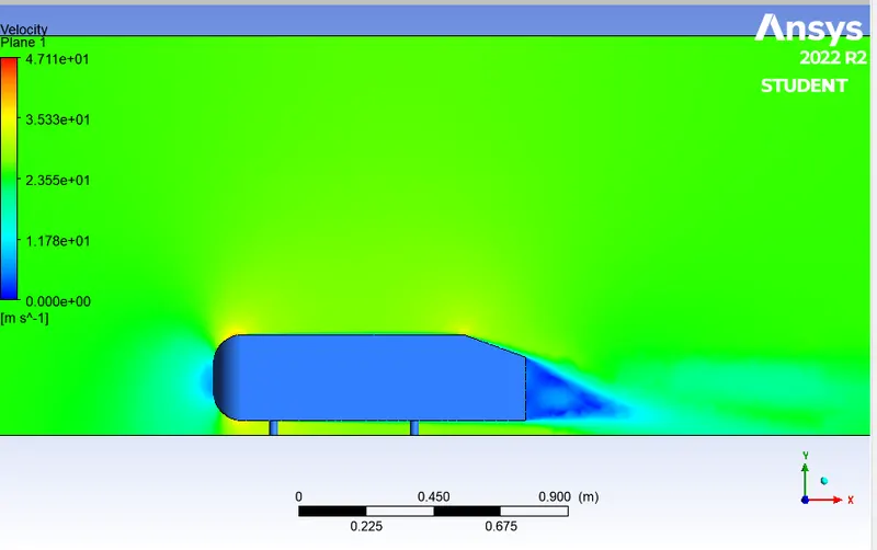
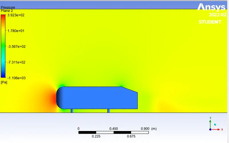
velocity contour pressure contour
| cases | nodes | elements | Cd | Cl |
| 1 | 8565 | 42571 | 0.3907 | 0.1057 |
| 2 | 34762 | 103337 | 0.3277 | 0.2409 |
| 3 | 156246 | 450407 | 0.2866 | 0.2476 |
It can be identified that the values of the experimental result is almost achieved during the second refinement. Thus the grid independence test saves a lot of computational time and convergence can be achieved by using smaller cell sizes for calculation.
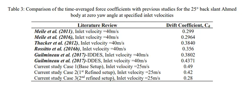
it can be seen that coefficient of drag reduces as the mesh get refined which enables us to identify the wake and flow separation and it can be validated with the experimental value and we can see that we can almost reach the experimental data. as we refine mesh little more we can actually reach the experimental data.the error percentage of coefficient of drag when validating with standard literature is 2.302%
The grid dependency test allows us to see smoother velocity profile. As we make the mesh finer i.e. when we increase the cell counts (closer to the limit), we can see from the vector plots from all the cases, of the velocity that it becomes more and more smoother. One thing is observable that making the mesh finer lets us see the wake region more prominent. From the above mentioned cases, we can conclude that the flow is more defined at lower element size . The finer the mesh gets, the easier it gets in visualizing the contours. Mesh refinement increases the closeness of the resulting values to the true values. From above observations, we conclude that Grid is independent but there is some margin of error which can be caused by a number of other simulation parameters, for example, the turbulence model chosen for this simulation is not the best one for it. Local refinement of the enclosure is a great tool for performing analysis and it improved the results without which wouldn’t have been so accurate and cleared grid dependency in fluent. This study for all practical purposes gives a great real-world scenario of aerodynamic impact on a car body, which when improved can help overcome many challenges faced by automobile.
conclusion:
- CFD analysis was performed for one part of Ahmed body and in fluent we used the symmetry boundary condition to perform the simulation.
- the simulation were runned for the velocity of 25 m/sec with the default air properties in fluent.
- Velocity and pressure contours were plotted and observed.
- the drag coefficient for a refined case were plotted and observed.
- the grid independence test were checked and the values of drag and lift with each case were provided.
- the wake region was shown vector plot for each cases.
References:
[1]: Experiments and numerical simulations on the aerodynamics of the Ahmed body, W. Meile, G. Brenn, A. Reppenhagen, B. Lechner, A. Fuchs
[2]: Flow and Turbulence Structures in the Wake of a Simplified Car Model (Ahmed Model), H. Lienhart, C. Stoots, S. Becker
[3]: Aerodynamic Study of an Ahmed body with the help of CFD Simulation, Indrashis Saha, Tathagatha Mukherjee