Wiring harness design in CATIA V5 - 3D modeling Week 2 Challenge
Aim:To download the connectors & Connector clip cad data & define it as Electrical Connector using Electrical Part design Workbench and to define all the necessary properties to Connectors & Clip.
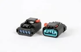
Introduction: Wire harness connectors provide an uninterrupted electronic signal between a wire harness and a power source. Plugs are typically male, while jacks are usually female. Other than that, connectors may differ broadly in size, shape, and dimension as needed by the intended application.
Determining the appropriate type of connector depends on multiple performance factors, such as mating type, insulation needs, power contacts, and signal contacts. Configurations may also vary, with options including wire-to-wire, board-to-board, or board-to-wire. Connectors come in multiple designs, with 2-, 3- or 4-pin connectors being standard. When selecting a connector, it is crucial to know the necessary:
- Current rating
- Circuit density and size
- Engagement force
- Wire size
- Operating voltage
- Agency approvals
- Price per circuit
Step involved:
These following steps are general criteria we use to open the downloaded file
- Download connector and connector clip cad data (.stp or .igs) from the given link.
- unzip the compressed files abd save it in the path.
- Either we can open the cad files in CATIA by clicking on File->Open->select the path or drag and drop into catia V5 window.
Following steps for are for the connectors downloaded
1. C-DT06-08SA
- In part design we create a point on the connector, at the centre of the bundle connection point for the bundle entry.
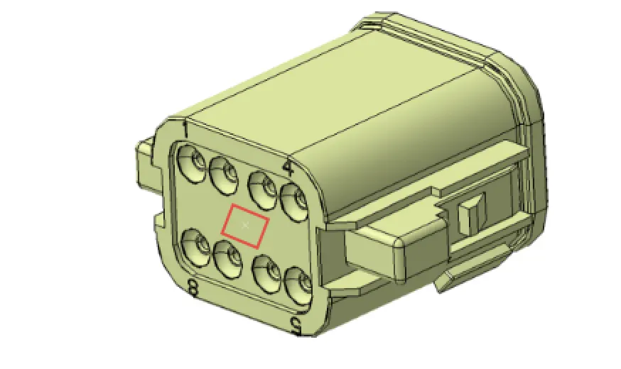
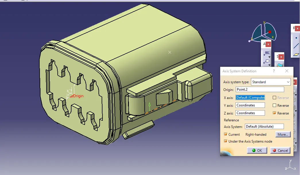
- Next we create another point for connector connection point and add an axis system to the point at the connector connection point where the x-axis should be towards the locking of the connector, the y-axis should be normal to the surface of connector and the z-axis should either be facing up or down.
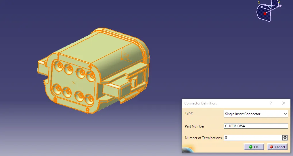
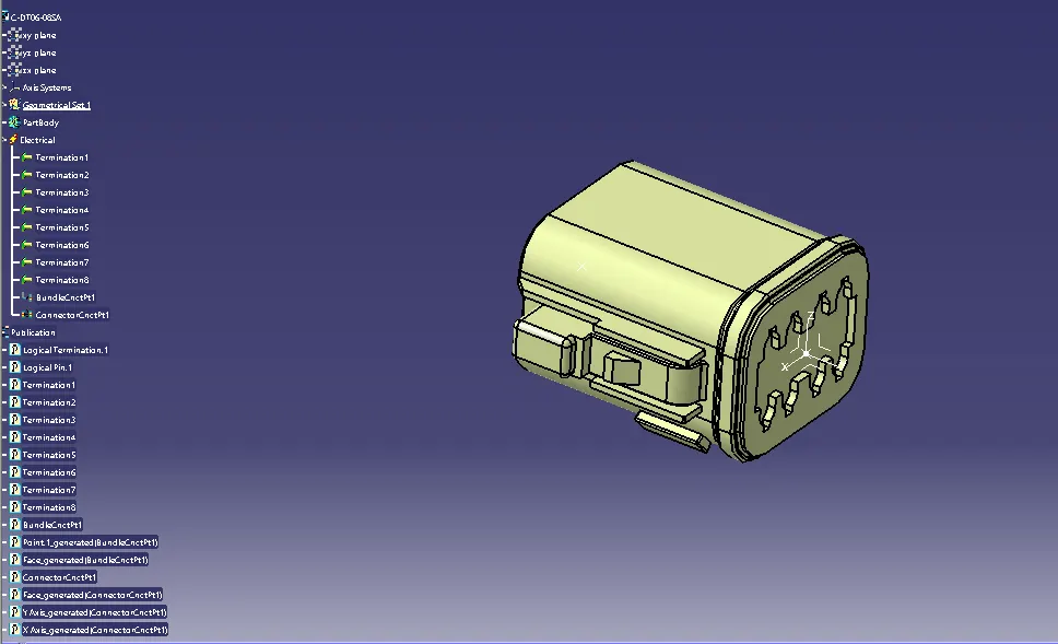
- After geometrical parameters are defined, open the electrical part design in the start menu and then we define the connector which has 8 terminations.
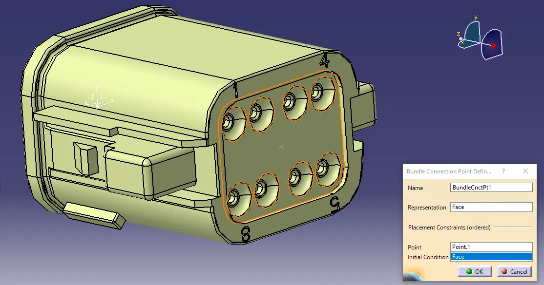
- Next we define bundle connection point where for representation we select bundle entry surface (face) and for the point, we select created bundle entry point (point.1) and for initial condition, again we select theface.
- Next to define the connector connection point in that at representation we select point.2 which was created with axis system and at contact we select face of the connector connection side and for coincident we select y-axis and orientation we select x-axis.
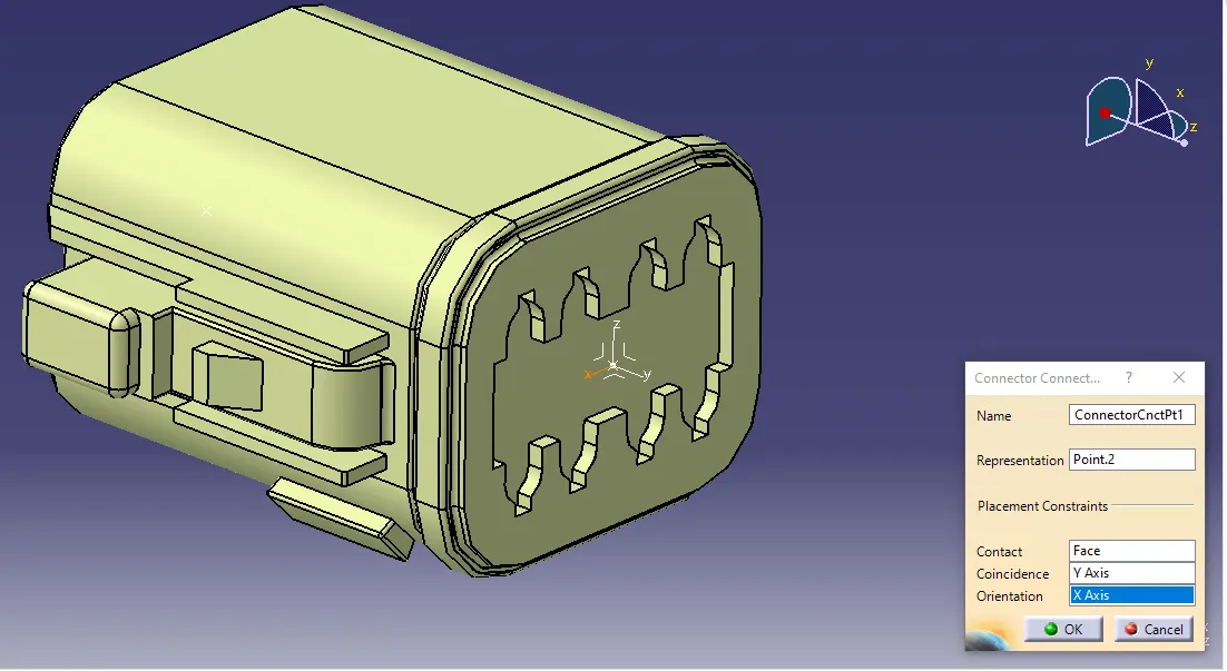
- The above steps are followed to define the bundle and connector connection point because by this input definitions the wires(bundle) is directly connected to the bundle connection point and the connector connects to another connector, all the electrical parameters defined are visible on the tree structure.Now this connector is defined with electrical properties using electrical part design workbench.
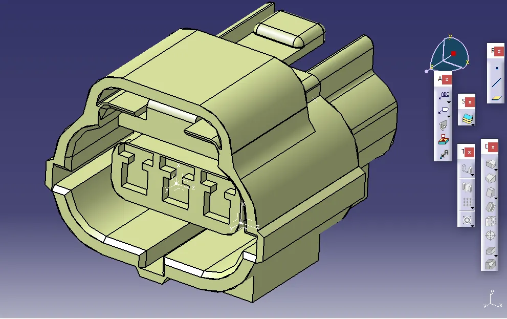
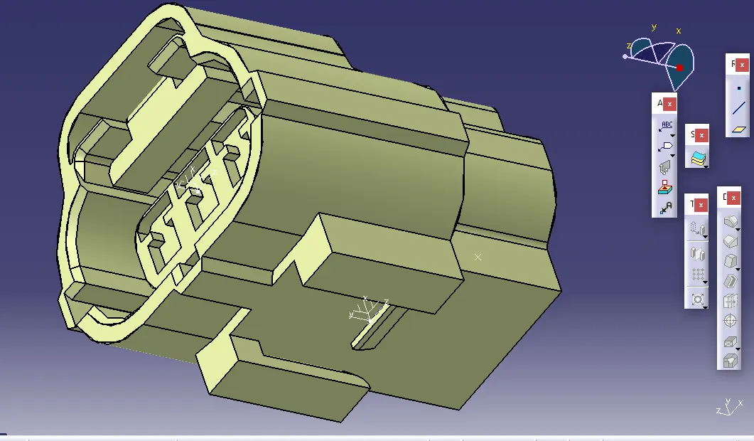
2. C-2-174357-2
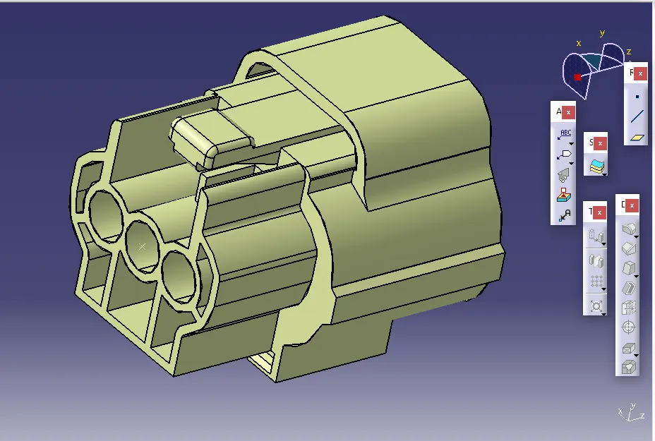
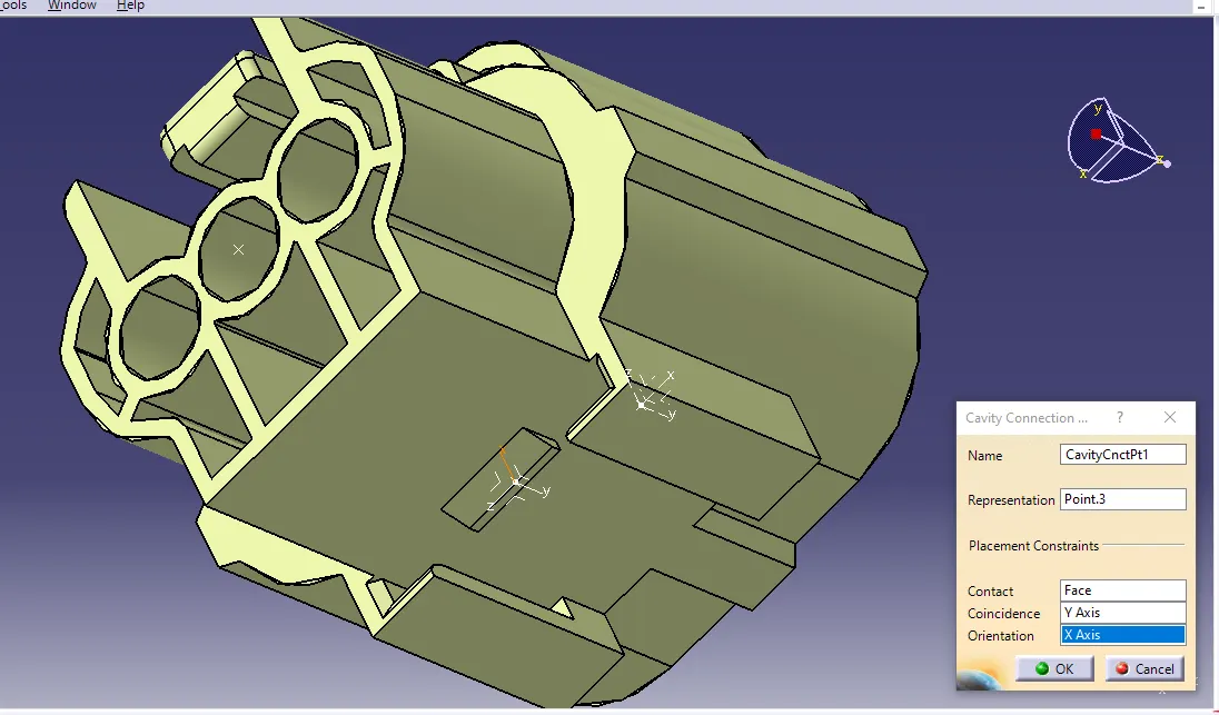
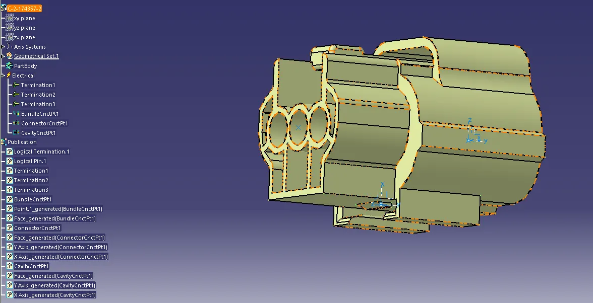
- Defining this connector with electrical parameters is the same as the first connector except this connector has an additional connection point(cavity connection point).
- In part design we create a point at the centre of the face where the mounting clip is going to fit and then add the axis system to the point where the x-axis should point towards the locking and y-axis should be normal to the surface and the z-axis should either face up or down.
- Now in electrical part design and define all the connection points(bundle connection point and connector connection point as we defined for the first connector).
- for defining the cavity connection point at representation we select point.3 and at contact we select the face and at coincident we select y-axis and at orientation we select x-axis.
3.C-0085229-01-3
- This is a mounting clip which is to be fitted with the above connector.
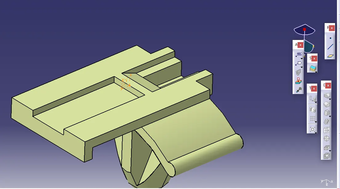
- We create a point at the face of the clip which is fitted to the connector, and then we add axis system to the point same as the above two connectors.
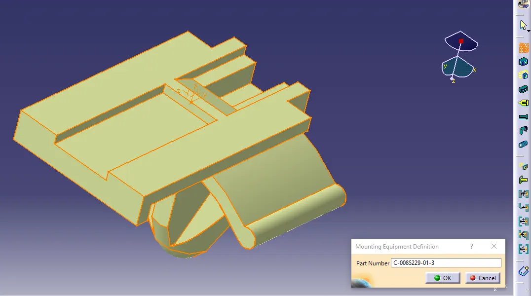
- Following in electrical part design we first define the mounting clip as mounting equipment.
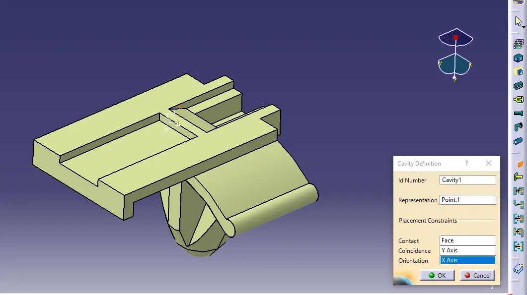
- Then we add the cavity connection point to the clip at point.1.
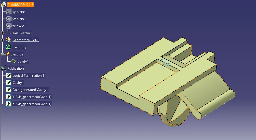
- After defining the cavity connection point we successfully defined this component with electric parameters.
Conclusion: the connectors & Connector clip cad data were downloaded & defined it as Electrical Connector using Electrical Part design Workbench and we also defined all the necessary properties to Connectors & Clip.