Week 5 - Rayleigh Taylor Instability
Rayleigh Taylor Instability
The Rayleigh-Taylor Instability or RT instability (after Lord Rayleigh and G.I. Taylor) is an instability of an intgerface between two fluids of different densities which occurs when the lighter fluid is pushing the heavier fluid. Examples include the behaviour of water suspended above oil in the gravity of earth, mushroom clouds like those from volcanic eruptions and atmospheric nuclear explosions, supernova explosions in which expanding core gas is accelerated into denser shell gas, instabilities in plasma fusion reactors and inertial confinement fusion.

Water suspended atop oil is an everyday example of Rayleigh–Taylor instability, and it may be modeled by two completely plane-parallel layers of immiscible fluid, the more dense on top of the less dense one and both subject to the Earth's gravity. The equilibrium here is unstable to any perturbations or disturbances of the interface: if a parcel of heavier fluid is displaced downward with an equal volume of lighter fluid displaced upwards, the potential energy of the configuration is lower than the initial state. Thus the disturbance will grow and lead to a further release of potential energy, as the more dense material moves down under the (effective) gravitational field, and the less dense material is further displaced upwards. This was the set-up as studied by Lord Rayleigh. The important insight by G. I. Taylor was his realisation that this situation is equivalent to the situation when the fluids are accelerated, with the less dense fluid accelerating into the more dense fluid. This occurs deep underwater on the surface of an expanding bubble and in a nuclear explosion.
As the RT instability develops, the initial perturbations progress from a linear growth phase into a non-linear growth phase, eventually developing "plumes" flowing upwards (in the gravitational buoyancy sense) and "spikes" falling downwards. In the linear phase, the fluid movement can be closely approximated by linear equations, and the amplitude of perturbations is growing exponentially with time. In the non-linear phase, perturbation amplitude is too large for a linear approximation, and non-linear equations are required to describe fluid motions. In general, the density disparity between the fluids determines the structure of the subsequent non-linear RT instability flows (assuming other variables such as surface tension and viscosity are negligible here).
Practical CFD models adapted for mathematical analysis of RT waves
The various models used for analysis of Rayleigh-Taylor waves are as follows:
- SPH method (Smoother Particle Hydrodynamics) method
SPH is a computational method used for simulating the mechanics of continuous media, including fluid flow. It can be used to model fluid motion due to several benefits over traditional grid-based techniques. SPH guarantees conservation of mass without extra computation since the particles themselves represent mass. Moreover, SPH computes pressure from weighted contribution of neighbouring particles rather than by solving linear systems of equations. Lastly, it creates a free surface for two-phase interacting fluids directly since the particles represent the denser fluid and empty space represents the lighter fluid. - Mass diffusion model
The mass diffusion equation describes the transport of mass and energy due to model viscosity and hence drives actual mixing in the fluids. Even if any configuration is Rayleigh-Taylor unstable, the diffusion process could be responsible for significant mixing if the viscosity is sufficiently large. - Single fluid model
A typical approach used for the analysis of two-phase flows is a mixture model. Here, individual fluid phases are assumed to behave as a flowing mixture described in terms of the mixture properties. The applied single fluid model is a five-equation model consisting of the mass, momentum and energy equations for a vapour/liquid mixture, and 2 equations describing the formation and growth of the liquid phase.
> Potential flow model
This model is valid for all instability changes from the linear stage, through the early non-linear to the asymptotic stage. However, it is limited to Atwood number = 1. In this model, single mode perturbation expands the flow equations to second order around the bubble tips, hence obtaining an ordinary differential equation for the bubble velocity.
> Buoyancy drag model
This model is valid for any Atwood number, but limited to the non-linear stages of the instability. It uses ordinary differential equations to evolve the width of the mixing layer. The bubble, or spike amplitudes are described by balancing the inertia, buoyancy and drag forces. This model cannot compute for multiple mixing interfaces, and cannot be extended to 3 dimensions. As a rule, it does not address demixing, also known as counter gradient transport (reduction of total fluid masses within the mixing zones). To overcome the above problems, 2 or multifluid models have to be used.
> Besnard-Harlow-Rauenzahn (BHR) model
It is a more advanced version of the single-fluid model. The BHR model is based upon the evolution equations arising from second order corelations and gradient diffusion approximations. Using a mass-weighted-average decomposition, the original BHR model includes the full transport equations for Reynolds stresses, turbulent mass flux velocity, density fluctuations and the turbulent kinetic energy dissipation rate. - Two fluid model
In the two-fluid model, separate set of governing equations for the vapour and liquid phases are used. The interaction between the droplets and the heat exchange between the liquid phase and the solid boundary are not accounted for. However, the velocity slip between the vapour and the liquid phase in this model is taken into account.
- Multi fluid model
These models use a separate set of equations for each fluid in addition to the main flow equations and provide an accurate modelling framework for demixing by correctly capturing the relative motion of the different fluid fragments. - Turbulence models
Turbulence models predict the average mixing behaviour in flows that are on average one or two-dimensional. The equations governing turbulent flows can only be solved directly for simple cases of flow. The turbulence models offer simplified constitutive equations that predict the statistical evolution of turbulent flows.
> Two equation K-L turbulence model
It involves equations for turbulent kinetic energy (K) and turbulent length scale (L). The starting point for deriving the model equations are the buoyancy-drag models for the self-similar growth of RT instabilities.
> Three equation K-L-a turbulence model
The three equation model was developed as an extension to the two equation K-L model by including a third equation for the turbulent mass-flux velocity (a).
> Four equation K-L-a-b turbulence model
The four equation model was developed as an extension to the three equation K-L-a model by including a fourth equation for density-specific volume covariance. This model can accurately reflect the effects of the changes in the density fluctuations.
Aim of project
- To simulate the Rayleigh-Taylor instability for Air and Water using 2-dimensional approach
- To simulate the Rayleigh-Taylor instability for Water and a user defined fluid
- To compare 2 cases of fluids and study the effect of Atwood number on the RT instability
Baseline simulation [mesh - 0.5mm] [Air and water]
Geometry
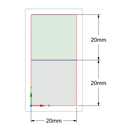
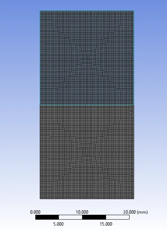
The geometry for this project is fairly simple. It is a transient 2D simulation with 2 coplanar squares having a common edge. At the start of the simulation (t=0s), the square on top denotes water (or the heavier fluid) and the square on bottom denotes air (or the lighter fluid).
Shared topology is also enabled to get a conformal mesh, which is necessary to get a smooth transition during the analysis of the RT instability.
Mesh
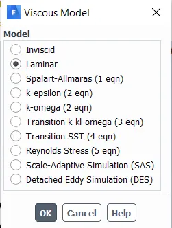
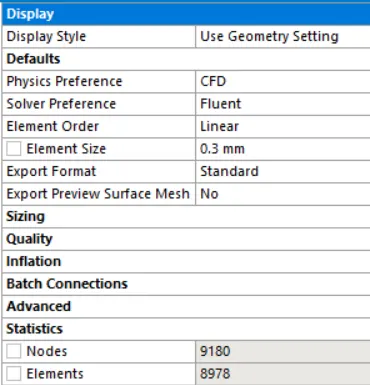
For the baseline simulation, a mesh size of 0.5mm is used. As the geometry is a simple 2D figure, no methods were needed to be used.
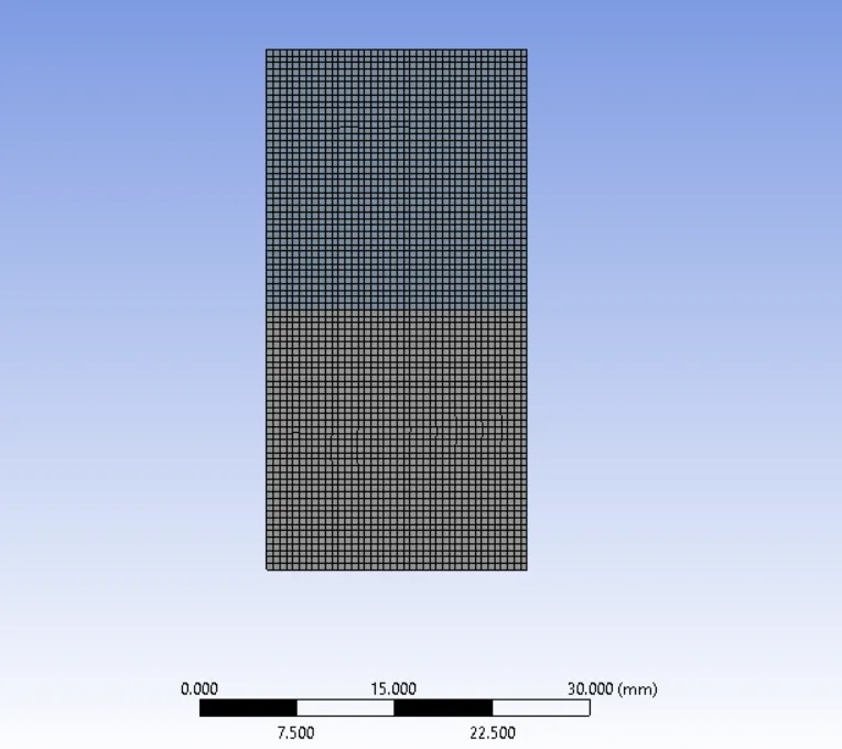
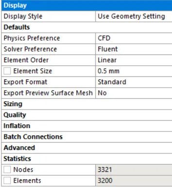
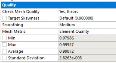
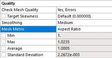
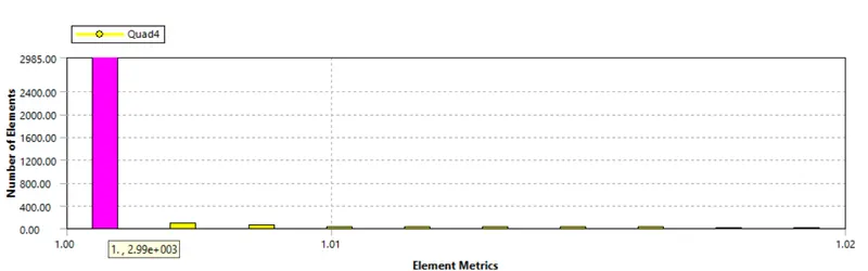
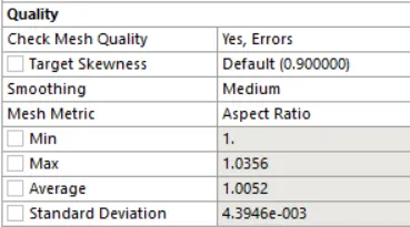
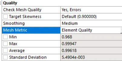
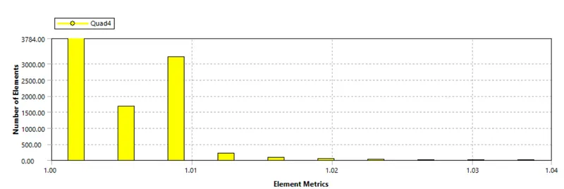
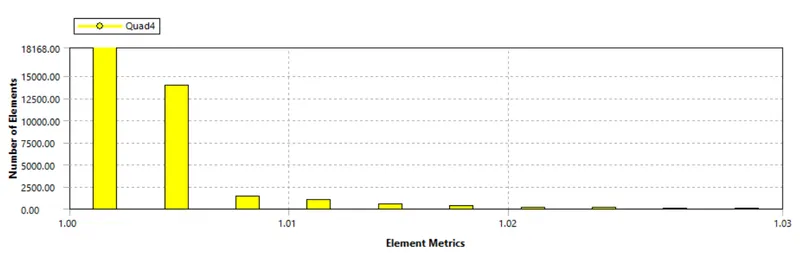
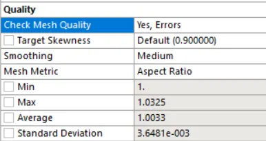
The mesh quality was measured in terms of the aspect ratio. Almost all of the cells had an aspect ratio of 1. Other cells having an aspect ratio not more than 1.02. So a very good quality mesh was observed. The average mesh quality was noted to be 99.87%.
Setup
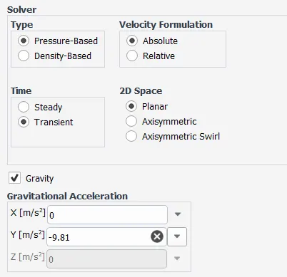
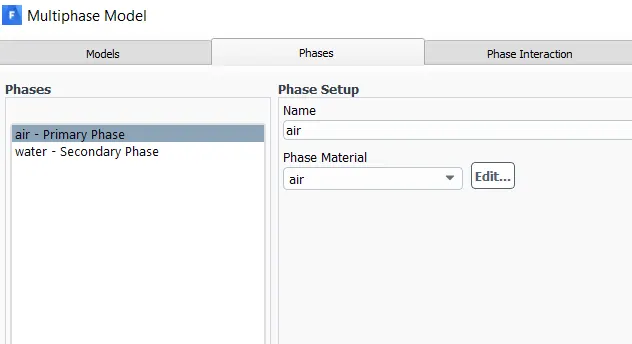
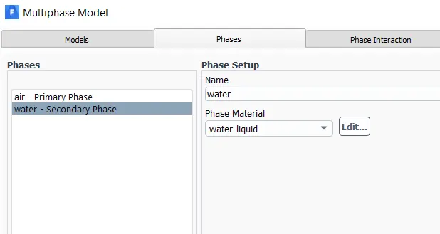
Air (lighter fluid) and water (denser fluid) were the two materials used to obtain the RT instability. Water was placed on top of air in the presence of gravity (g=9.81 m/s^2).
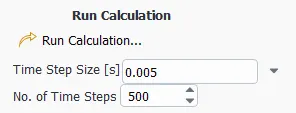
A transient simulation was carried out to observe the development of the instability with time.
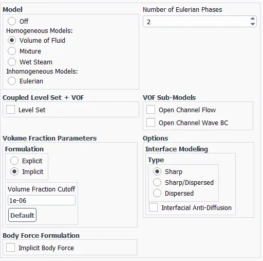
The Volume of Fluid method from the multiphase model with Implicit formulation was used to define 2 Eulerian phases.
Phases
Initialization and Patching
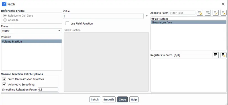
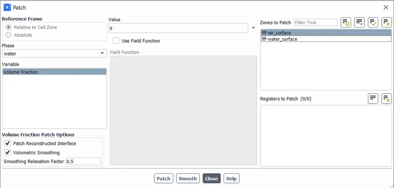
Solution
Residuals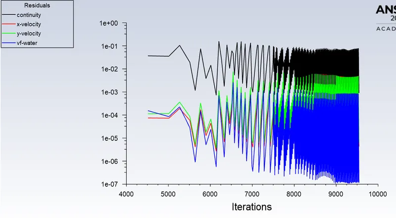
The contour for volume fraction of water was observed to analyze the RT instability. Solution animations were created for every case.
Animation:
Case 1 - 0.3mm element size
Residuals: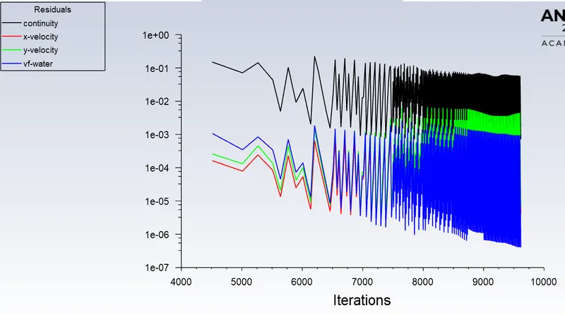
Animation:
Case 2 - 0.15mm element size
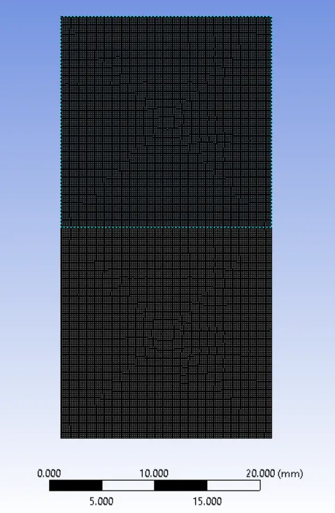
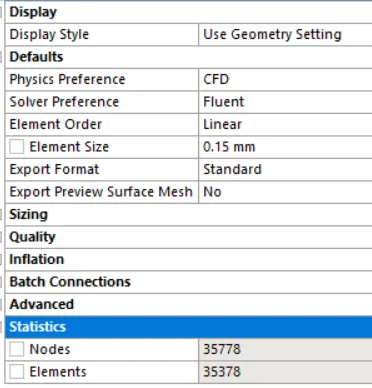
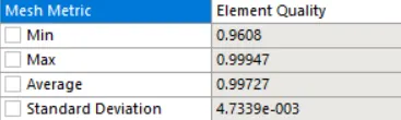
Residuals: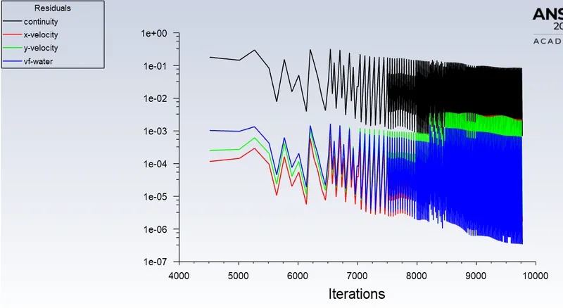
Animation:
Animations : Drive link - https://drive.google.com/drive/folders/15HNuVi9Ww8GEZCfvqU6EjcfFh5juiYDY?usp=sharing
Effect of mesh size on simulation -
As the mesh is made finer by reducing the element size, the instability is captured more accurately. Refining the mesh gives a smoother capture of the irregularities that take place at the interface of the two fluids. The diffusivity due to turbulent mixing is better captured by a finer mesh. Using finer mesh drastically increases the computational time.
Why steady state approach is not suitable?
In this particular project, the denser fluid is placed on top of the lighter fluid under the influence of gravity. Since the two fluids are immiscible, with time, the RT instability would be observed and ultimately, the denser fluid will completely settle at the bottom, with the lighter fluid on top of it. So, a steady state analysis would only interchange the position of the two fluids without giving and insight on how the change takes place.
The aim of this project is to observe and analyze "how" the Rayleigh-Taylor Instability develops with time. This is possible only by conducting a transient simulation.
Water and user defined fluid [density = 400 kg/m3, viscosity = 0.001 kg/m-s] [mesh - 0.1mm]
Residuals:
Animation:
Atwood number
As the RT instability develops, the initial perturbations progress from a linear growth phase into a non-linear growth phase, eventually developing "plumes" flowing upwards (in the gravitational buoyancy sense) and "spikes" falling downwards. In the linear phase, the fluid movement can be closely approximated by linear equations, and the amplitude of perturbations is growing exponentially with time. In the non-linear phase, perturbation amplitude is too large for a linear approximation, and non-linear equations are required to describe fluid motions. In general, the density disparity between the fluids determines the structure of the subsequent non-linear RT instability flows (assuming other variables such as surface tension and viscosity are negligible here).
The difference in the fluid densities divided by their sum is defined as the Atwood number, A.
The Atwood number (A) is a dimensionless number in fluid dynamics used in the study of hydrodynamic instabilities in density stratified flows. It is a dimensionless density ratio defined as
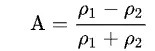
Where,  = density of heavier fluid ;
  = density of lighter fluid.
Atwood number is an important parameter in the study of Rayleigh–Taylor instability and Richtmyer–Meshkov instability. In Rayleigh–Taylor instability, the penetration distance of heavy fluid bubbles into the light fluid is a function of acceleration time scale, Agt^2, where g is the gravitational acceleration and t is the time.
For A close to 0, RT instability flows take the form of symmetric "fingers" of fluid; for A close to 1, the much lighter fluid "below" the heavier fluid takes the form of larger bubble-like plumes.
Atwood number calculation
A = (d1-d2)/(d1+d2)
Here, d1: density of heavier fluid ; d2: density of lighter fluid
- Case 1: Water and Air
d1= 998.2 kg/m^3 ; d2 = 1.225 kg/m^3
A = (d1-d2)/(d1+d2) = (998.2 - 1.225)/(998.2 + 1.225) = 0.998 - Case 2: Water and User defined fluid
d1=998.2 kg/m^3 ; d2 = 400 kg/m^3
A = (d1-d2)/(d1+d2) = (998.2 - 400)/(998.2 + 400) = 0.428
Comparison of 2 cases based on different Atwood number
The evolution of the RTI follows four main stages.
In the first stage, the perturbation amplitudes are small when compared to their wavelengths, the equations of motion can be linearized, resulting in exponential instability growth. In the early portion of this stage, a sinusoidal initial perturbation retains its sinusoidal shape.
In the second stage, non-linear effects begin to appear, one observes the beginnings of the formation of the ubiquitous mushroom-shaped spikes (fluid structures of heavy fluid growing into light fluid) and bubbles (fluid structures of light fluid growing into heavy fluid). The growth of the mushroom structures continues in the second stage and can be modeled using buoyancy drag models, resulting in a growth rate that is approximately constant in time. At this point, nonlinear terms in the equations of motion can no longer be ignored.
The spikes and bubbles then begin to interact with one another in the third stage. Bubble merging takes place, where the nonlinear interaction of mode coupling acts to combine smaller spikes and bubbles to produce larger ones. Also, bubble competition takes places, where spikes and bubbles of smaller wavelength that have become saturated are enveloped by larger ones that have not yet saturated. This eventually develops into a region of turbulent mixing, which is the fourth and final stage in the evolution. It is generally assumed that the mixing region that finally develops is self-similar and turbulent, provided that the Reynolds number is sufficiently large.
For low Atwood number, closer to 0, the bubble and mushroom-head shape was found to be relatively symmetrical in the linear stage. The disturbances and perturbations were linear for a longer period of time. Thus, symmetric "fingers" of the lighter fluid could be observed.
For high Atwood number, close to 1, the bubble and mushroom-head shape were not symmetrical/ less symmetrical. Large bubble-like plumes were observed, Also, the instability developed rapidly at an accelerating rate which leads to a non-linear growth rate.
Conclusion
A transient simulation is critical to analysis of the Rayleigh Taylor Instability.
A finer mesh captures the instability better.
For A close to 0, RT instability flows take the form of symmetric "fingers" of fluid; for A close to 1, the much lighter fluid "below" the heavier fluid takes the form of larger bubble-like plumes.