Week 5 Battery characteristics using drive cycle
In matlab there are two battery models for simulating the battery behaviour.
The models are shown below.
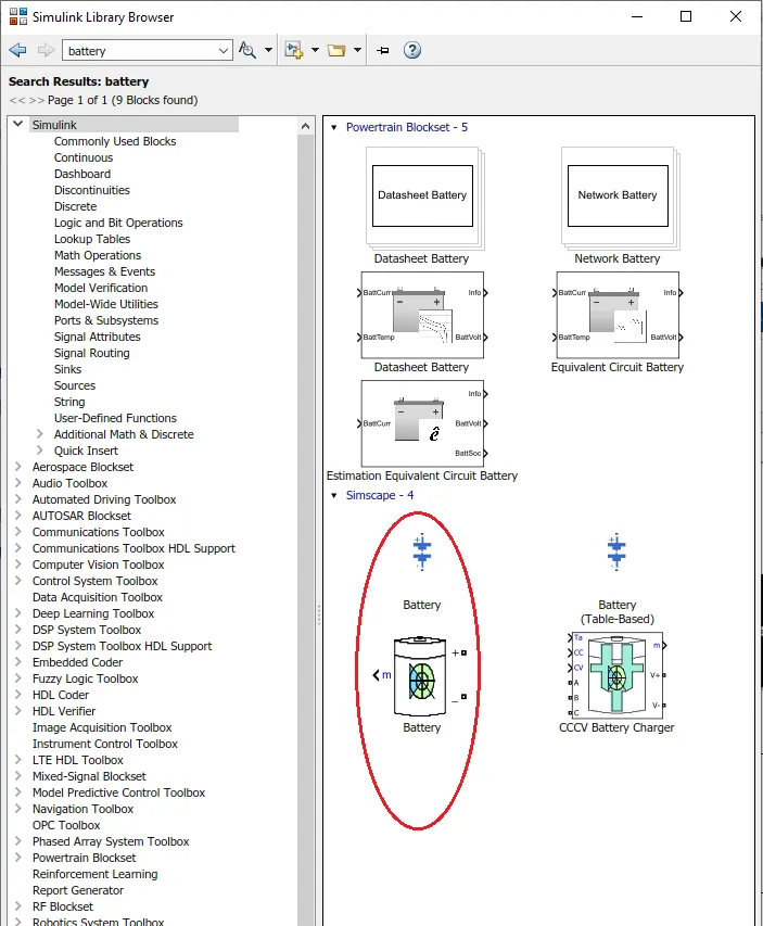
Generic Battery Model:
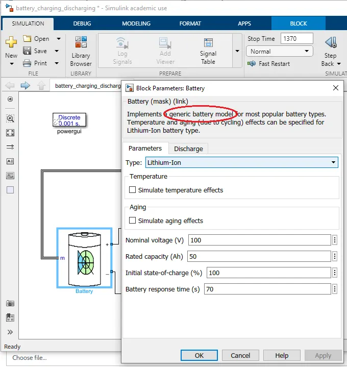
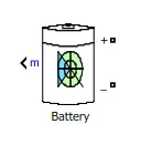
In generic model, two input parameters, one output parameter ""m" measurement port, which has voltage, SOC and Current of the generic battery.
The aim of the challenge is simulate the generic battry model charge discharge using UDDS data.
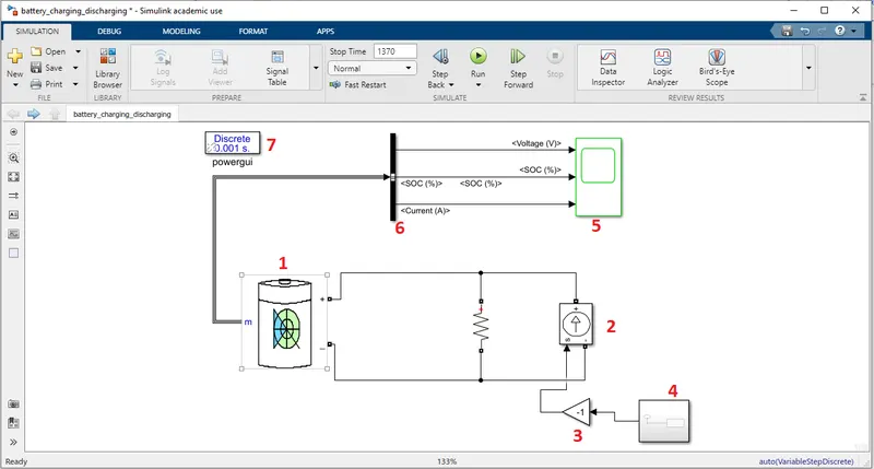
The circuit for charge and discharge of UDDS data is shown in the following figure
The blocks which are used for connecting the charge discharge circuit is given as follows
1. Generic Battery model
2. COntrolled current source
3. Gain
4. Signal Builider for UDDS
5. Scope
6. Bus selector
7. powergui
Results
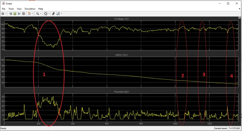
The reults have three subplots, which are
1. Voltage
2. SoC
3. Current
The results are divided into four divisons
1.The voltage discharges, between 200 sec to 350 sec which has peak current in UDDS. and SOC also deteriates at these time interval.
2. The Voltage raises at rest position of UDDS
4. The voltage discharges and charges at UDDS 1300 sec
Circuit working:
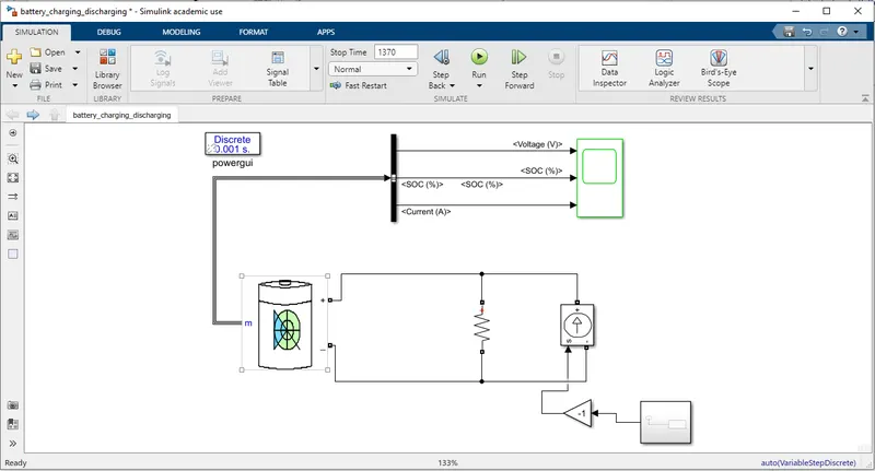
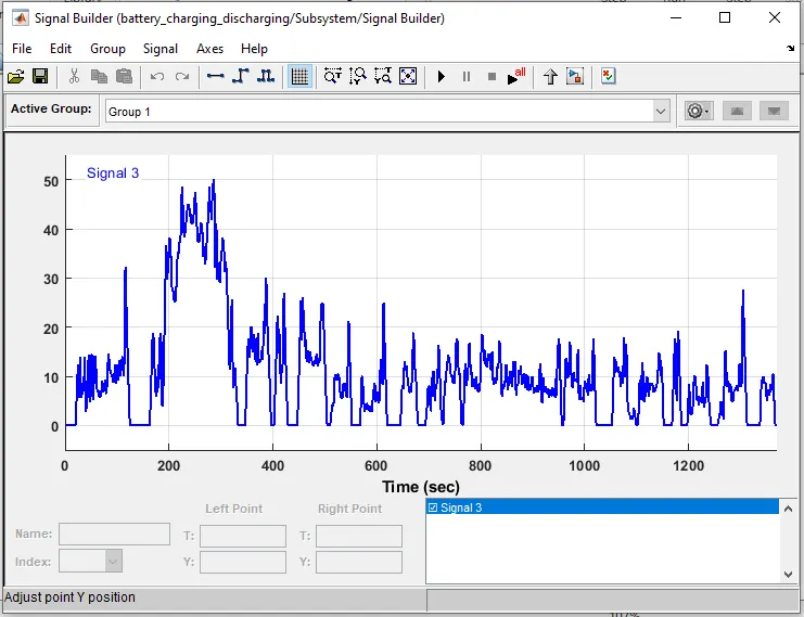
The cirucit is connected as follows. The current equivalent of UDDS is developed with signal builder. The signal builder is shown below.
The discharge current given to the battery need to be negative so gain block is used to invert the current. Controlled current source is connected to the battery which is controlled through signal builder. The effect of the UDDS to the battery is measured through measurment block. m, which is measured voltage, SoC and Current. the measuremnt block is connected to the scope via bus selector. The bus selector selects its three input signals to scope.
II. The same circuit can be modeled with another battery model.
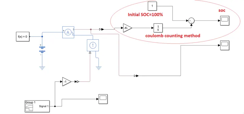
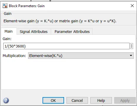
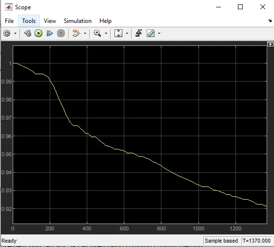
This model does not have measurement port, so SOC is calculted using coulomb couting method. Signal builder is same as signal bulider is shown above. SOC is given as follows.
Conclusion:
- The screen shot of the circuit and results is given.
- The analysis of the results, which are soc, current and voltage are explained.
- The circuit working is explained with respecitve blocks which are used in the circuit.
- The another model of the battery is used to design the same circuit. The coulomb counting method is used to measure the SOC as the physical battery model does not have measurement port.