Week 5.3 - Forced convection Analysis
Theory:
Forced convection is a mechanism or type of transport, in which fluid motion is generated by an external source (like a pump, fan, suction device, etc.). Alongside natural convection, thermal radiation, and thermal conduction it is one of the methods of heat transfer and allows significant amounts of heat energy to be transported very efficiently. Natural convection can create a noticeable difference in temperature within a home. Often this becomes places where certain parts of the house are warmer and certain parts are cooler. Forced convection creates a more uniform and therefore comfortable temperature throughout the entire home. This reduces cold spots in the house, reducing the need to crank the thermostat to a higher temperature, or put on sweaters. The total no of bodies in the CAD model is calculated into icepack primitive objects in space claim and modify the components in icepack modules and define the correct physics. The total no of bodies in the CAD model is calculated. Depending on the functionalities of the individual bodies or groups of bodies are segregated.
Types of bodies.
- Focus bodies: the body which emits some heat or obstructs the flow of the system.
- Necessary bodies: the bodies which will have an effect on the focus bodies.
- Peripheral bodies: the bodies may or may not have an effect on the focus bodies.
- Dispensable bodies: the small bodies which have no effect on the physics of the system.
Geometry
Geometry simplification deals with the generation of geometric models that resemble the input. model but involve fewer faces, edges, and vertices. The level of Detail is concerned with the possibility of using different representations of a geometric object having different levels of accuracy and complexity.
Mostly Using Command
- Fill
- Pull
- Remove Curves, Faces, etc
- Combine and Split Body
- Icepak Simplify
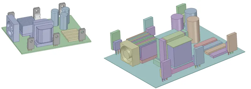
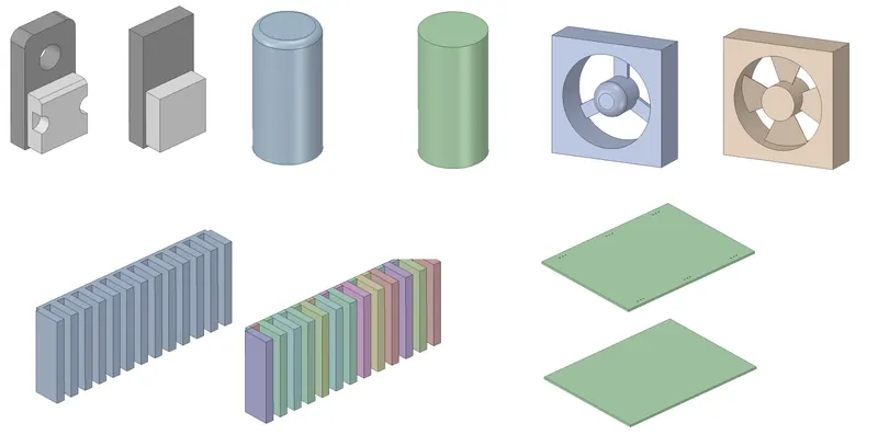
The following steps are used to simplify the given CAD model into an Icepak model
- The "Identify Objects" command is used to simplify various objects in the model. The image attached below shows (in red color) the objects identified for simplification.
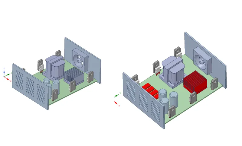
- The base of the housing is split further in order to separate the PCB supports from the housing.
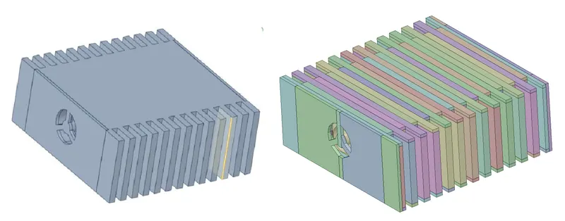
- The fan in the model is simplified using the "Fan" command. The images attached below show the fan before and after simplification.
Model Check
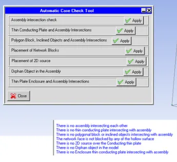
Macros --> Productivity --> Validation --> Automatic case check tool - It checks the assembly interface between the various objects and assembly.
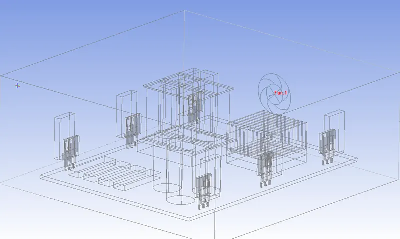
The images attached below show the model in the Icepak graphics window.
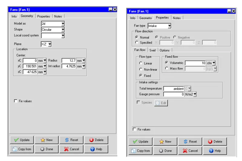
In order to simplify the model even further, the 3-D fan imported from ANSYS SpaceClaim is replaced with a 2-D Icepak fan which serves the same purpose. The image attached below shows the settings applied in the "Geometry" tab to define the fan
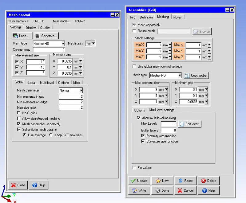
In order to reduce the overall mesh count by preventing mesh bleeding, a non-conformal meshing technique is applied. Assemblies are defined around key objects that affect the flow and/or temperature field. The image attached below shows the assemblies with appropriate slack settings.
Meshing
All the assemblies shown above employ the global mesh control settings except the assembly defined around the CAD object "Coil". In order to capture the geometry of the CAD object ("Coil") accurately the following settings are applied for the mesh within the assembly:
Mesh type: Mesher-HD
- Max element size
- X: 1.5 mm
- Y: 1.5 mm
- Z: 0.5 mm
- Set uniform mesh params: Enabled
- Use average: Enabled
- Allow multi-level meshing: Enabled
- Max Levels: 2
The computational domain is discretized using Hexa unstructured mesh with the following settings:
Max element size
- X: 10mm
- Y: 10mm
- Z: 5mm
- Mesh parameters: Normal
- Min elements in the gap: 2
- Min elements on edge: 2
- Max size ratio: 2
- Mesh assemblies separately: Enabled
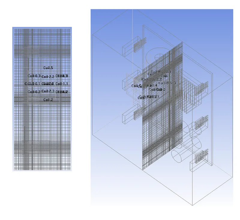
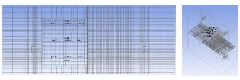
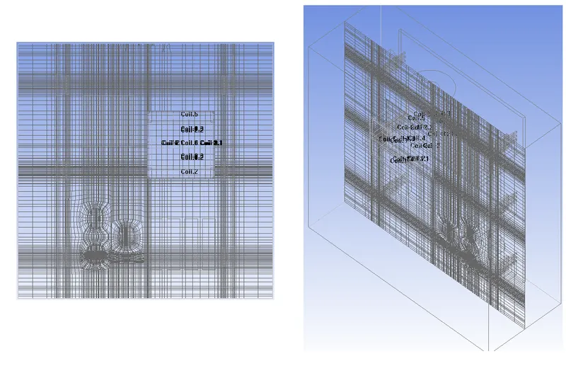
For the current model, the mesh is locally refined within the objects "BGA" and "BGA-Heat-Sink", and the assembly is defined around the CAD object "Coil" using per-object meshing parameters. The generated mesh yields 390125 elements and 455388 nodes. The images attached below show the computational mesh along different planes.
Mesh on Plane X
Mesh on Plane Y
Mesh on Plane Z
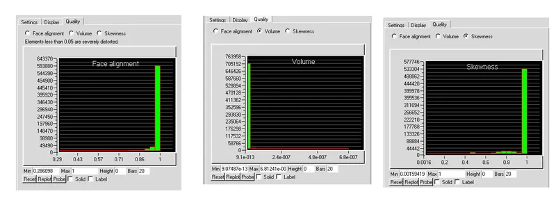
Mesh Quality
Face alignment
The face alignment is a measure of mesh quality defined by the face-alignment index bar (C0.C1).bar(f)
- Where C0 and C1 are the centroids of the two adjacent elements and are the normal vector to the face between the two elements.
- Range from 0 (bad) to 1 (good).
- Face alignment >0.1 (preferred), >0.5 (must), 0.15> (best).
Volume:
- Volume is, the preferable volume of mesh to be greater than 1e-13 for a single-precision solver.
- Volume >1e-15 for double precision solver as long as the total magnitude of the model is <12(i.e. 1e-15 - 1e-13).
- Max/min cell volume should be <10^7 for a single-precision solver.
Skewness
- It is one of the primary quality measures for a mesh. According to the definition of skewness, a value of 0 indicates an equilateral cell (best) and a value of 1 indicates a completely degenerate cell (worst).
- Skewness is defined as the difference between the shape of the cell and the shape of an equilateral cell of equivalent volume.
- A general rule is that the maximum skewness for a triangular/tetrahedral mesh in most flows should be kept below 0.95, with an average value that is less than 0.33.
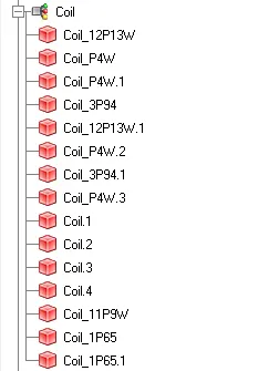
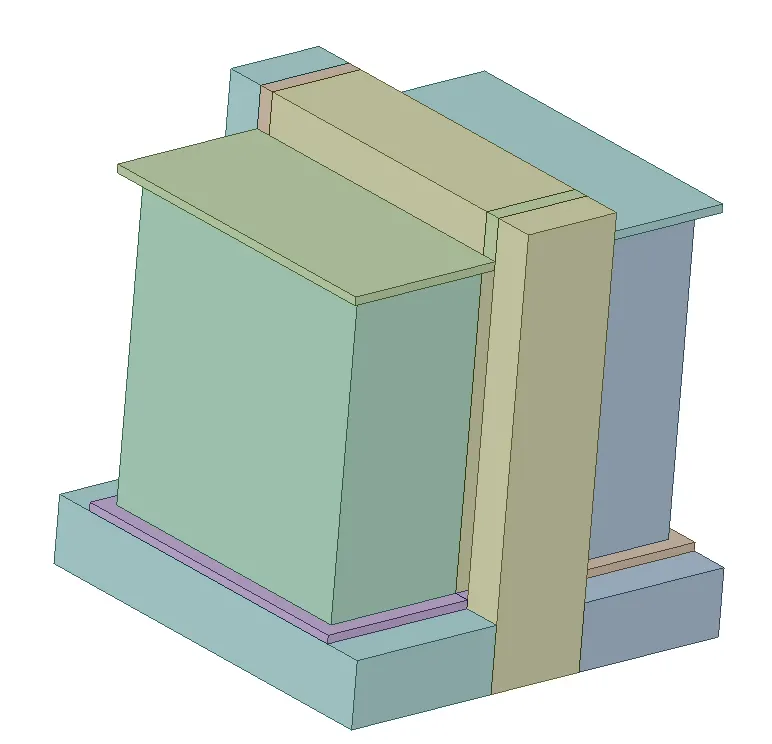
Heat source Calculation for Transformer (Heat Coil)
Residuals
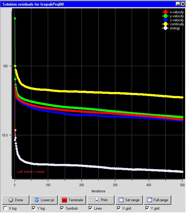
the residual measures the local imbalance of a conserved variable in each control volume. Therefore, every cell in your model will have its own residual value for each of the equations being solved. In an iterative numerical solution, the residual will never be exactly zero. The residuals for the following equations are plotted against the number of iterations:
- Continuity equation.
- X-momentum equation.
- Y-momentum equation.
- Z-momentum equation.
- Energy equation.
Solver
The three-dimensional steady-state Navier-Stokes equations for the model are solved within the computational domain for flow and temperature fields, using the Fluent solver available in ANSYS Icepak. The following settings are applied to the solver:
- Variables solved: Flow (velocity, pressure) and Temperature
- Radiation: Off
- Flow regime: Turbulent (Zero equation)
- Time variation: Steady
- Solution initialization
- X velocity: 0
- Y velocity: 0
- Z velocity: 0
- Temperature: ambient (20 deg. C)
- Number of iterations: 200
- Convergence criteria
- Flow: 1e-6
- Energy: 1e-7
- Joule heating: 1e-7
- Configuration: Parallel
- Number of processors: 4
- GPU computing: Enabled
- Number of GPUs: 2
- Precision: Double
The BGA and six die in the model are assigned a total constant power of 30 W and 2.5 W each, respectively. Hence the total power generated by the model is 45 W. The fan is assigned a fixed volumetric flow rate of 10 CFM.
Solution
Mass flow rates: Specified Calculated
--------- ----------
Grille n/a -0.00413198 kg/s
Fan.1 0.0054812 kg/s 0.00413185 kg/s
Volume flow rates: Specified Calculated
--------- ----------
Grille n/a -0.00355776 m3/s
Fan.1 10 cfm 0.00355765 m3/s
Heat flows for objects with power specified:
Object Specified Calculated
Capacitor.1 5 W 4.9965 W
Capacitor.2 5 W 4.99691 W
Capacitor.3 5 W 5.00198 W
Coil-0 50 W 50.0002 W
Coil-0.1 50 W 50.0001 W
Coil-0.2 50 W 50.0017 W
Coil-0.3 50 W 50.0018 W
Coil-1 50 W 50.0002 W
Coil-1.1 50 W 50.0001 W
Coil-1.2 50 W 50.0017 W
Coil-1.3 50 W 50.0018 W
Coil-2 50 W 50.0031 W
Coil-2.1 50 W 50.003 W
Coil-2.2 50 W 50.0215 W
Coil-2.3 50 W 50.0214 W
Coil.1 50 W 50.001 W
Coil.2 50 W 50.0041 W
Coil.3 50 W 50.0009 W
Coil.4 50 W 50.0029 W
Coil.5 50 W 50.0019 W
Coil.6 50 W 50.0086 W
BGA 25 W 24.9967 W
Heat flows for openings, walls, grilles, and fans:
Grille -940.005 W
Fan.1 -0.145068 W
Maximum temperatures:
Capacitor.1 709.047 C
Capacitor.2 754.707 C
Capacitor.3 741.083 C
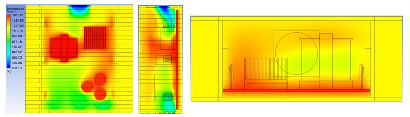
Coil-0 1174.83 C
Coil-0.1 1184.47 C
Coil-0.2 1183.47 C
Coil-0.3 1183.56 C
Coil-1 1248.05 C
Coil-1.1 1239.64 C
Coil-1.2 1245.92 C
Coil-1.3 1245.65 C
Coil-2 1235.41 C
Coil-2.1 1243 C
Coil-2.2 1240.73 C
Coil-2.3 1241.02 C
Coil.1 1237.35 C
Coil.2 1237.35 C
Coil.3 1232.43 C
Coil.4 1233.8 C
Coil.5 1227.07 C
Coil.6 1182.98 C
Component.1 830.842 C
Component.2 855.502 C
Component.3 875.004 C
Component.4 888.441 C
DIE_AF0 340.04 C
DIE_AF0.1 329.515 C
DIE_AF0.2 350.037 C
DIE_AF0.3 343.941 C
DIE_AF0.4 352.903 C
DIE_AF0.5 354.82 C
HS_AF0.1 341.021 C
HS_AF0.2 330.733 C
HS_AF0.3 350.456 C
HS_AF0.4 345.159 C
HS_AF0.5 353.269 C
HS_AF0.6 355.117 C
LEAD_1_AF01 809.51 C
LEAD_1_AF01.1 676.449 C
LEAD_1_AF01.2 814.52 C
LEAD_1_AF01.3 679.594 C
LEAD_1_AF01.4 821.628 C
LEAD_1_AF01.5 684.163 C
LEAD_1_AF01.6 1071.54 C
LEAD_1_AF01.7 751.287 C
LEAD_1_AF01.8 1088.32 C
LEAD_1_AF01.9 766.436 C
LEAD_1_AF01.10 1103.04 C
LEAD_1_AF01.11 774 C
LEAD_1_AF01.12 1015.29 C
LEAD_1_AF01.13 806.235 C
LEAD_1_AF01.14 1001.49 C
LEAD_1_AF01.15 805.562 C
LEAD_1_AF01.16 992.86 C
LEAD_1_AF01.17 806.004 C
T0220_Case 731.245 C
T0220_Case.1 736.99 C
T0220_Case.2 731.93 C
T0220_Case.3 731.766 C
T0220_Case.4 739.308 C
T0220_Case.5 738.381 C
T0220_Case.6 739.143 C
T0220_Case.7 739.303 C
T0220_Case.8 597.434 C
T0220_Case.9 604.341 C
T0220_Case.10 597.498 C
T0220_Case.11 604.584 C
T0220_Case.12 597.266 C
T0220_Case.13 604.22 C
T0220_Case.14 603.104 C
T0220_Case.15 604.55 C
T0220_Case.16 964.53 C
T0220_Case.17 973.24 C
T0220_Case.18 965.394 C
T0220_Case.19 965.296 C
T0220_Case.20 974.394 C
T0220_Case.21 973.903 C
T0220_Case.22 972.776 C
T0220_Case.23 974.187 C
T0220_Case.24 672.383 C
T0220_Case.25 680.453 C
T0220_Case.26 672.101 C
T0220_Case.27 680.351 C
T0220_Case.28 671.33 C
T0220_Case.29 677.679 C
T0220_Case.30 679.675 C
T0220_Case.31 680.509 C
T0220_Case.32 806.78 C
T0220_Case.33 821.27 C
T0220_Case.34 807.634 C
T0220_Case.35 821.942 C
T0220_Case.36 807.731 C
T0220_Case.37 821.194 C
T0220_Case.38 821.626 C
T0220_Case.39 821.887 C
T0220_Case.40 742.952 C
T0220_Case.41 748.117 C
T0220_Case.42 743.536 C
T0220_Case.43 749.152 C
T0220_Case.44 743.695 C
T0220_Case.45 749.616 C
T0220_Case.46 746.95 C
T0220_Case.47 747.328 C
BGA 936.543 C
BGA-Heat-Sink 878.667 C
Front-Panel 356.335 C
Front-Panel.1 345.508 C
Front-Panel.2 356.359 C
Front-Panel.3 356.398 C
Housing.1 349.829 C
Housing.2 337.656 C
Housing.3 326.79 C
Housing.4 354.226 C
Housing.5 355.959 C
Housing.6 350.097 C
Housing.7 344.099 C
Housing.8 328.155 C
Housing.9 327.152 C
Housing.10 330.648 C
Housing.11 329.139 C
Housing.12 333.674 C
Housing.13 340.656 C
Housing.14 342.435 C
Housing.15 337.112 C
Housing.16 338.947 C
Housing.17 335.544 C
Housing.18 331.874 C
Housing.19 347.257 C
Housing.20 345.656 C
Housing.21 348.494 C
Housing.22 352.565 C
Housing.23 351.382 C
Housing.24 354.488 C
Housing.25 356.103 C
Housing.26 355.668 C
Housing.27 355.94 C
Housing.28 355.084 C
Housing.29 356.064 C
Housing.30 353.591 C
Housing.31 343.259 C
Housing.32 338.847 C
Housing.33 337.975 C
Housing.34 340.902 C
Housing.35 339.717 C
Housing.36 341.888 C
Housing.37 345.815 C
Housing.38 354.587 C
Housing.39 353.139 C
Housing.40 354.737 C
Housing.41 353.972 C
Housing.42 354.531 C
Housing.43 354.179 C
Housing.44 354.611 C
Housing.45 353.488 C
Housing.46 354.665 C
Housing.47 351.947 C
Housing.48 352.542 C
Housing.49 350.334 C
Housing.50 351.085 C
Housing.51 348.217 C
Housing.52 346.954 C
Housing.53 349.33 C
Housing.54 354.441 C
Housing.55 344.459 C
Housing.56 355.311 C
Housing.57 357.596 C
Housing.58 358.025 C
Housing.59 357.929 C
Housing.60 357.851 C
Housing.61 358.016 C
Housing.62 356.909 C
Housing.63 357.475 C
Housing.64 356.18 C
Housing.65 356.865 C
Housing.66 351.015 C
Housing.67 348.63 C
Housing.68 349.836 C
Housing.69 346.158 C
Housing.70 347.4 C
Housing.71 353.282 C
Housing.72 352.164 C
Housing.73 354.337 C
Housing.74 343.697 C
Housing.75 344.916 C
Housing.76 339.471 C
Housing.77 338.692 C
Housing.78 341.413 C
Housing.79 342.522 C
Housing.80 340.389 C
Housing.81 347.957 C
Housing.82 346.546 C
Housing.83 348.515 C
Housing.84 345.397 C
Housing.85 347 C
Housing.86 342.765 C
Housing.87 345.062 C
Housing.88 340.478 C
Housing.89 342.772 C
Housing.90 338.259 C
Housing.91 336.209 C
Housing.92 334.119 C
Housing.93 335.883 C
Housing.94 337.94 C
Housing.95 340.32 C
Housing.96 334.096 C
Housing.97 350.685 C
Housing.98 352.456 C
Housing.99 353.345 C
Housing.100 354.205 C
Housing.101 353.704 C
Housing.102 352.295 C
Housing.103 349.164 C
Housing.104 350.717 C
Rear-Panel 320.975 C
Rear-Panel.1 327.411 C
Rear-Panel.2 335.35 C
Rear-Panel.3 324.913 C
Rear-Panel.4 367.83 C
Rear-Panel.5 328.051 C
Rear-Panel.6 326.393 C
Rear-Panel.7 375.942 C
Rear-Panel.8 341.865 C
Rear-Panel.9 322.58 C
Rear-Panel.10 329.382 C
Rear-Panel.11 325.29 C
Rear-Panel.12 366.458 C
Rear-Panel.13 324.991 C
Rear-Panel.14 331.735 C
Rear-Panel.15 325.734 C
Rear-Panel.16 325.052 C
Rear-Panel.17 320.072 C
Rear-Panel.18 324.4 C
Rear-Panel.19 334.201 C
Rear-Panel.20 333.764 C
Rear-Panel.21 321.007 C
Rear-Panel.22 325.627 C
Rear-Panel.23 324.279 C
Rear-Panel.24 334.757 C
Rear-Panel.25 320.106 C
Rear-Panel.26 325.899 C
Rear-Panel.27 324.619 C
Rear-Panel.28 373.909 C
Rear-Panel.29 355.594 C
Rear-Panel.30 376.154 C
Rear-Panel.31 337.922 C
Rear-Panel.32 333.924 C
Rear-Panel.33 333.626 C
Rear-Panel.34 334.418 C
Rear-Panel.35 334.957 C
PWB 1168.17 C
Overall totals:
power 940.068 W
mass flow through boundaries -1.3e-007 kg/s
volume flow through boundaries -1.12e-007 m3/s
Post-Processing
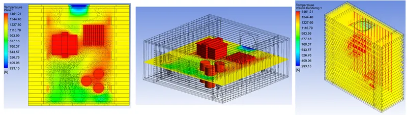
- Temperature Contours
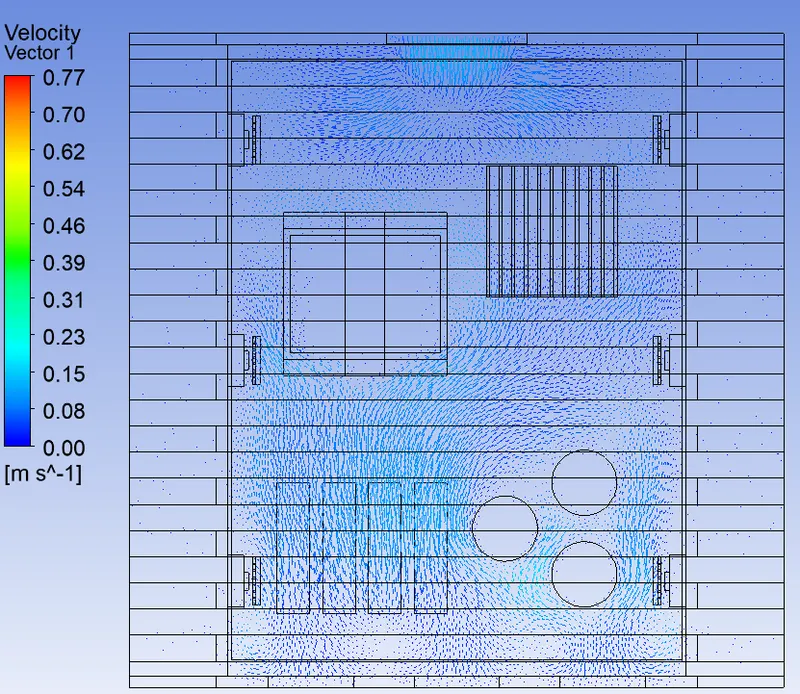
- Velocity Contours
Conclusion
In the current project, the given CAD model of an electronic enclosure assembly was simplified into an Icepak model using the commands available in ANSYS SpaceClaim. The model was imported into ANSYS Icepak by creating a suitable workflow in ANSYS Workbench. The model was meshed using a non-conformal meshing technique and steady-state simulation was performed with appropriate solver settings. The following conclusions can be drawn from the simulation results:
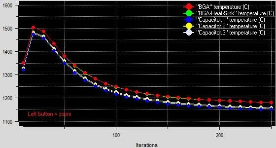
- Both the residual plot and the temperature monitor plot indicated that the solution reached a steady-state after 100 iterations.