Week 5.1 - Non-Conformal Meshing and Solving a Cold plate model
Objective:- Perform Computational analysis for the Cold plate and also create the non-conformal mesh for the model.
TASK
- Create non-conformal mesh assembly.
- Solve for Flow and Temperature model & choose zero equation turbulent model and setup gravity vector.
- Setup transient simulation with an initial velocity of 0.005 m /s in antigravity direction and create monitor points.
- Post-process the results using the Plane cut, Vector plot, Temperature contour, and object face
Steps for Performing Analysis
1. Cabinet
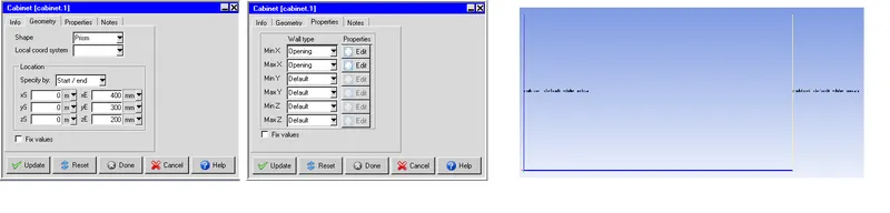
The “Cabinet” is said to define the flow domain of interest in Icepak but it may not be the case with every geometry that the fluid domain is simply a cuboid that can be realized just merely by resizing the cabinet.
i) Geometry Shape - Prism.
Specified By - Start/end.
- Start Xs - 0 End Xe - 400 mm.
- Start Ys - 0 End Ye - 300mm.
- Start Zs - 0 End Ze - 200mm.
ii) Properties - The wall type for the cabinet is defined.
- Min X - Opening Max X - Opening
- Min Y - Default Max Y - Default
- Min Z - Default Max Z - Default
2. Geometry Solid-Block
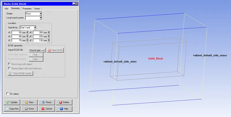
Shape - Prism.
Specified By - Start/end.
- Start Xs - 50 mm. End Xe - 350 mm.
Start Ys - 80 mm. End Ye - 220mm.
Start Zs - 70 mm. End Ze - 130mm.
ii) Properties
- Block type - Solid.
- Solid Material - Default.
3 Geometry - Fluid Domain
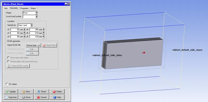
Shape - Prism.
Specified By - Start/end.
- Start Xs - 60 mm. End Xe - 340 mm.
- Start Ys - 90 mm. End Ye - 210mm.
- Start Zs - 80 mm. End Ze - 120mm.
ii) Properties
- Block type - Fluid.
- Fluid Material - Water.
4. Geometry - Heated Plate 1
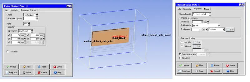
Shape - Rectangular.
Plane - X-Y.
Specified By - Start/end.
- Start Xs - 70 mm. End Xe - 330 mm.
- Start Ys - 100 mm. End Ye - 200mm.
- Start Zs - 60 mm.
ii) Properties
- Thermal model - Conducting thick.
- Thickness - 10mm.
- Solid Material - Default.
- Total power - 200W
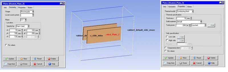
5. Geometry - Heated Plate 2
Shape - Rectangular.
Plane - X-Y.
Specified By - Start/end.
- Start Xs - 70 mm. End Xe - 330 mm.
- Start Ys - 100 mm. End Ye - 200mm.
- Start Zs - 60 mm.
ii) Properties
- Thermal model - Conducting thick.
- Thickness - 10mm.
- Solid Material - Default.
- Total power - 200W
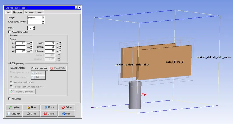
6 Geometry - Inlet Pipe
Shape - Cylinder.
Plane - X-Z.
- Center xC - 100 mm.
- Center yC - 0 mm.
- Center zC - 100 mm.
- Height - 90mm.
- Radius - 20mm.
- Int Radius - 15mm.
ii) Properties
- Block type - Solid.
- Solid Material - Default.
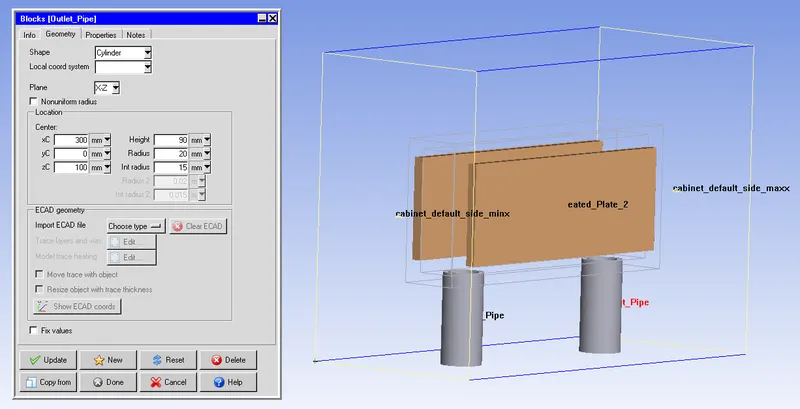
7 Geometry - Outlet Pipe
Shape - Cylinder.
Plane - X-Z.
- Center xC - 300 mm.
- Center yC - 0 mm.
- Center zC - 100 mm.
- Height - 90mm.
- Radius - 20mm.
- Int Radius - 15mm.
ii) Properties
- Block type - Solid.
- Solid Material - Default.
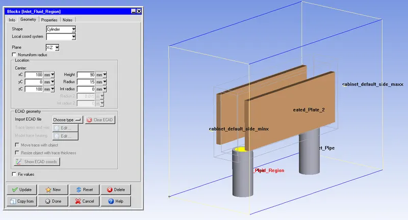
8 Geometry - Inlet Fluid region
Shape - Cylinder.
Plane - X-Z.
- Center xC - 100 mm.
- Center yC - 0 mm.
- Center zC - 100 mm.
- Height - 90mm.
- Radius - 15mm.
ii) Properties
- Block type - Fluid.
- Fluid Material - Water.
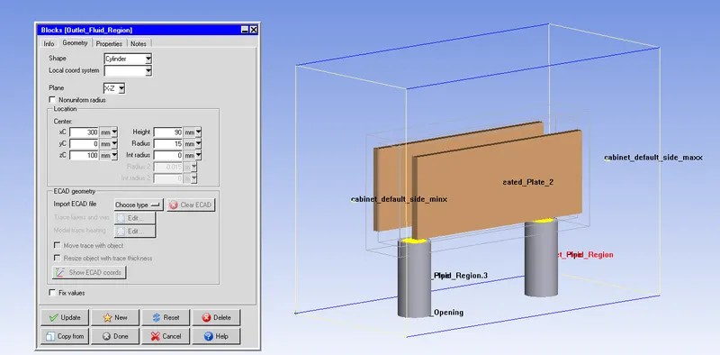
9 Geometry - Outlet Fluid region
Shape - Cylinder.
Plane - X-Z.
- Center xC - 300 mm.
- Center yC - 0 mm.
- Center zC - 100 mm.
- Height - 90mm.
- Radius - 15mm.
ii) Properties
- Block type - Fluid.
- Fluid Material - Water.
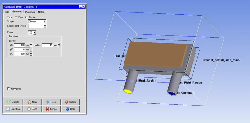
10 Boundary - Inlet Opening
Shape - Cylinder.
Plane - X-Z.
- Center xC - 100 mm.
- Center yC - 0 mm.
- Center zC - 100 mm.
- Radius - 15mm.
ii) Properties
- Temperature - Ambient
- Velocity - y - 0.2m/s
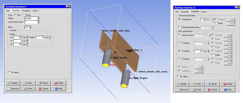
10 Boundary - Outlet Opening
Shape - Cylinder.
Plane - X-Z.
- Center xC - 100 mm.
- Center yC - 0 mm.
- Center zC - 100 mm.
- Radius - 15mm.
ii) Properties
- Temperature - Ambient
- Velocity - y - 0.2m/s
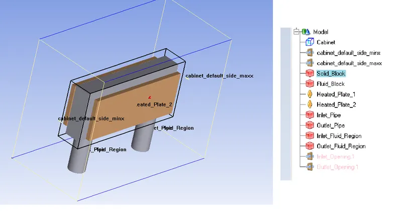
11 Final Model
Meshing
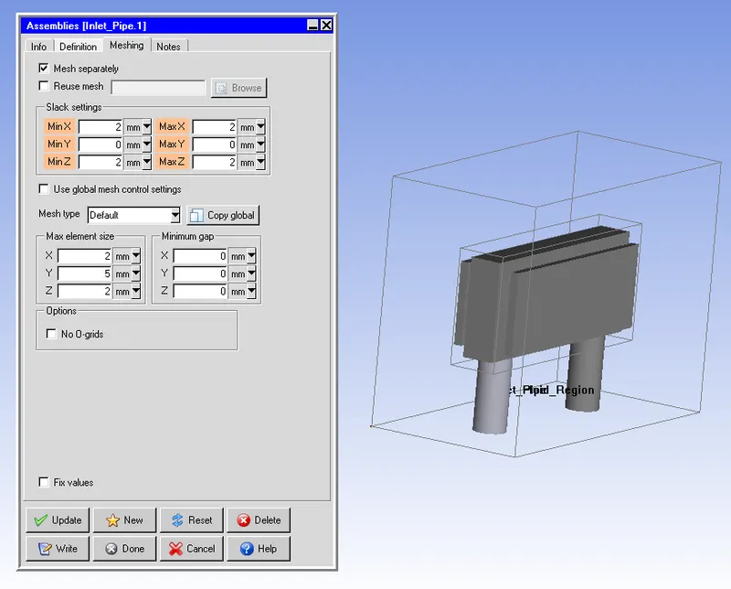
A. Assemble - 1 Inlet
Select inlet pipe, inlet fluid region, and inlet opening create --> assembly.
Under the meshing tab choose Mesh separately,
i) Slack setting
- Min X - 2 mm. Max X - 2 mm.
- Min Y - 0. Max Y - 0.
- Min Z - 2mm. Max Z - 2mm.
ii) Mesh type
- Max element size X - 2mm.
- Max element size Y - 5mm.
- Max element size Z - 2mm.
- Min Gap X - 0.02 mm.
- Min Gap Y - 0.05 mm.
- Min Gap Z - 0.02 mm
B. Assemble - 2 Outlet
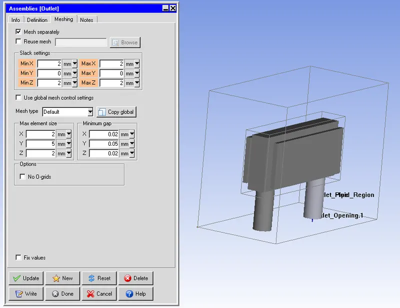
Select outlet pipe, outlet fluid region, and outlet opening create --> assembly.
Under the meshing tab choose Mesh separately,
i) Slack setting
- Min X - 2 mm. Max X - 2 mm.
- Min Y - 0. Max Y - 0.
- Min Z - 2mm. Max Z - 2mm.
ii) Mesh type
- Max element size X - 2mm.
- Max element size Y - 5mm.
- Max element size Z - 2mm.
- Min Gap X - 0.02 mm.
- Min Gap Y - 0.05 mm.
- Min Gap Z - 0.02 mm
C Assemble - 3 - Complete Domain
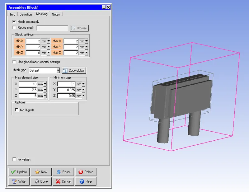
Select solid block, Fluid Block, heated plate 1,heated plate 2, assemble 1 & assemble 2, create --> assemble.
Under the meshing tab choose Mesh separately,
i) Slack setting
- Min X - 2 mm. Max X - 2 mm.
- Min Y - 0. Max Y - 2 mm.
- Min Z - 2mm. Max Z - 2mm.
ii) Mesh type
- Max element size X - 10mm.
- Max element size Y - 7.5mm.
- Max element size Z - 5mm.
- Min Gap X - 0.1 mm.
- Min Gap Y - 0.075 mm.
- Min Gap Z - 0.05 mm
Model Check
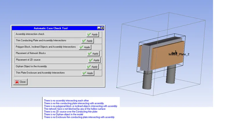
Macros --> Productivity --> Validation --> Automatic case check tool - It checks the assembly interface between the various objects and assembly.
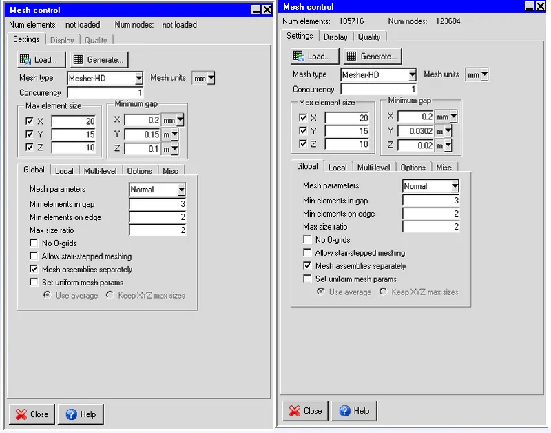
Mesh Control
ii) Mesh type - Mesher -HD
- Max element size X - 20mm.
- Max element size Y - 15mm.
- Max element size Z - 10mm.
- Min Gap X - 0.2 mm.
- Min Gap Y - 0.15 mm.
- Min Gap Z - 0.1 mm
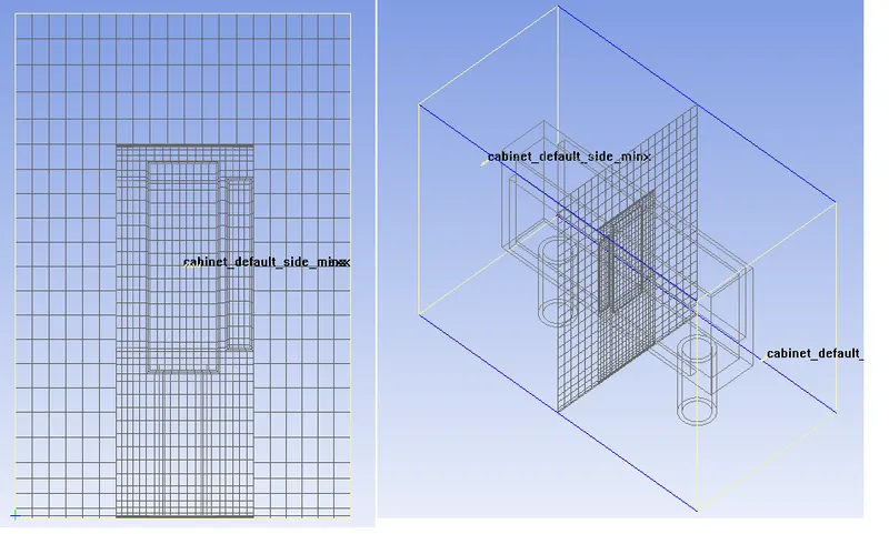
Mesh View - X Plane
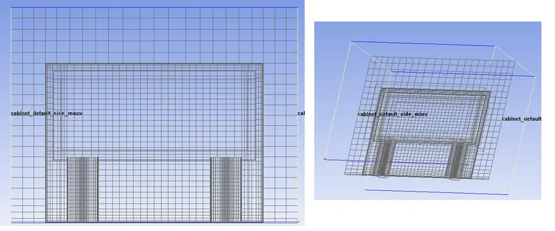
Mesh View - Y Plane
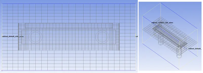
Mesh View - Z Plane
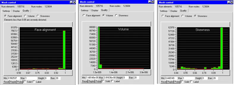
Mesh Verification
Face alignment
- It is the measure of mesh quality defined by face alignment index = C0C1.
- f C0 & C1 are the centroids of two adjacent elements that are normal vectors to the face between the two elements.
- Range of face alignment 0 (bad) to 1 (good) & value greater than 0.1 (preferred) & value greater than 0.15 provide better results.
Volume
- The preferable volume of mesh to be greater than 1e-13 for single-precision solver & greater than 1e-15 for double precision.
- Max / Min cell volume should be less than 10^7 for single-precision & must be less than 10^12 for double-precision since very small volumes create a divergence in the solution.
Skewness
- It determines how close to the ideal & is based on the equilateral volume. A value greater than 0.5 provides good cell quality
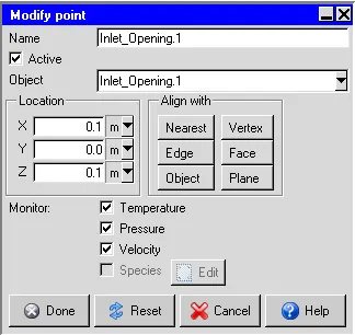
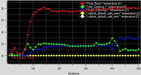
Monitor Points
Solver
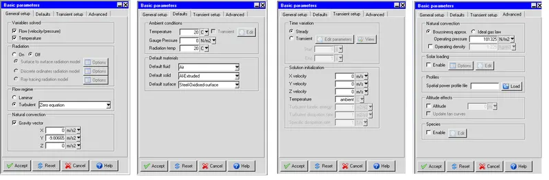
The three-dimensional steady-state Navier stokes equations for the model are solved within the computational domain.
General Setup
- Variables solved - flow and temperature.
- Radiation - Off.
- Flow regime - Turbulent - The zero equations are solved for the turbulent model.
- Natural convection is considered for this model.
- The gravity vector for the y axis is set to -9.81 m/s2.
The default value of the parameters is set to default.
- Transient Setup
- Time variation - Steady
- Solution Initialization
- X velocity - 0.
- Y velocity - 0.005 m/s.
- Z velocity -0.
- Temperature - ambient.
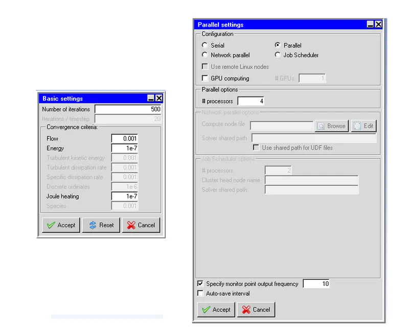
Basic settings
- No of iterations - 500.
- Convergence criteria
- Flow - 0.001.
- Energy - 1e-7.
- Joule heating - 1e-7.
Parallel Settings
- Configuration - parallel.
- Parallel options - 4 processors.
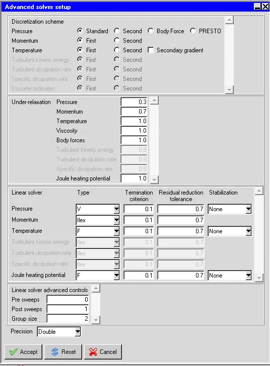
Advance Solver Setup
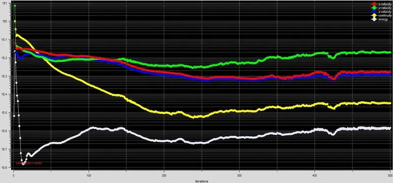
Residuals
the residual measures the local imbalance of a conserved variable in each control volume. Therefore, every cell in your model will have its own residual value for each of the equations being solved. In an iterative numerical solution, the residual will never be exactly zero. The residuals for the following equations are plotted against the number of iterations:
- Continuity equation.
- X-momentum equation.
- Y-momentum equation.
- Z-momentum equation.
- Energy equation.
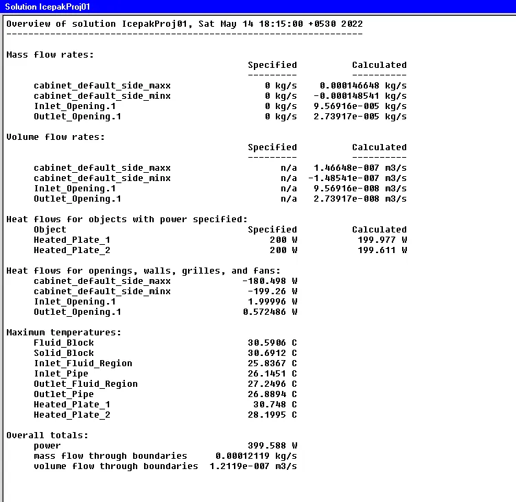
Solution
Post-Processing
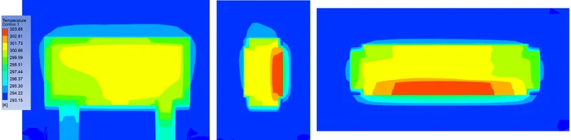
Temperature Contours
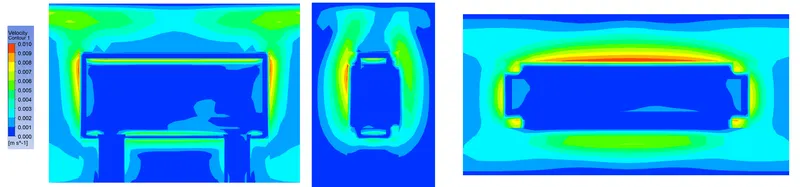
Velocity Contours
Conclusion
In this project, the given model of the cold plate was meshed using ANSYS Icepak using the non-conformal meshing, per-object meshing parameters, and multi-level meshing. The three-dimensional steady-state governing equations for the model were solved for flow and temperature within the computational domain in the Icepak.
- The maximum temperature within the computational domain is 30.75 deg.C.
- The maximum air velocity within the computational domain is 0.238 m/s.