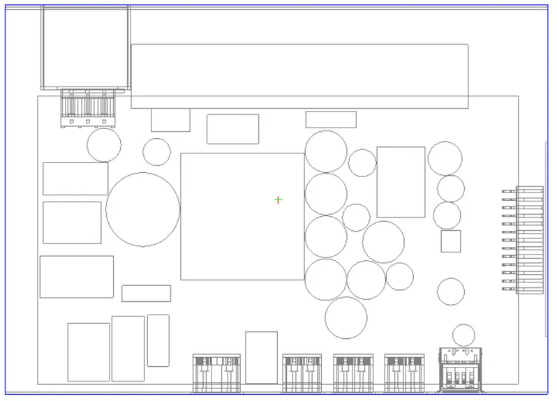
Week 3 - Geometry simplification of an Electronic enclosure assembly
Objective:-
The objective of the project is to convert CAD shapes into Icepak primitive shapes in Spaceclaim & modify the components in Icepak & define the correct physics.
Procedure:-
The given CAD model of an electronic enclosure assembly is imported into SpaceClaim where the following steps are carried out:
- The bodies which have no effect on the focus bodies are removed from the geometry.
- Using Icepak commands, the CAD shapes in the geometry are converted into Icepak primitive shapes.
Types of bodies:
The thermal analysis of the electronic component is a crucial part of the design. The CAD model does not describe the function of each component in the system. Thus the components in the system are assigned the function like heat generation for the processor in the PCB (Printed circuit board). The components in the CAD model of the electronic component are initially classified according to their thermal effect on the system. The components are classified as focus bodies, necessary bodies, peripheral bodies, and dispensable bodies. The components are converted by Icepack objects such that they are detected in the Icepack thermal management software. The objects that are not detected as the Icepack objects are simplified such that the software detects them as the electronics component.
- Focus bodies - The bodies which will emit some heat or obstruct the flow of the system.
- Necessary bodies - The bodies which will have some effects on the focus bodies.
- Peripheral bodies - These bodies may or may not affect the focus bodies.
- Dispensable bodies - The small bodies on the assembly which has no effect on the physics of the system, these bodies are completely neglected.
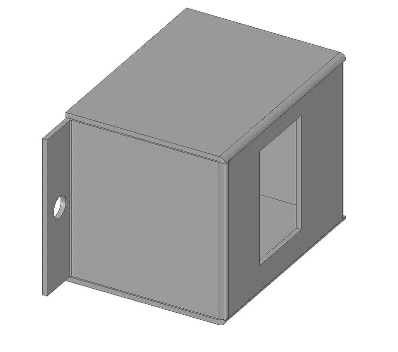
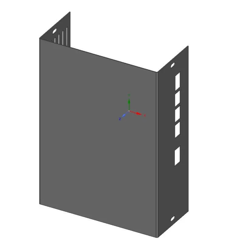
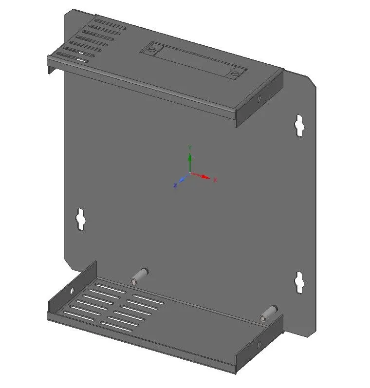
Classification of the electronics components:
1. Focus bodies: Are of greatest interest.
Processor, PCB, Fins
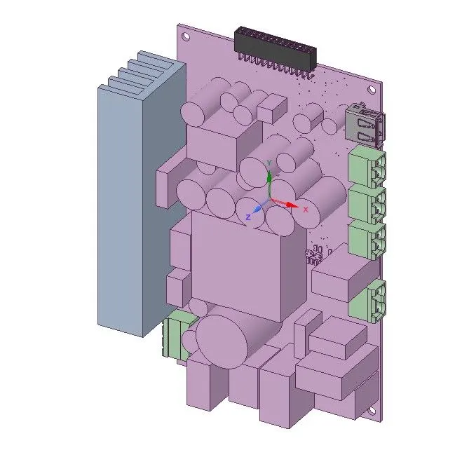
1. Necessary bodies: Affect focus bodies.
Resistor and capacitors
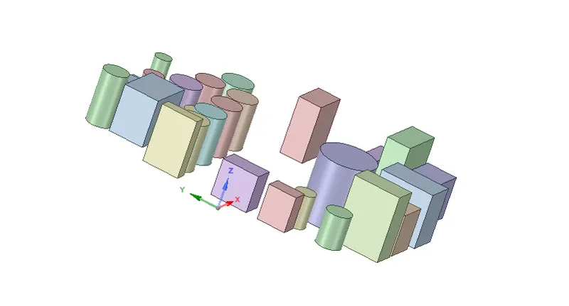
1. Peripheral bodies: Influence on focus bodies is uncertain.
Power ports
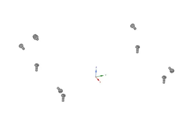
1. Dispensable bodies: No effect on focus bodies.
Bolts, nuts
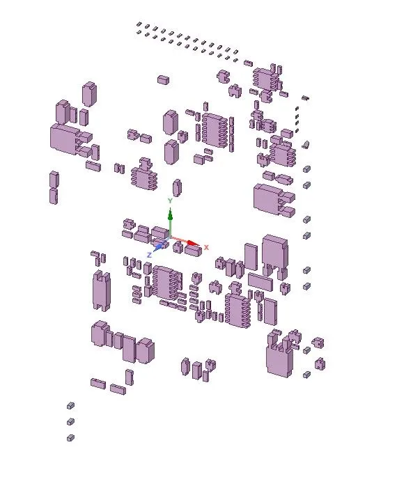
Delete Curvature - The curvature is used to increase the strength of the body which has no effect on flow or thermal analysis & these surfaces create complexity during the mesh which affects the final solution. Select the fillet & click on selection on the left column which finds all the similar fillet edges & these are deleted using the delete option.
To Delete the rounds/chamfers and Fills the Hole
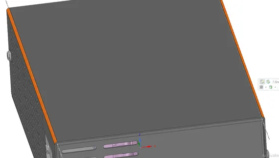
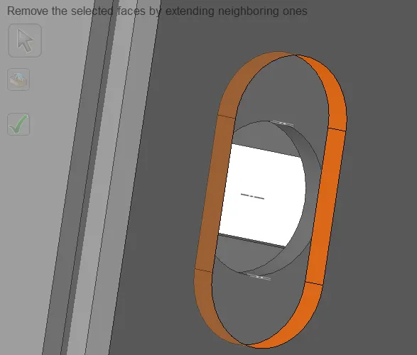
The geometry required for performing thermal analysis using Icepak can often be directly prepared in Icepak. However, in some cases, the designer may choose some other CAD software to prepare the geometry. In such cases, the CAD geometry must first be converted into primitive Icepak shapes using the commands available in SpaceClaim.
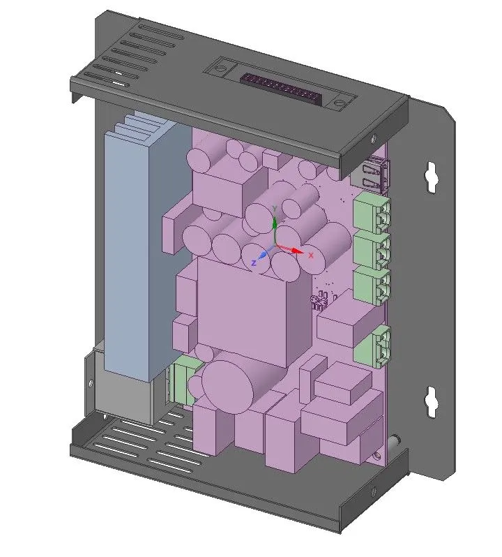
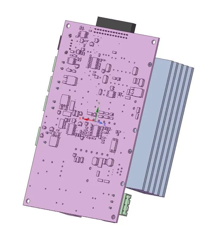
The following steps are used to simplify the CAD geometry (shown above) into Icepak Objects:
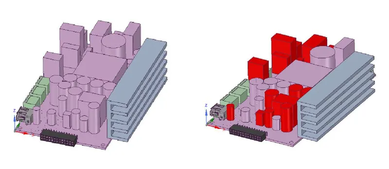
This part is divided into multiple parts by using the Split Body command with the top and bottom planes of the PCB. This separates most of the components from each other. Identify Objects command is used to identify and convert CAD geometries of the bodies into Icepak Objects. The image attached below shows the different parts identified for conversion to Icepak Objects. (The parts are highlighted in red)
1. Level 0 - Bounding box
In this type of simplification, the object is converted to a cuboidal block irrespective of its shape. In the present study, the Processor and PCB board are given the Level 0 simplification.
CAD Before and After Simplication
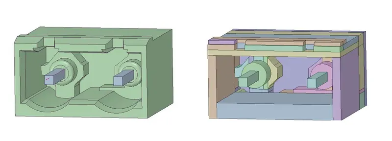
2. Level 1 - Non-polygon shapes
In this simplification, the component is converted into a collection of blocks. In this analysis Fin, all the ports are converted to level 1 simplification.
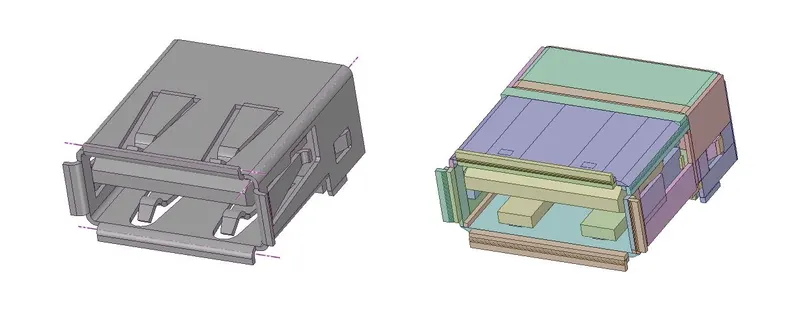
3. Level 2 - Polygonal
The geometry take the polygonal shape.
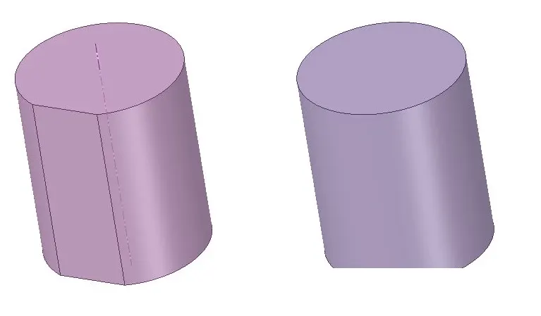
4. Level 3 - CAD block
The simplification takes place according to the shape of the component.
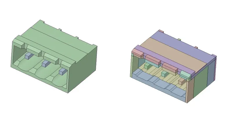
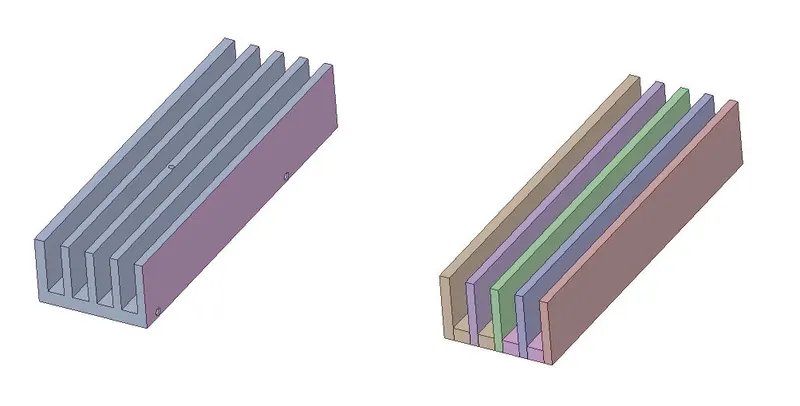
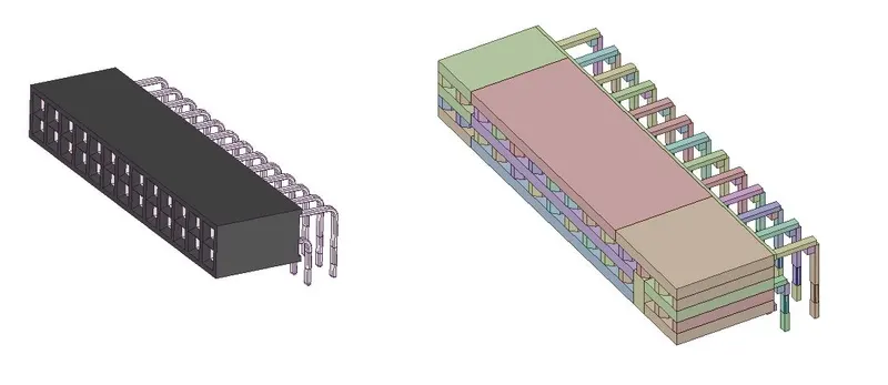
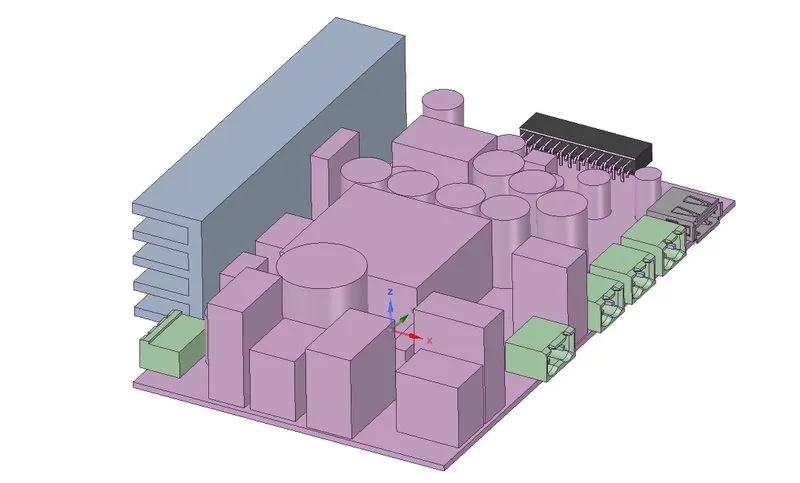
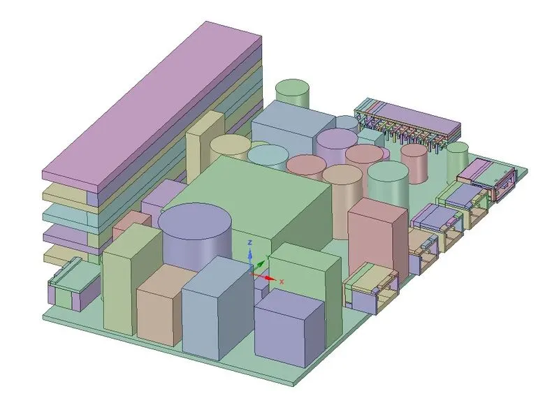
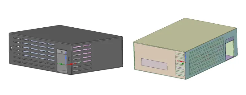
After simplification, the geometry is saved as an Icepak project. A workflow with the following two standalone systems is created in ANSYS Workbench:
A. Geometry
B. Icepak
The two standalone systems are linked such that the geometry imported/created/simplified in the Geometry tab of system A (Geometry) is transferred to the Setup tab of system B (Icepak). The image attached below shows the workflow created in ANSYS Workbench.
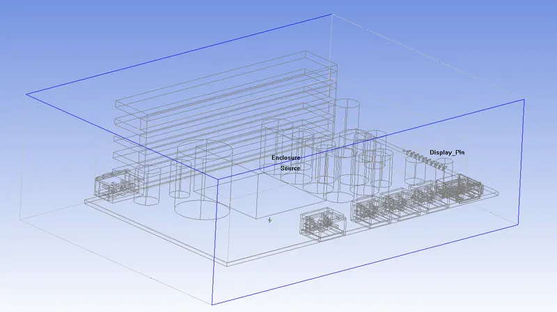
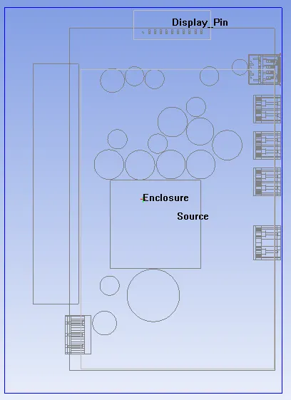
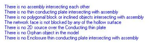
After the interfering geometries are moved apart from each other manually in Icepak, the Macros Automatic Case Check Tool is applied. The image attached below shows the output of the Macros.