Week 10 - MRF project
Objective:- The main objective of this project is to provide analysis and standards for modeling MRF fans using ICEPAK.
Theory:
The MRF model is, perhaps, the simplest of the two approaches for multiple zones. It is a steady-state approximation in which individual cell zones move at different rotational and/or translational speeds. The flow in each moving cell zone is solved using the moving reference frame equations.
CFD applications include fluid moving around or inside of stationary objects. Meshes are hence fixed. Incompressible Steady Navier-Stokes equations are solved if the flow is incompressible. Flow inside of pipes and flow around airfoils are two very typical uses. Since the airfoil and pipe are stationary in both situations, the incompressible steady Navier-Stokes equations are used to solve the meshes.
A steady-state approach used in industrial computational fluid dynamics to model challenges with rotating components is the Moving Reference Frame (MRF) approach. It is thought to need less computer power while efficient enough for most industrial situations.
This strategy’s underlying principles are straightforward but elegant. During the meshing phase, a small volumetric zone of mesh cells is produced around the spinning body, and the MRF zone encompasses this area.
The MRF zone is rotated around the body’s axis while the body remains still during the simulation phase. In a reference frame that rotates or moves at the same speed as the rotating or moving geometry, governing equations are solved. On a physical level, it means that we see the flow field around the moving body while seated on it. The flow field becomes stable concerning the geometry as a result.
- The Moving reference frame approach is a steady-state method employed in industrial Computational Fluid Dynamics (CFD) to model problems with rotating parts.
- It is considered to be less computationally expensive and yet accurate enough for most industrial problems.
- The underlying physics behind this approach is simple.
- A thin volumetric region of mesh cells is created around the rotating body during the meshing phase. This region is known as the MRF zone.
- During the simulation phase, the MRF zone is rotated about the axis of the body and the body is kept stationary.
- In order to preserve the direction of Coriolis Forces on the body, the rotational velocity of the ball is reversed in the MRF zone.
Geometry:
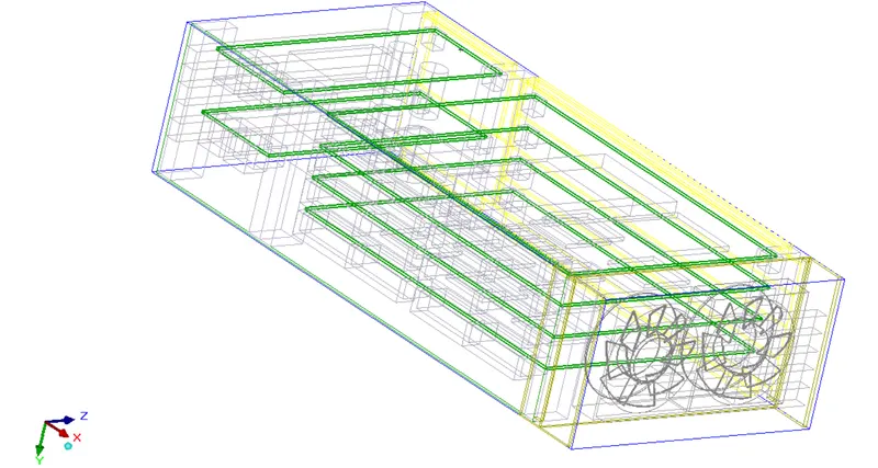
The geometry of the cad model is in the dimension of 730x12x180, with inlet and outlet vents.
fan properties:
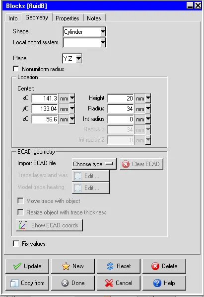
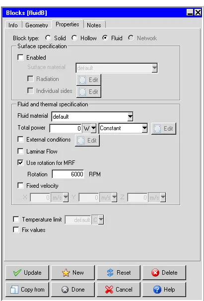
RPM of 6000 is set to fan model
Meshing:
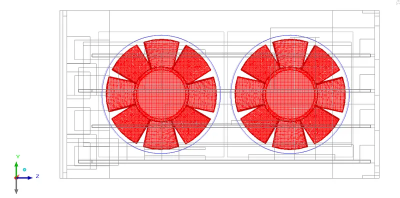
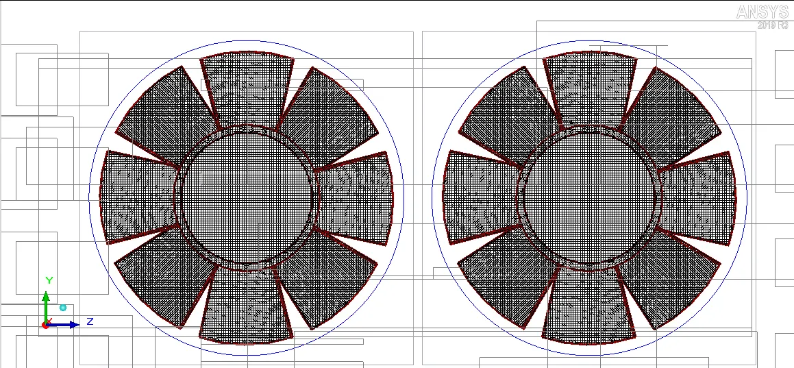
Meshing assemblies are separately done to obtain non-conformal meshing.
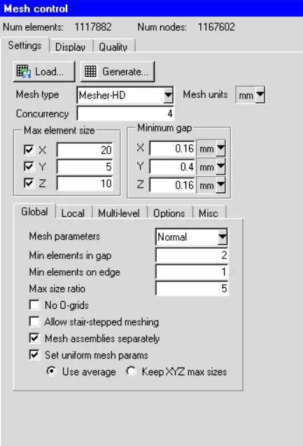
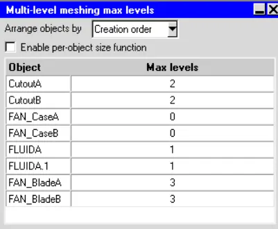
Multi-level meshing is done to reduce the mesh counts.
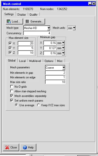
To check for validation of mesh
Macros>> productivity>> validation>> automatic case check tool
It checks the assembly interface between the various objects and the assembly.
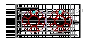
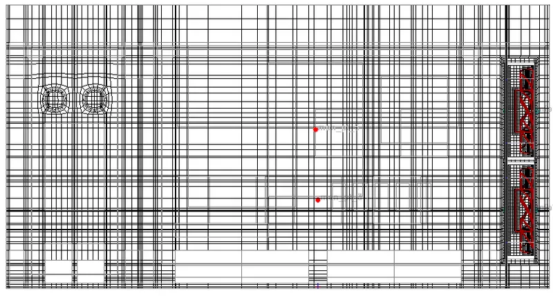
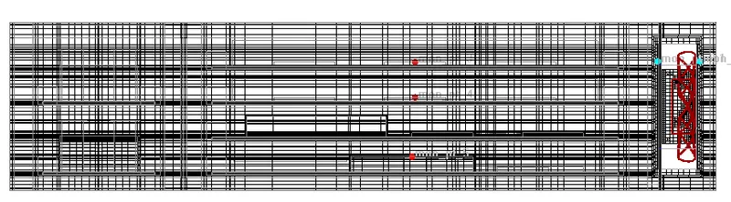
Mesh model for an fan object
General setup:
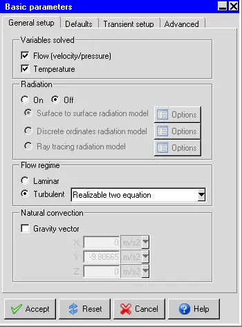
Boundary conditions
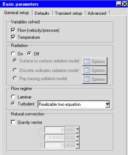
- Flow conditions
- Temp 20 degree
- Pressure 0Pa
- Radiation temp 20degree
- Default fluid air
- Default solid extruded Al
- Radiation: off
- Transient setup: steady
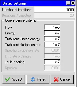
- No of iterations: 1000
- Flow convergence: 0.001
- Energy convergence: 1e-10
- Joule heating: 1e-7
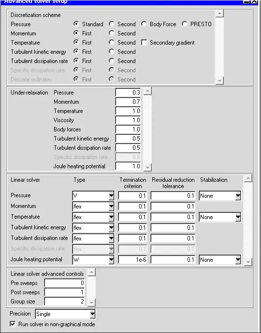
- Parallel setting:
- No of processors- 4
Post-processing plots
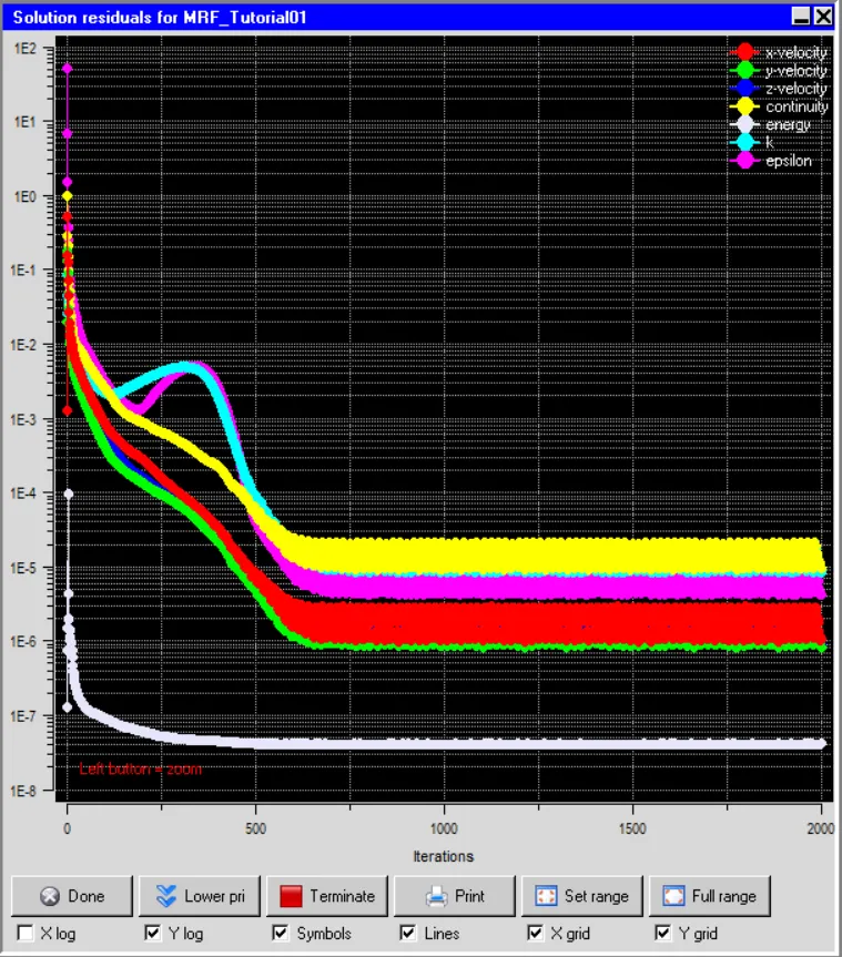
Residual Plot
The residuals for the following equations are plotted against the number of iterations:
- Continuity equation
- X-momentum equation
- Y-momentum equation
- Z-momentum equation
- Energy equation
Temperature object contour
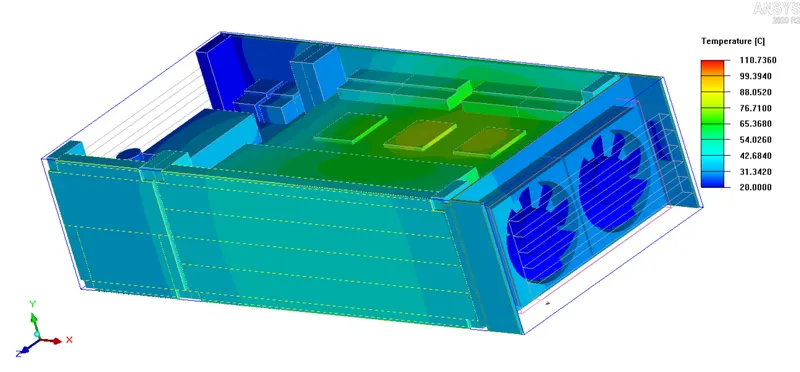
Plane Y-Z Plane Z-X Plane X-Y
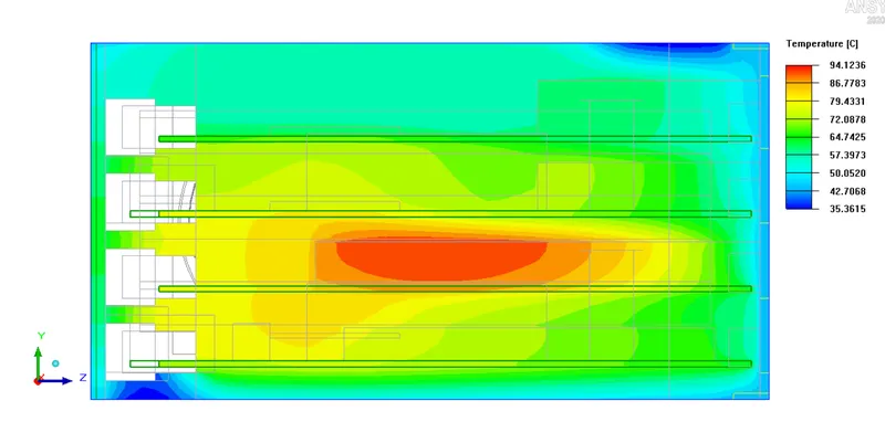
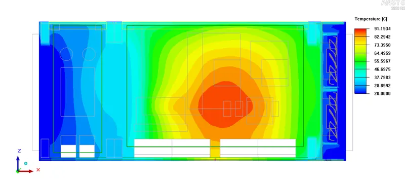
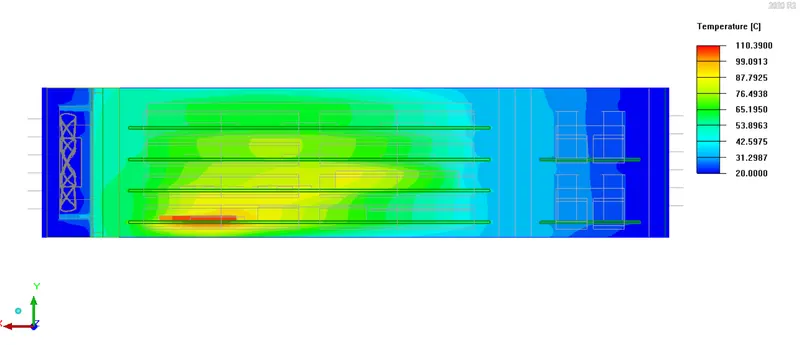
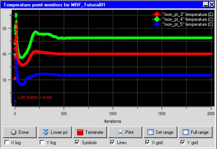
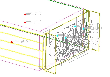
Temperature monitor points:
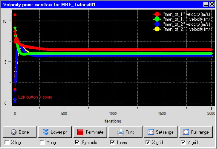
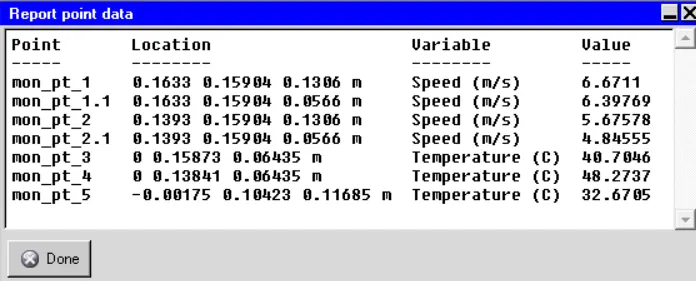
Velocity monitor points:
Plane Z-X Plane X-Y
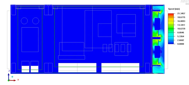
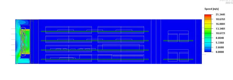
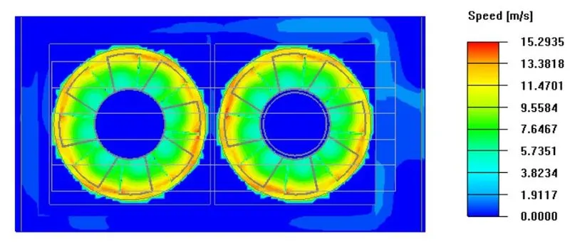
Velocity streamlines:
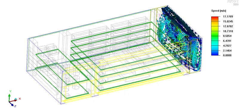
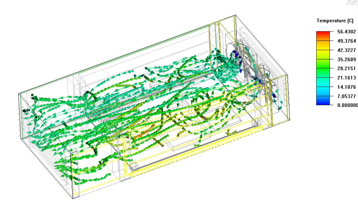
Conclusion:
- MRF reduces error in the prediction of the temperature of components because it throws the flow directly into components. MRF model is precise in predicting flow, turbulence, and noise level. This model gives an accurate prediction of flow, and temperature in high-density electronics.
- Moving Reference Frame (MRF) modeling enables more accurate predictions of the flow.
- MRF reduces errors in predicting component temperatures because it directly throws the flow onto the components. This phenomenon we can't get through the normal modeling of the fan.
- MRF modeling is very accurate in predicting flow, turbulence, and system noise levels.
- This model also gives accurate results of flow, temperature, and some other parameters even in high-density electronic models.