Week 5.2 - Multi Level Meshing
Objective:- The objective of the project is to create multi-level meshing to resolve CAD objects in the Icepak model and reduce the original mesh elements.
Assignment:-
- Create non-conformal mesh assembly and use mesh separately option with slack values.
- Use set uniform parameters and use average on 1 assembly, in the multi-level meshing tab allow multi-level meshing up to level 2for the objects.
- Generate mesh & observe mesh reduction.
- Do visual inspection & check for quality diagnostics.
Introduction:-
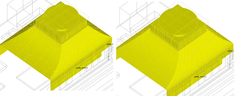
The Icepak model is given for this assignment. Open and unpack the given hanging_node.tzr model. Without any modifications, the model results in about 700,000 elements. Note that this mesh count results from using the non-conformal meshing technique, which reduces mesh bleeding and mesh count. You can reduce the mesh count and improve the mesh resolution on and around the CAD objects by using the multi-level meshing technique. This procedure starts with a coarse background mesh and resolves fine-level features through a series of successive mesh refinements. By using multi-level meshing and the uniform mesh parameters feature, you can reduce the mesh count to approximately 500,000 elements and improve mesh resolution
Geometry:-
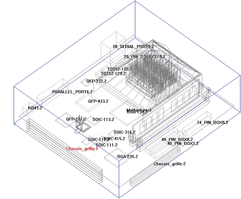
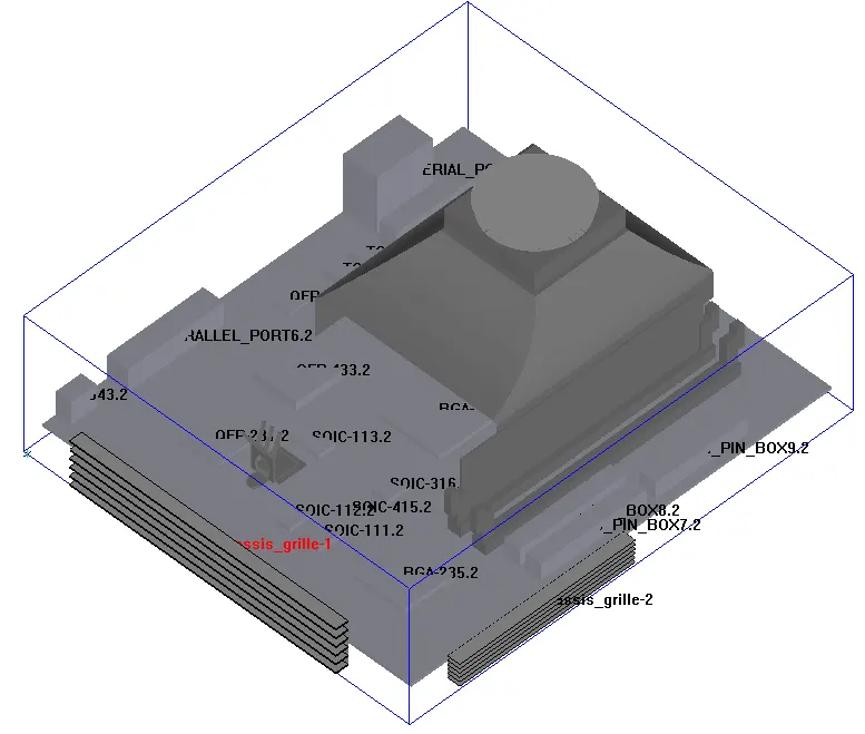
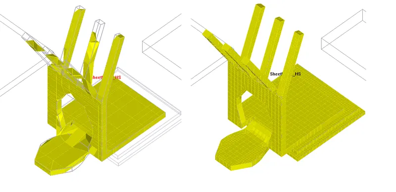
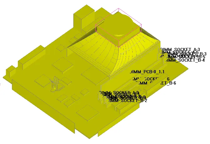
The below picture is the given CAD Model to generate the mesh using the multi-level parameters.
- Fan
- Capacitors
- Solid blocks
- Heat sink
- Printed circuit boards, etc.
Import Model:-
File --> unpack project --> hanging node.tzr - This opens the hanging node model and click on View --> default shading --> solid
Model Check
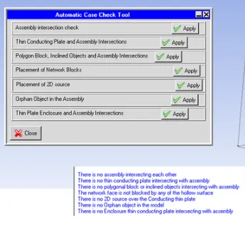
Macros --> Productivity --> Validation --> Automatic case check tool - It checks the assembly interface between the various objects and assembly.
Meshing:-
- For the first time, the mesh is generated for the Mesh assemblies separately. This means a non-conformal mesh is performed.
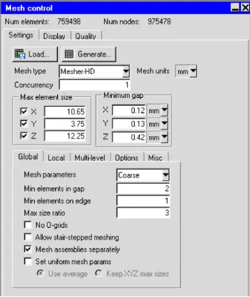
A non-conformal mesh is when there are partial or zero matchings of nodes at the interface. This means that one, few, or every node on one side of the interface doesn’t have a match on the other side of the interface. - For a general non-conformal mesh the number of elements produced is 759498 and the number of nodes is 975478 with coarse mesh is in use.
Multi-Level Meshing
- It enables local refinement from a starting Cartesian mesh generated using the max sizes you specified. Multi-level meshing is useful if you have a large variety of length scales in your model. The refinement can be controlled such that the initial mesh is refined in an area where the mesh needs to be finer in order to resolve some geometrical features or gaps. This will significantly reduce the overall mesh count while providing adequate mesh resolution where it is needed. Multilevel meshing applies to 2D and 3D cut cells as well as stair-stepped meshing.
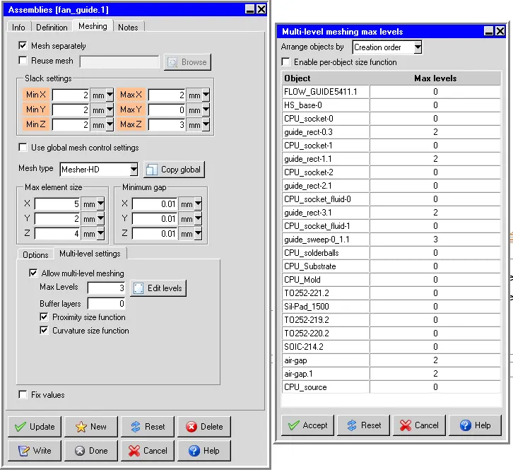
- Max levels are the maximum number of levels that may be required to achieve the desired mesh refinement based upon curvature/proximity. For a given coarse mesh the desired proximity/curvature-based refinement may be achieved even before reaching the max levels.
- Edit levels enable you to specify refinement levels for selected objects. Per-object meshing levels can be used in conjunction with the max level and size functions. When Enable per-object size function is enabled, the site functions (proximity and/or curvature) are used to subdivide the mesh around the object up to the max level specified for the object. When Enable per-object size function is disabled, the mesh is subdivided to the max-level everywhere on the object.
- The objects around the Fan guide are grouped into an individual assembly for the further reduction in the mesh elements.
Mesh Control
ii) Mesh type - Mesher -HD
- Max element size X - 10.65mm
- Max element size Y - 3.75mm
- Max element size Z - 12.25mm
- Min Gap X - 0.12 mm
- Min Gap Y - 0.05 mm
- Min Gap Z - 0.042 mm
Mesh assemblies separately
It indicates whether or not ANSYS Icepak should generate a non-conformal mesh for the assemblies that have the Mesh separately option turned on. This option enables you to turn off (or on) all defined non-conformal meshing for the entire model. The separate assembly for the objects around the Fan guide is created.
Mesh on X Plane
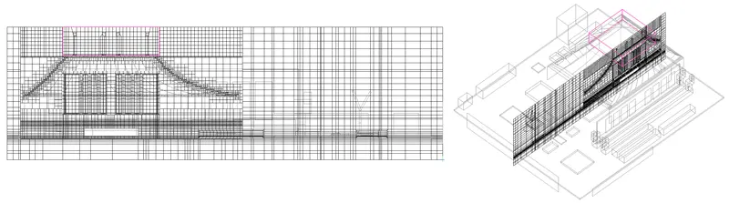
Mesh on Y Plane
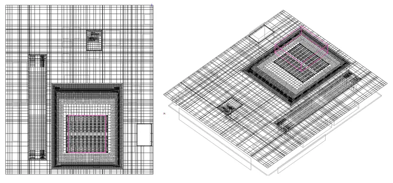
Mesh on Z Plane
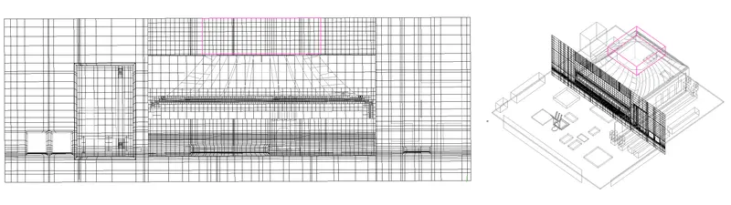
Surface Mesh
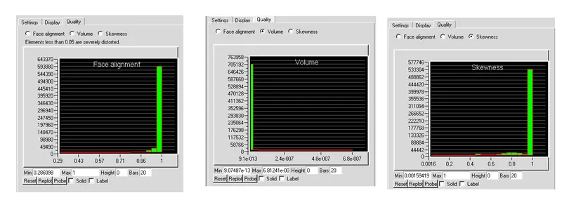
Mesh Quality
Face alignment
The face alignment is a measure of mesh quality defined by the face-alignment index bar (C0.C1).bar(f)
- Where C0 and C1 are the centroids of the two adjacent elements and are the normal vector to the face between the two elements.
- Range from 0 (bad) to 1 (good).
- Face alignment >0.1 (preferred), >0.5 (must), 0.15> (best).
Volume:
- Volume is, the preferable volume of mesh to be greater than 1e-13 for a single-precision solver.
- Volume >1e-15 for double precision solver as long as the total magnitude of the model is <12(i.e. 1e-15 - 1e-13).
- Max/min cell volume should be <10^7 for a single-precision solver.
Skewness
- It is one of the primary quality measures for a mesh. According to the definition of skewness, a value of 0 indicates an equilateral cell (best) and a value of 1 indicates a completely degenerate cell (worst).
- Skewness is defined as the difference between the shape of the cell and the shape of an equilateral cell of equivalent volume.
- A general rule is that the maximum skewness for a triangular/tetrahedral mesh in most flows should be kept below 0.95, with an average value that is less than 0.33.
Conclusion
The multi-level meshing technique is used in the model to capture the CAD model and also a reduction in 2 lakhs mesh elements the generated mesh is visually inspected and also the mesh quality is checked using three criteria - face alignment, skewness, and volume. From these data, it is concluded that better resolution of CAD objects and reduction in mesh count is achieved using the multi-level meshing technique.