Week 3 Sheet metal Bending challenge
Objective: To perform sheet bending analysis by varying materials, coefficient of friction and mesh size.
Software Used: Ansys Workbench 2021 R2.
Introduction:
In applied mechanics, bending (also known as flexure) characterizes the behaviour of a slender structural element subjected to an external load applied perpendicularly to a longitudinal axis of the element.
Bending test is used to determine the tensile strength of brittle materials that are generally difficult to test in uniaxial tension due to cracking in the grips. The most common bending tests include cantilever, 3- and 4-point bending, and G-torsion.
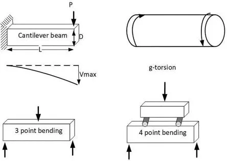
1) 3-Point and 4-point bending
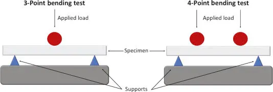
Bending tests are conducted by placing a length of material across a span and pushing down along the span to bend the material until failure. Bending tests reveal the elastic modulus of bending, flexural stress, and flexural strain of a material. 3-Point bending involves placing the material across a span supported on either ends of the material and bringing down a point source to the centre of the span and bending the material until failure while recording applied force and crosshead displacement. The 3-point description comes from the two points of support at the ends of the material and the one point of deflection brought down to the middle of the material. 4-point bending tests are conducted similarly to 3-point bending tests except that rather than one point source being brought down to the centre of the span of material two points slightly separated from the centre of the material are brought down in contact with the material. This separation of the two-point sources spreads the region of bending out from the centre such that a larger portion of the material is tested than with only one point of deflection. Hard materials like bone and implants can be tested using bending tests as a measure of the tissue or material in both tension (the bottom of the sample as it is tested) and compression (the top of the material as it is tested).
Materials Used:
Aluminium NL 1199, Copper Alloy NL, Magnesium Alloy NL &
Case setup & Execution:
Pre-processing:
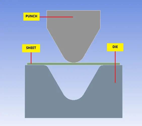
Geometry:
Meshing:
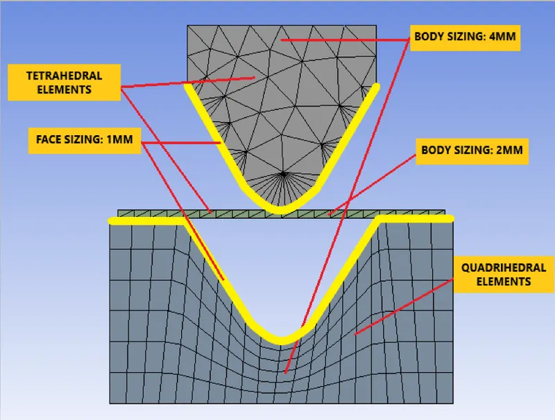
The present geometry has mesh of different sizes, the sizes are redefined considering ease of convergence of solver and to not exceed the limit of Academic Version.
Following are the mesh sizes, used in present simulation.
Boundary Conditions
Displacement of Die:
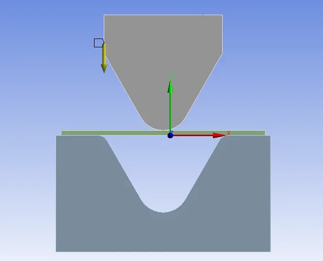

Displacement of Punch:
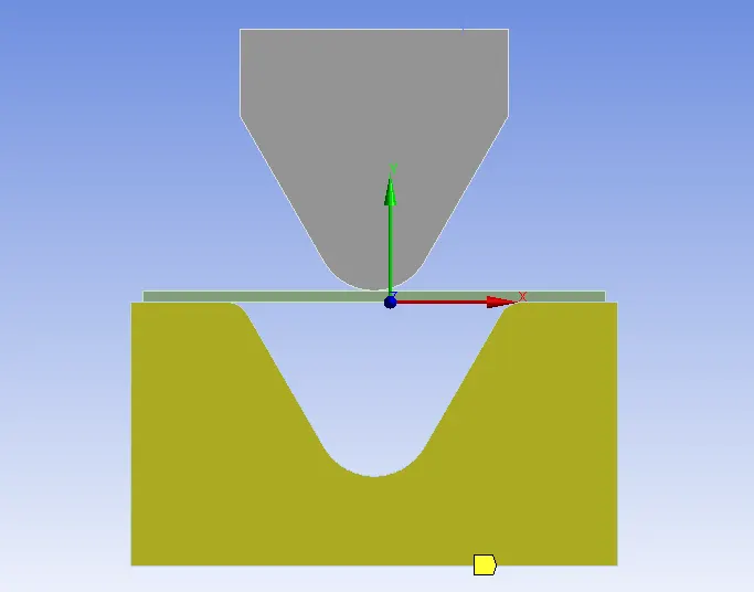

Displacement of Sheet:
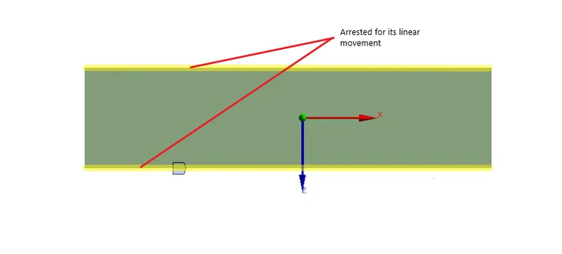
Sheet is arrested at the two faces and the type of contact in between sheet and die faces are frictional.
Overall Graph:

Analysis settings:
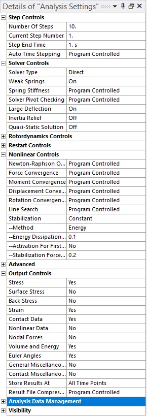
Case-1: Sheet bending Simulation with different materials:
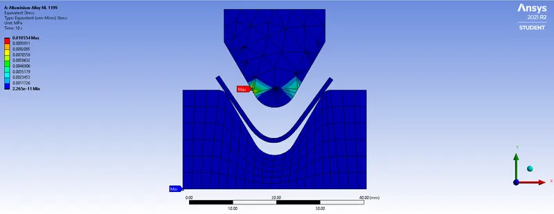
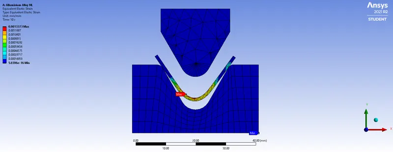
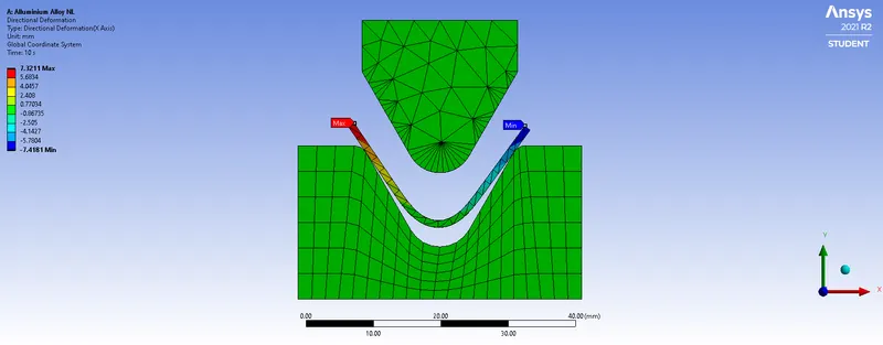
Aluminium Alloy NL 1199:
Equivalent stress
Equivalent strain
Directional Deformation
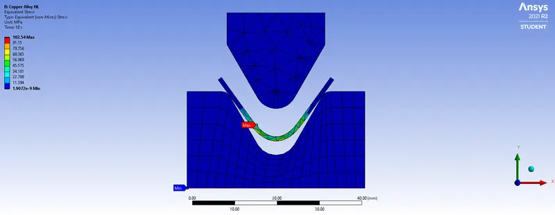
Copper Alloy NL:
Equivalent stress
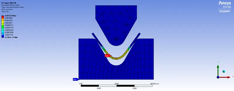
Equivalent strain
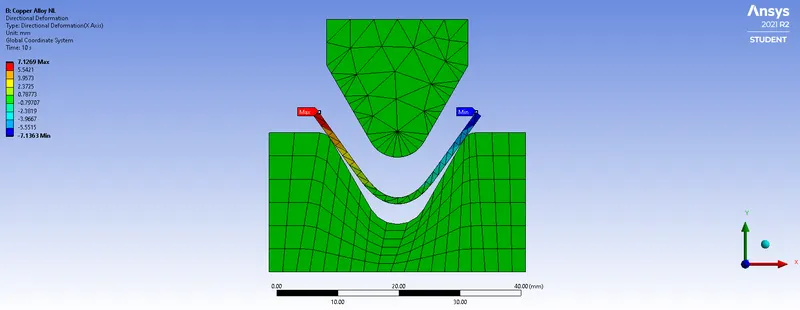
Directional Deformation
Magnesium Alloy NL:
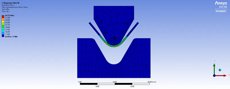
Equivalent stress
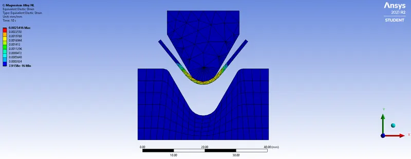
Equivalent strain
Directional deformation
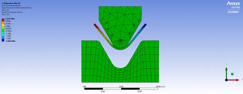
Results Comparison:
|
S. No |
Result / Material |
Al Alloy NL 1199 |
Cu Alloy NL |
Mg Alloy NL |
|
1 |
Directional Deformation |
7.3211 mm |
7.1269 mm |
6.3547 mm |
|
2 |
Equivalent stress |
1.0554e-002 MPa |
102.54 MPa |
64.355 MPa |
|
3 |
Equivalent strain |
1.3373e-003 mm/mm |
1.579e-003 mm/mm |
2.5416e-003 mm/mm |
From the above results, it is clearly shown that, Magnesium ally material does possess less deformation and equivalent stress
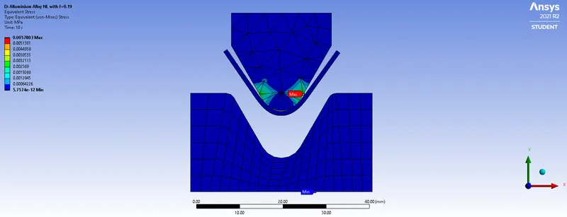
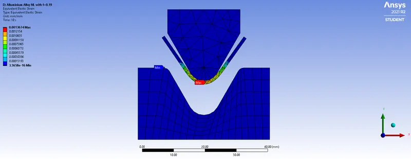
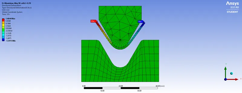
Case-2: Comparing the results with frictional coefficient=0.19 with that Aluminium Alloy NL 1199
Aluminium Alloy NL 1199 with frictional coefficient = 0.19
Equivalent stress
Equivalent strain:
Directional deformation:
Results comparison with Case-1:
|
S. No |
Results/ Frictional coefficient |
0.1 |
0.19 |
|
1 |
Directional deformation |
7.3211 mm |
7.4644 mm |
|
2 |
Equivalent stress |
1.0554e-002 MPa |
5.7803e-003 MPa |
|
3 |
Equivalent strain |
1.3373e-003 mm/mm |
1.3674e-003 mm/mm |
It is clearly shown that, with the increase of frictional coefficient, there is an increased stress and little increase in deformation and strain.
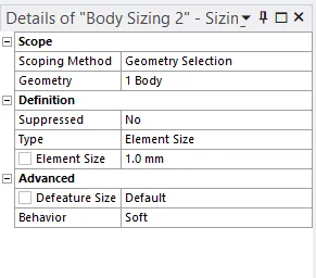
Case-3: To refine mesh size of sheet as much as possible and compare results with that of Case-1 results.
Maximum Nodes:
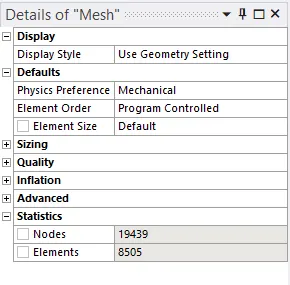
Refined mesh sheet details:
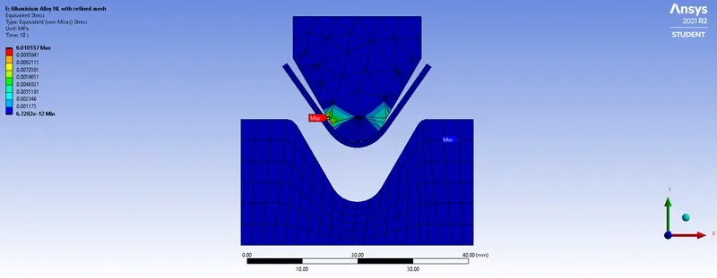
Equivalent stress:
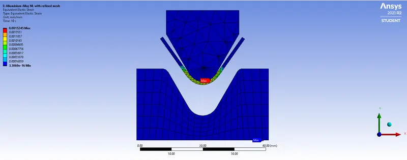
Equivalent strain:
Directional deformation:
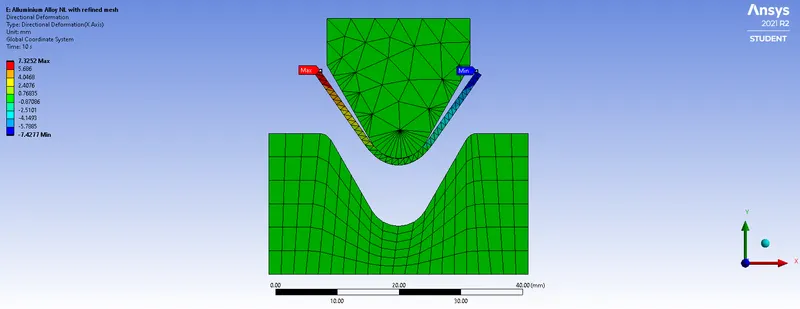
Results comparison:
|
S. No |
Results /Mesh size |
2mm |
1mm |
|
1 |
Directional deformation |
7.3211 mm |
7.3252 mm |
|
2 |
Equivalent stress |
1.0554e-002 MPa |
1.0557e-002 MPa |
|
3 |
Equivalent strain |
1.3373e-003 mm/mm |
1.5245e-003 mm/mm |
It is clearly shown that, with the refinement of mesh size, results are more accurate.
Conclusion:
The experiment on sheet bending subject to change in materials results that the die possesses more stress than on sheet with Aluminium as material. Whereas, in copper alloy and Magnesium alloy, maximum stress is on sheet bending area. Moreover, equivalent strain also more at the bending region. Directional deformation is more at the left end of the sheet in all three cases.
The experiment of sheet bending subject increase in frictional coefficient led to increase in stress and substantial increase of directional deformation and equivalent strain.
The experiment of sheet bending subject to decrease in mesh size gave more accurate results.
References:
-
Hiyam Farhat, Materials and coating technologies, in Operation, Maintenance, and Repair of Land-Based Gas Turbines, 2021
-
Yusuf Khan, in Encyclopedia of Biomedical Engineering, 2019