Week 2 Bevel Gear Challenge
OBJECTIVE:
To perform bevel gear simulation using ANSYS Workbench. The grid dependency test has to be carried out for the mesh sizes of 6,5 and 4 mm.
GRID DEPENDENCY TEST:
Mesh size is one of the governing factors in determining the accuracy of the solution. The grid dependency test is essentially used to investigate how the solution depends upon the mesh size. It is a known fact that reducing the mesh size or in simple terms refining the mesh to a smaller element size increases the computational cost. This is because solutions are interpolated at the nodes to get an approximate result. Hence, the higher the number of nodes higher would be computational time. On the other hand, a larger size of mesh leads to inaccurate solutions.
Therefore, a trade-off must be done to arrive at a result. The grid dependency test establishes the basic size of mesh which needs to be kept to get a consistent solution. It helps in determining the optimal mesh size where accurate results can be obtained. Refining the mesh further beyond this would result in a negligible change in the output results and also it increases the computational cost.
PROCEDURE FOR CASE SETUP:
1. Open ANSYS >> Drag and drop static structural in the project schematic window.
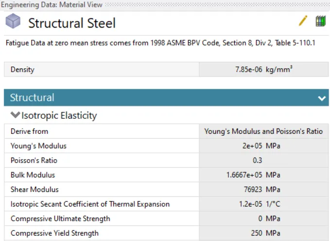
2. Go to engineering data for defining the materials given in the problem. The structural steel material is used for this simulation.
3. Select the model tab to establish the meshing, contact definitions, and analysis settings definition. Rename the parts according to convenience.
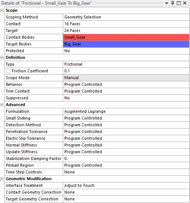
4. Go to contact and delete the default contacts. Now, create a frictional contact between the teeth of the bevel gears with a frictional coefficient of 0.1.
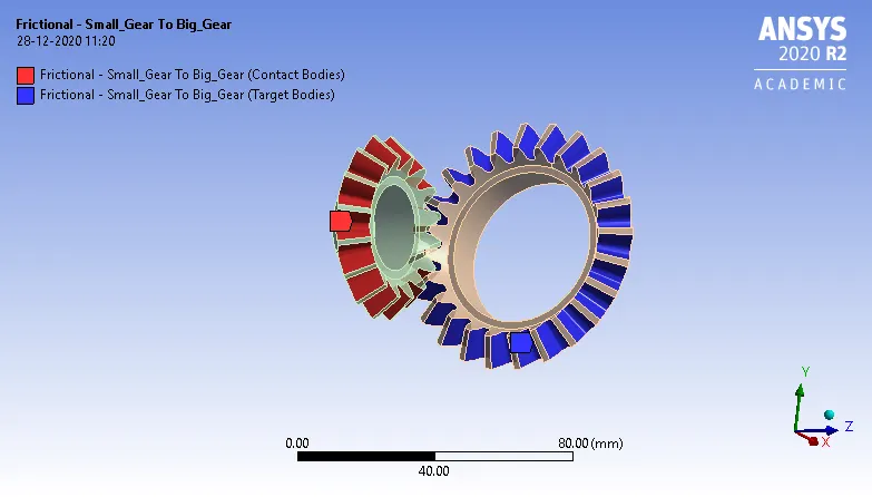
The contact definition is shown in the figure below.
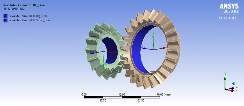
5. A body-ground revolute joint is defined for the two gears. This is shown in the figure below.
6. For meshing, an element size of 1.75mm is taken for the faces of the teeth. A mesh size of 4 mm is taken for the entire model. The mesh size below this provides a limitation to the academic limits available in the ANSYS.
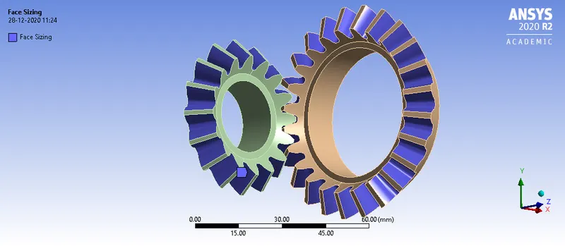
The final meshed model is shown in the figure below.
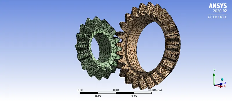
For further simulations, the mesh size is varied as given in the problem statement.
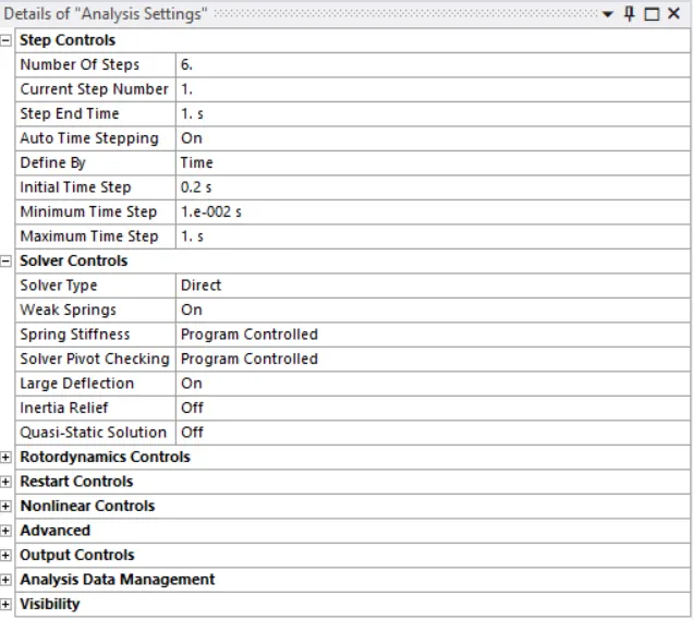
7. Go to analysis settings. The number of steps defined for this analysis is 6. For the first time step, the definition is shown in the figure below.
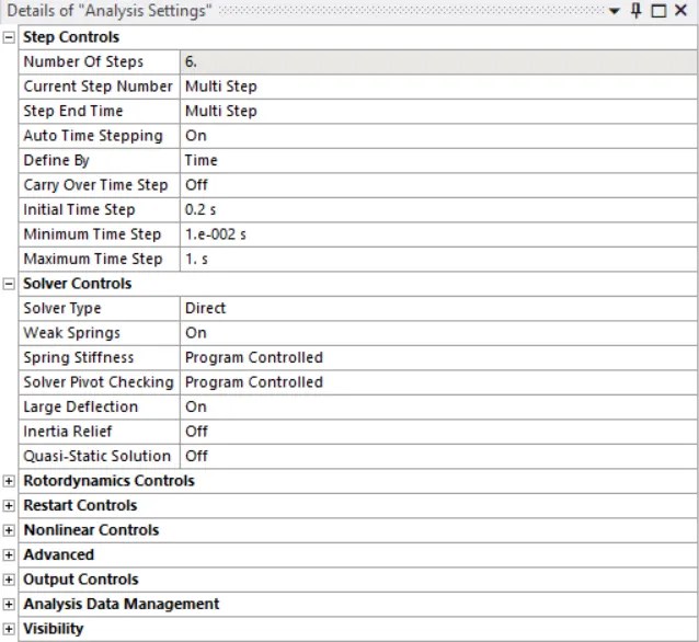
For the rest of the time steps, the definition is shown below.
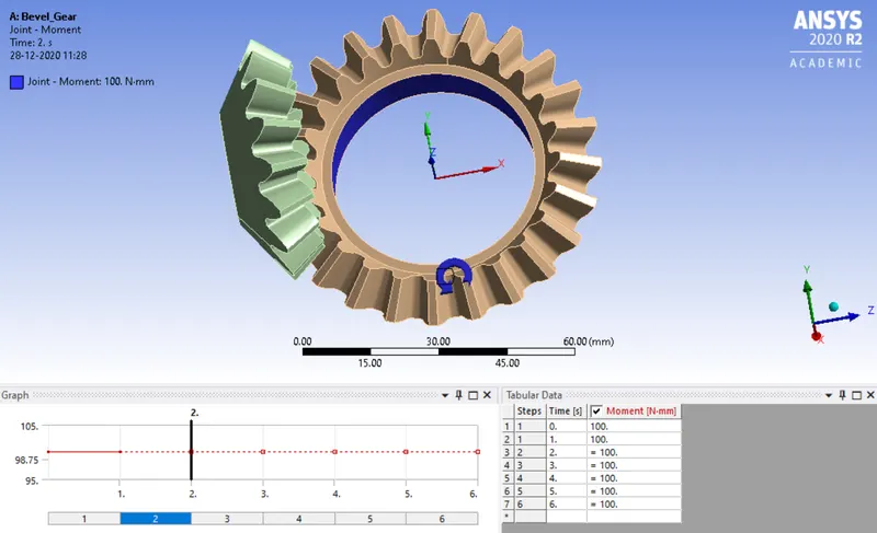
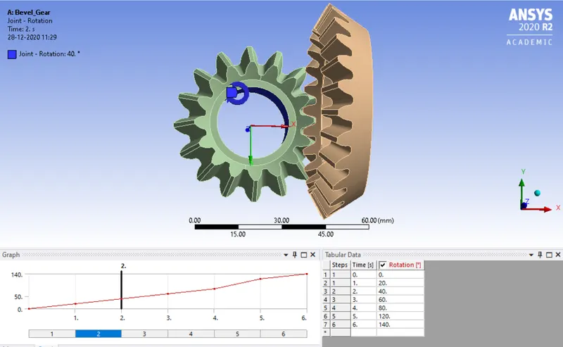
8. The boundary conditions are shown below.
9. The output requests for equivalent stress, equivalent elastic strain, and total deformation are placed.
10. From the analysis settings, hit on solve to start the simulation.
RESULTS AND DISCUSSION:
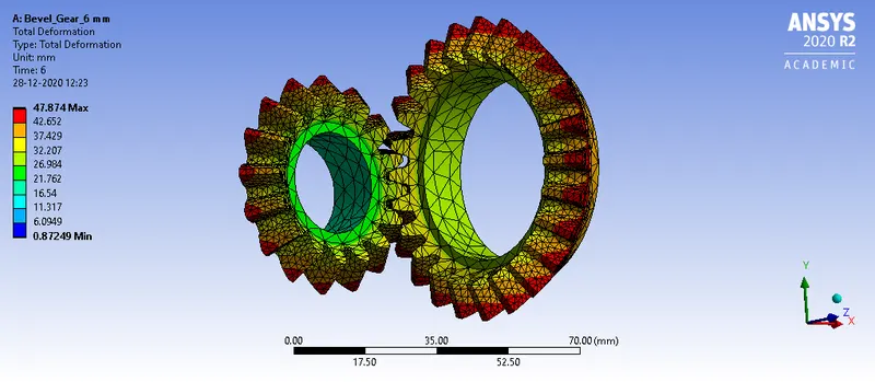
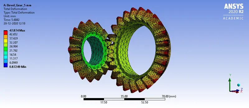
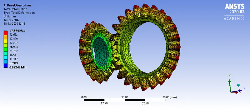
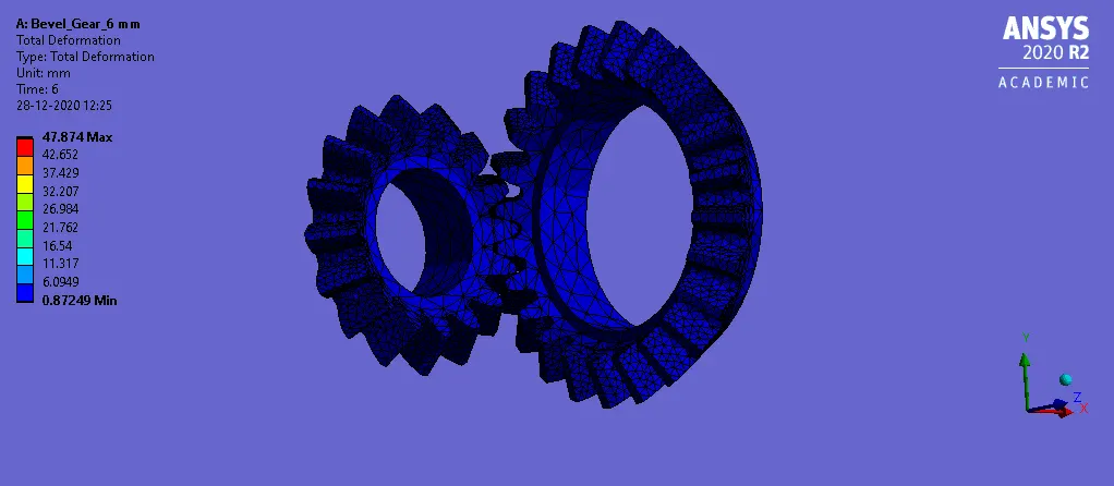
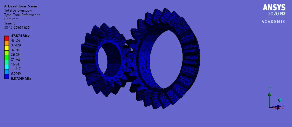
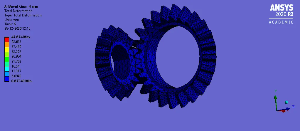
1. The total deformation obtained is shown in the figures below.
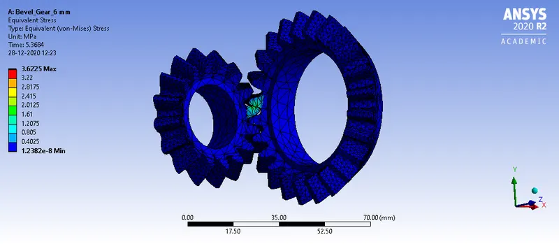
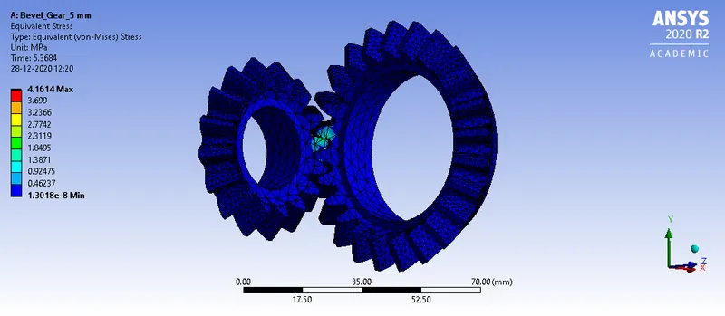
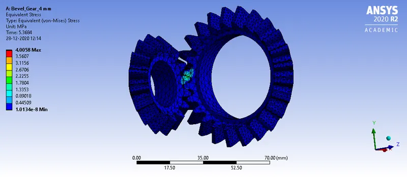
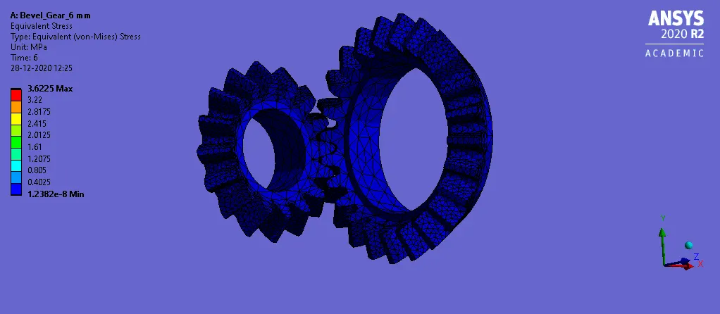
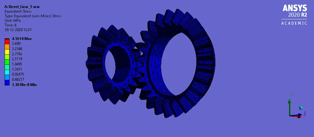
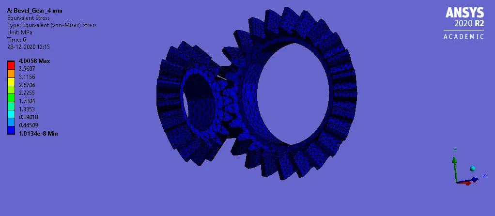
2. The equivalent stress obtained is shown in the figure below.
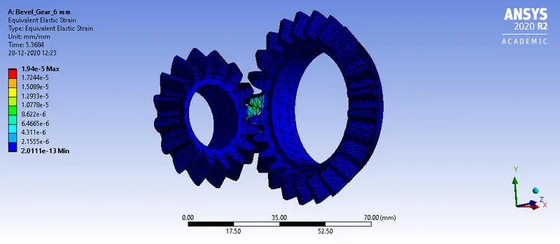
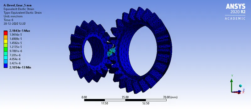
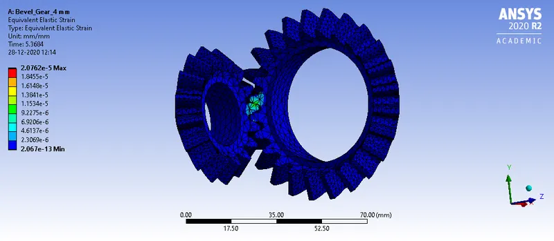
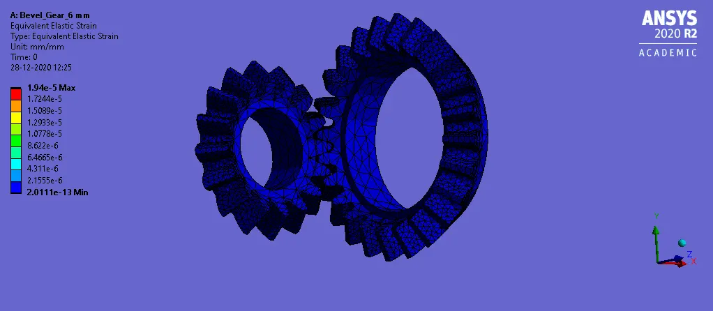
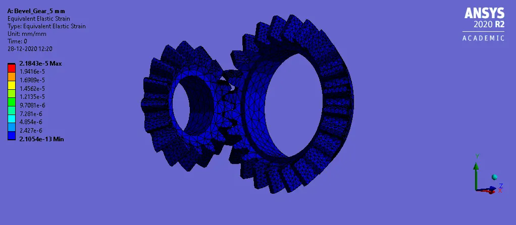
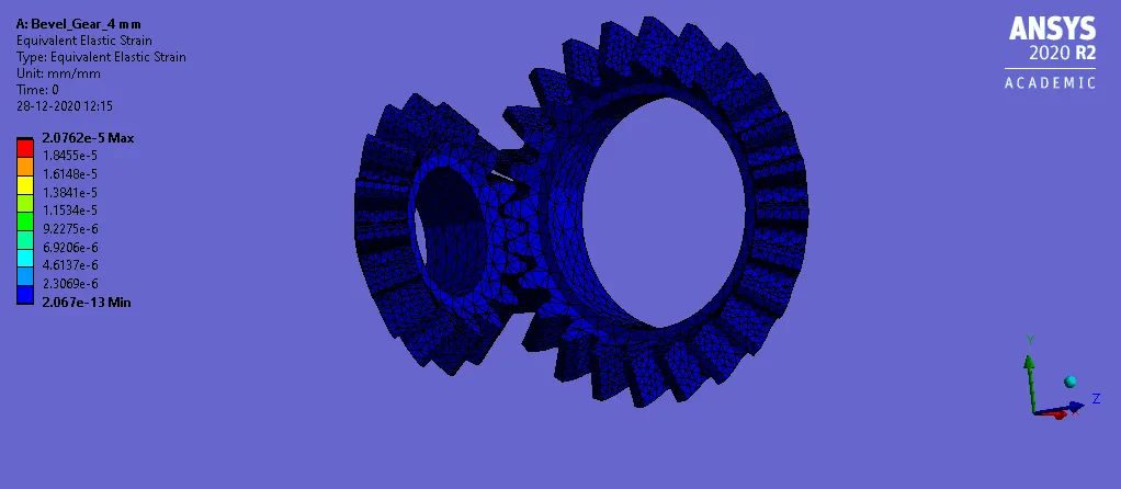
3. The equivalent elastic strain obtained is shown in the figure below.
ANIMATION FILES:
1. The total deformation obtained is shown in the figures below.
2. The equivalent stress obtained are shown below.
3. The results obtained for the equivalent elastic strain are shown below.
CONCLUSION:
From the simulation, it can be seen that for all the cases the solution converged without any errors.
The output parameters are tabulated below.
| Mesh Size | Total Deformation (in mm) | Equivalent Stress (in MPa) | Equivalent Elastic Strain |
| 6 mm | 47.874 | 3.6225 | 1.94e-5 |
| 5 mm | 47.874 | 4.1614 | 2.1843e-5 |
| 4 mm | 47.874 | 4.0058 | 2.0762e-5 |
The output from the ANSYS Parameter window is shown below.

From the above table, it can be seen that total deformation remains the same for all the mesh sizes with a value of 47.874 mm.
The equivalent stress varies considerably when the mesh is refined. The value obtained for a mesh size of 6 mm is 3.6625 MPa whereas for a mesh size of 5 mm the value obtained is 4.1614 MPa. For a mesh size of 4 mm, the value obtained is 4.0058 MPa.
The equivalent elastic strain varies considerably with the mesh size. For a mesh size of 6 mm, the value obtained is 1.94e-5. For the mesh sizes of 5 mm and 4 mm the value obtained is 2.1843e-5 and 2.0762e-5 respectively.
Hence, from the results, it can be seen that the accuracy of the solution increases as the mesh size is refined. The value of total deformation remains the same irrespective of the mesh size. The values of Von-Mises and equivalent elastic strain varies considerably with the mesh size. There is not much difference between the values obtained for a mesh size of 5 mm and 4 mm. Hence, the grid dependency test is carried out in the given model and all the objectives are satisfied.