Week - 5 - Modelling Spotwelds
OBJECTIVE:
To create and compare the simulation results of spotwelds using beams and solids elements. The following objectives are to be satisfied in the model.
1. To create 3-7 spotwelds in a symmetric manner.
2. To compare the axial and shear force for both the cases.
3. To describe the failure of spotweld at half of the termination time.
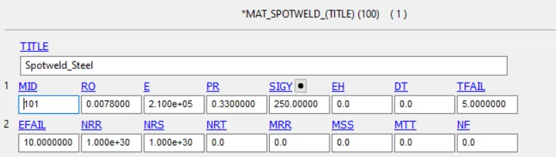
4. To use *MAT_SPOTWELD to define the material properties for spotweld.
PROCEDURE:
1. Open LS-Dyna Project Manager>>Start LS Prepost>>Import the given model.
2. Open Keyword Manager>>Part>>Define the parts with proper name. This is shown in the figure below.
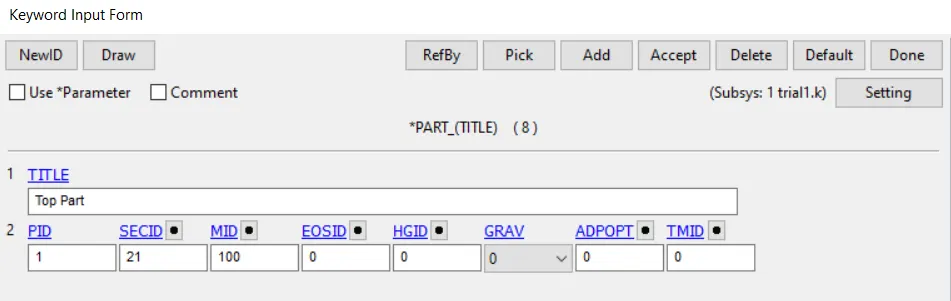
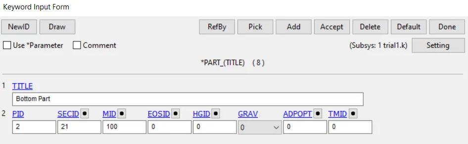
3. Define the material as steel for the top and bottom parts and create a shell section as shown in the figure below. Assign the corresponding properties to the part card.
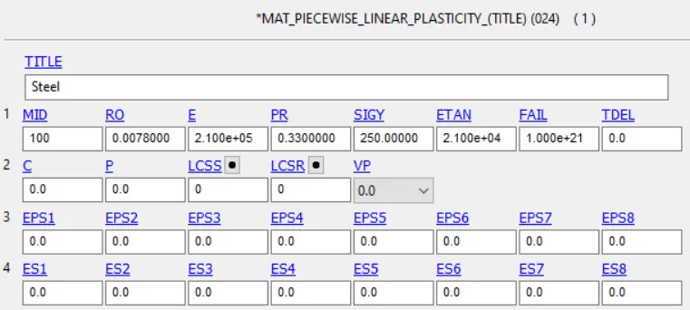
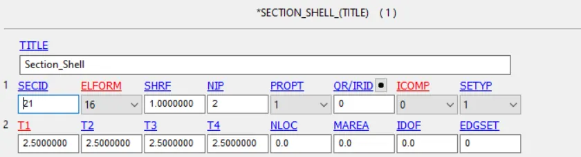
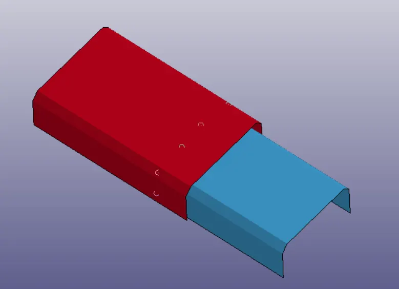
4. Go to Element and Mesh>>Element Creation>>Select Beam type>>Pick the nodes between two parts and create the spotwelds with new part ID for all the welds. This is shown in the figure below.
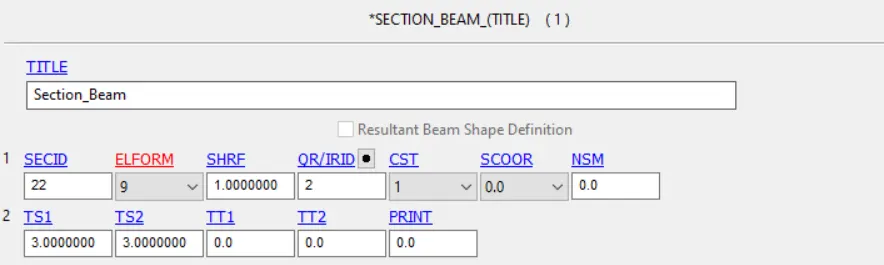
5. Now create the material as steel and section as beam for the welds. Assign the property to all the spotwelds.
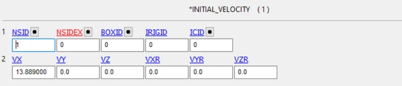
6. Now create a nodeset which contains all the nodes in the top and bottom part. This is for defining the velocity card for the parts.
7. Go to keyword Manager>>Create a velocity card and give a velocity of 13.889 mm/ms which is 50 km/hr.
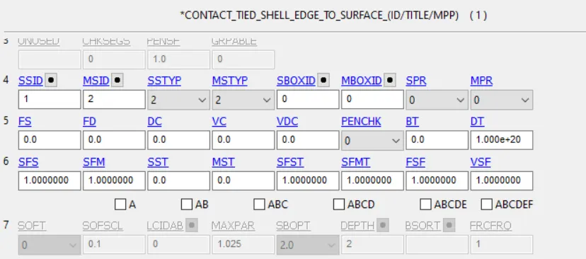
8. Go to Keyword Manager>>Contact>>Create a tied contact interface for the spotwelds and automatic surface contact for the bracket parts. For spotwelds the master surface is bracket parts and slave is spotweld. This is shown in the figure below.
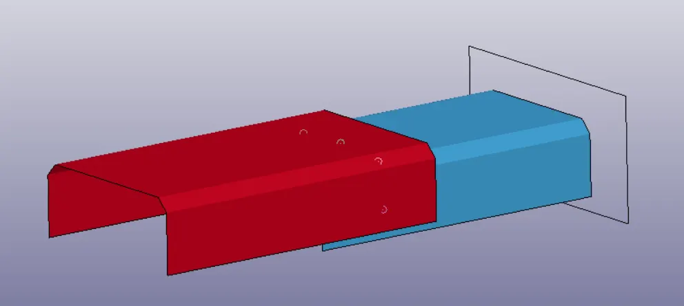
9. Now create a rigid wall to create an impact of the bracket against the wall. The wall position is shown in the figure below.
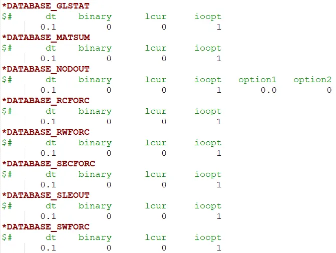
10. Go to Keyword Manager>>DATABASE>>ASCII_OPTION>>Define the necessary output files with a proper timestep values. This is shown in the figure below.
11. Now create a control termination card for a total runtime of 10 ms. The spotwelds would fail at 5 ms as defined the above card.
12. Assign the material card and section card for the corresponding parts and save the file using a proper name with .k extension.
13. Go to LS Dyna Manager, run the simulation.
RESULTS AND DISCUSSION:
1. The simulation results are shown in the figures below.
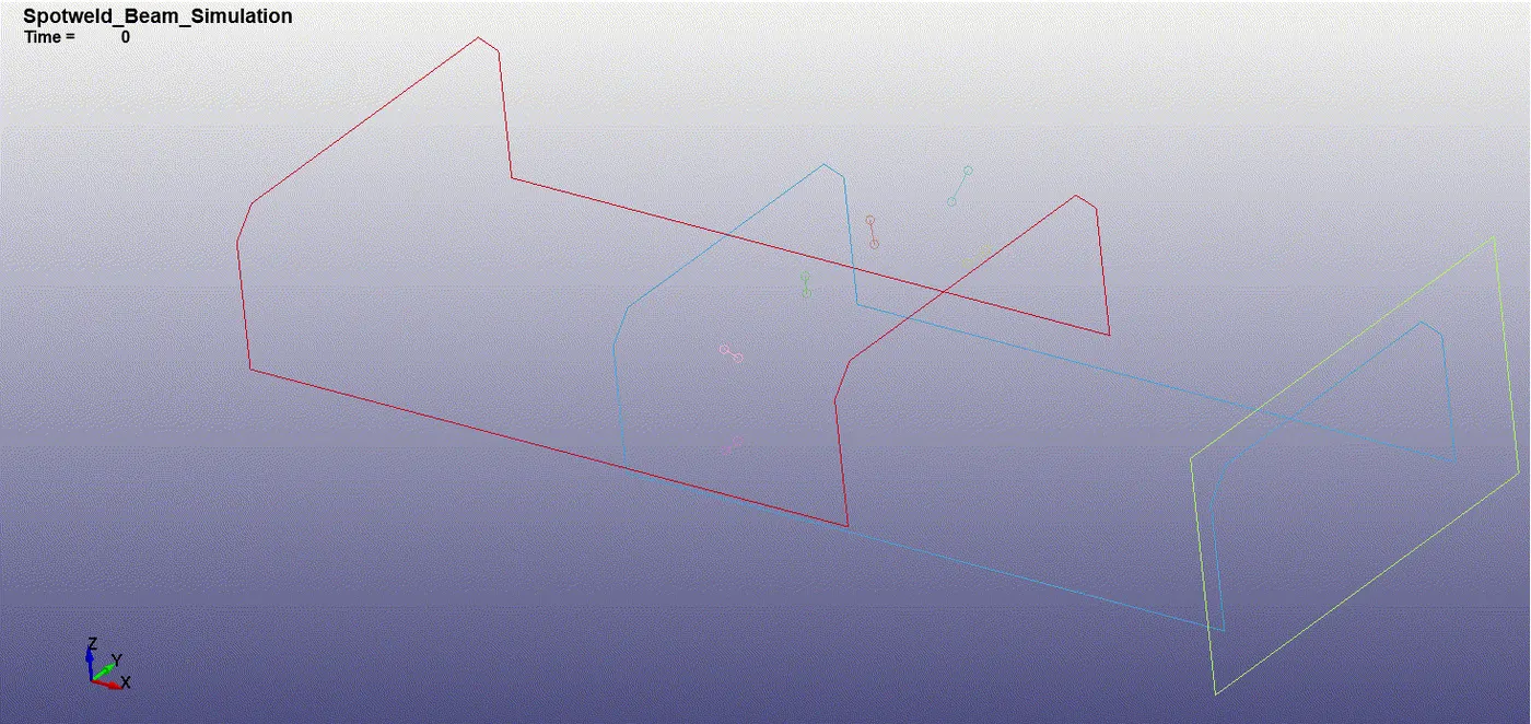
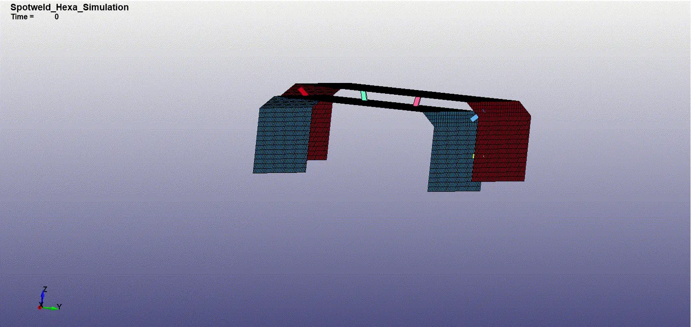
From the animation it can be inferred that the welds fail at exactly 5 ms int a total run time of 10 ms. The rebound is slower in the case of hexa spotweld. This is because the inertia offered by the hexa welds is higher when compared to beam elements. At 5 ms after the weld failure, the rebound happens in the lower bracket due to weld failure.
2. The Von-Mises contours obtained for both the cases is shown below.
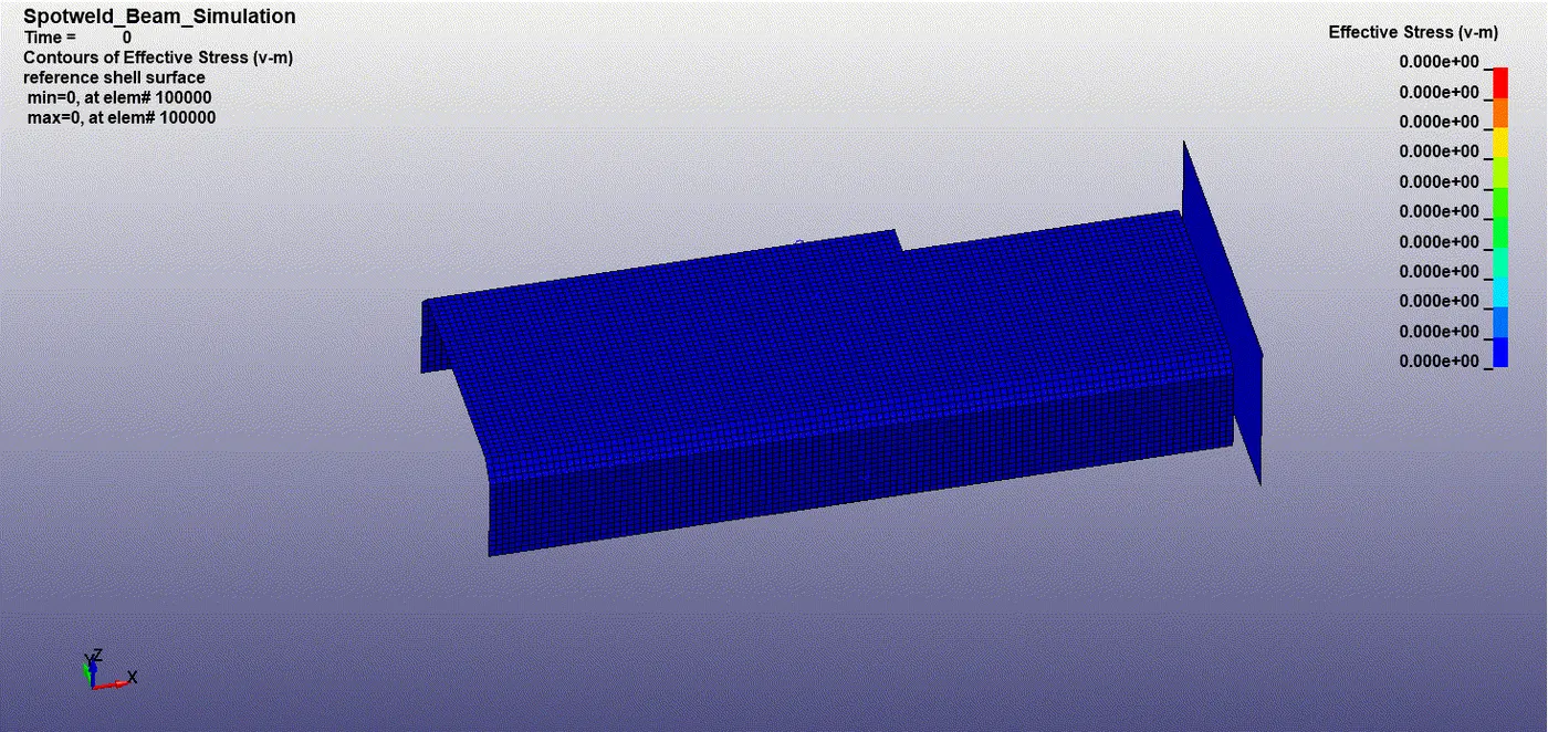
From the above Von-Mises stress contour it is clear that the stress concentration around the weld regions is significant in both the cases. After the weld failure the stress is distributed over the brackets. The peak value of stress is higher for hexa spotwelds in comparison with beam elements. This is due to higher stiffness of the hexa welds.
3. The effective plastic strain contours are shown in the figures below
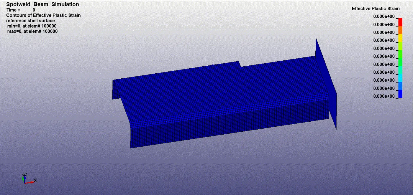
From the effective plastic strain contours it can be inferred that the strain is higher for case 2 with a value of 0.085 and for case 1 the peak value obtained is 0.013.
4. The energy plots obtained are shown in the figures below.
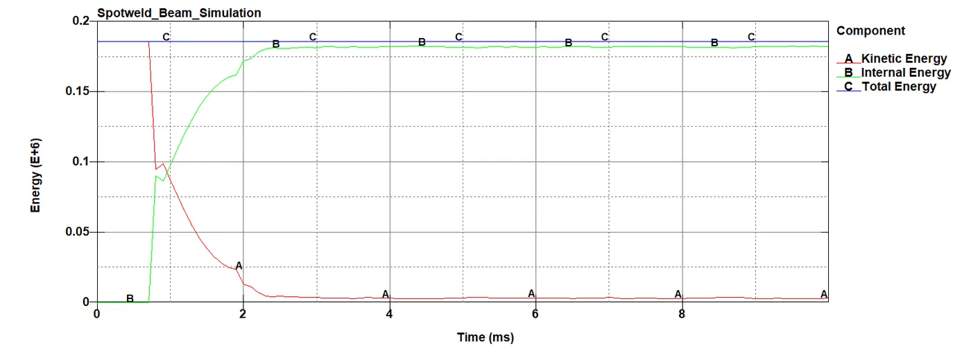
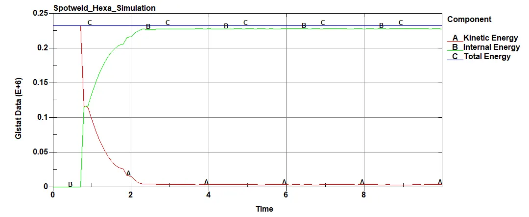
From the energy plots, it is clear that the total energy for hexa spotwelds is higher when compared to beam spotwelds. At around 0.8 ms the impact against the wall happens. This causes reduction of kientic energy associated with increase in internal energy. There is a bump observed in the intersection region of the energies. This is due to inertia effect of the brackets.
5. The stress vs time plots are shown in the figures below.
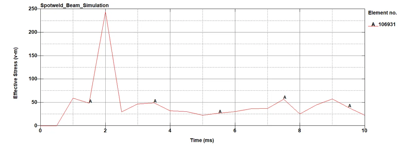
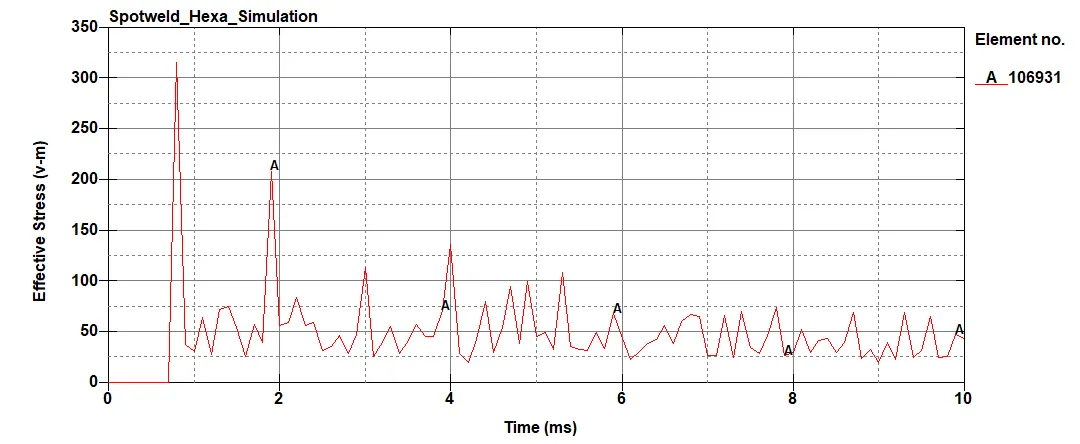
From the above plots it is clear that stresses are higher for hexa spotwelds. The element ID 106931 coressponds to lower bracket near the wall impact region. The stresses obtained are 230 MPa and 330 MPa for beam and hexa spotwelds respectively.
6. The strain vs time plots are shown in the fiugres below
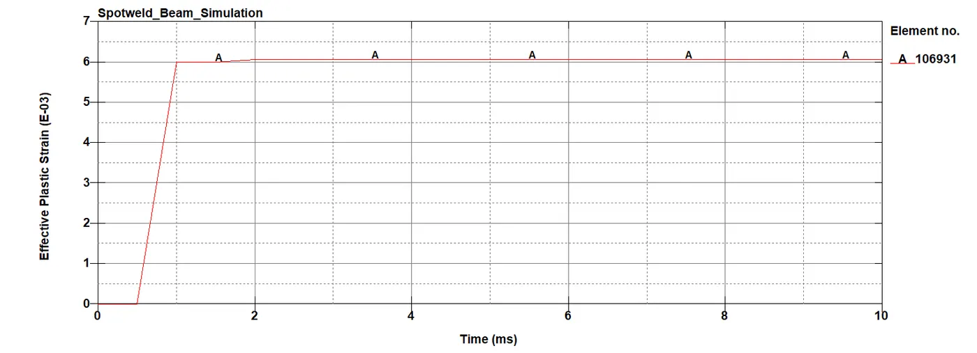
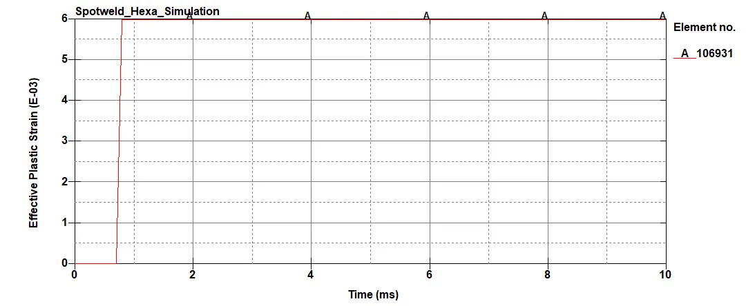
The strain plots remains fairly constant for the two cases. The strain value increases during the time of impact and after which it remains constant.
7. The velocity plots are shown in the figures below
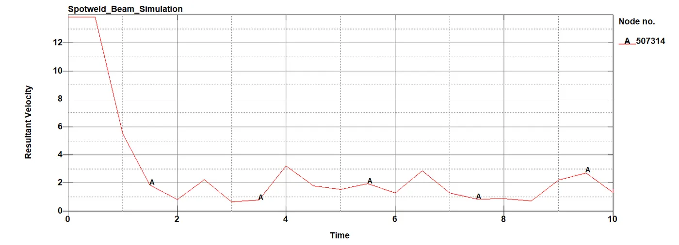
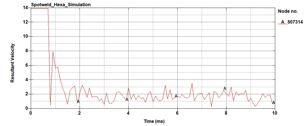
The velocity assigned is 13.889 mm/ms. At the time of impact the velocity drops and after which it oscillates to a particular value. However, for beam spotwelds the velocity drop is smooth when compared to hexa spotwelds.
8. The accleleration plots are shown in the figures below
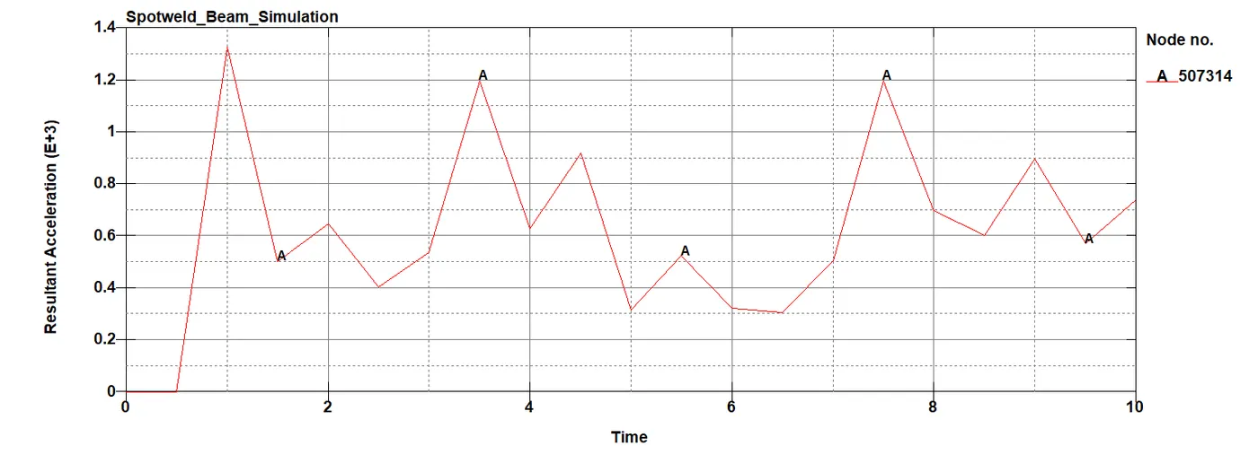
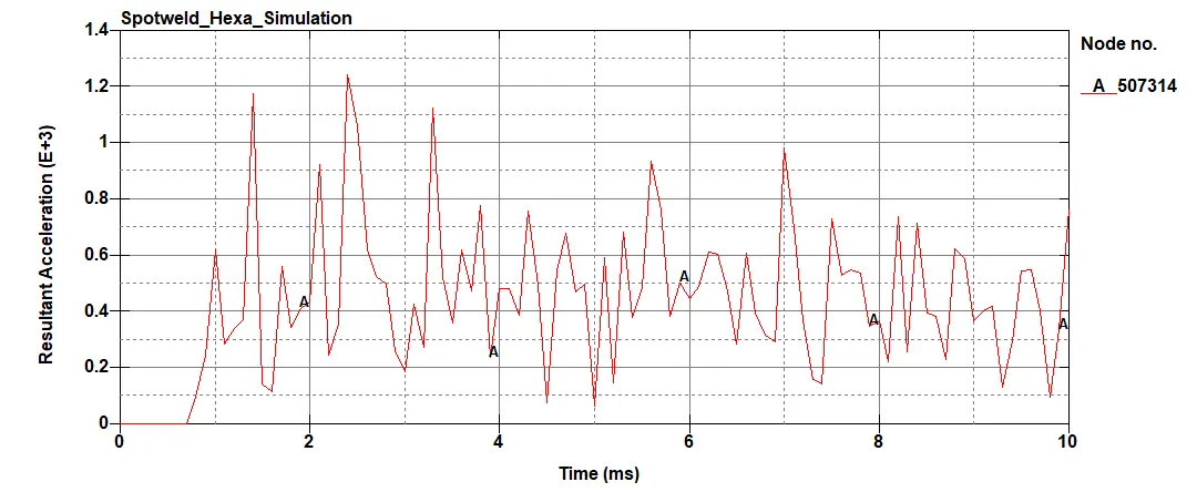
As observed in velocity plots, the acceleration plot for hexa spotwelds is more oscillating when compared to beam elements. The acceleration increases after the impact as shown in the plot. The peak acceleration fairly remains the same for the two cases.
8. The sectional forces obtained are shown in the figures below.
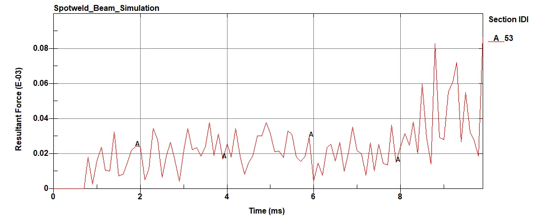
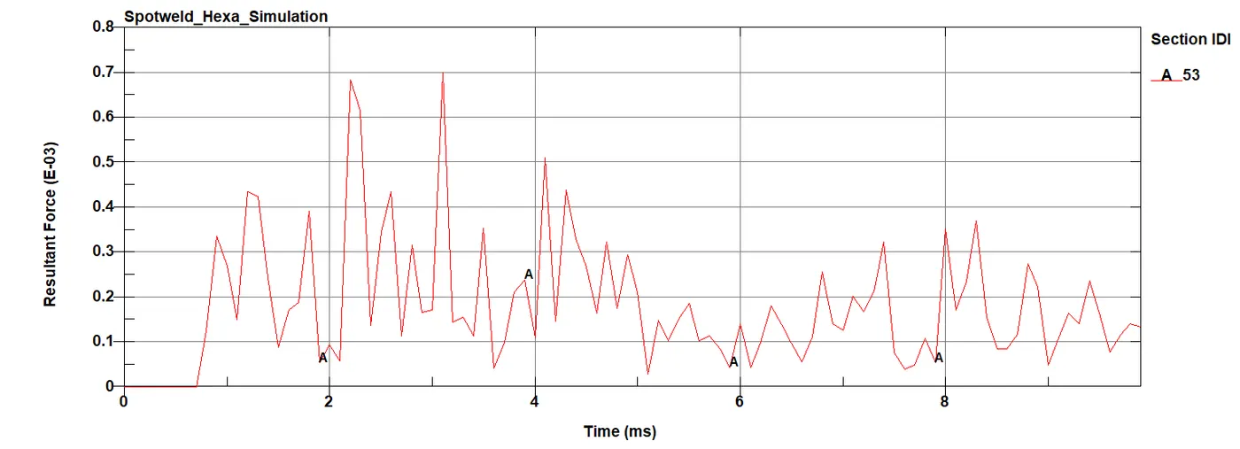
The sectional force obtained is higher for hexa spotwelds. It can be inferred that the force transmitted to the top bracket is more from hexa elements in comparison with beam elements. The cross section chosen is over the weld elements.
9. The spotwelds axial forces are shown in the figures below.
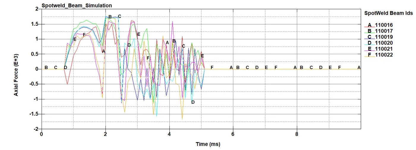
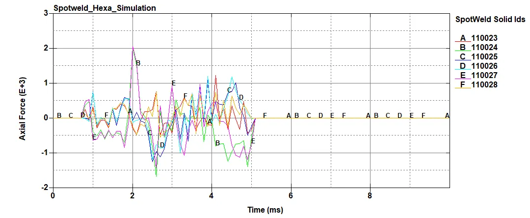
Due to higher stiffness, the axial force is higher for hexa elements in comparison with beam elements as inferred from the plot.
10. The shear forces for the beam elements are shown in the figures below
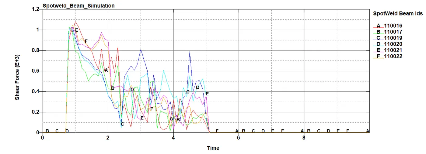
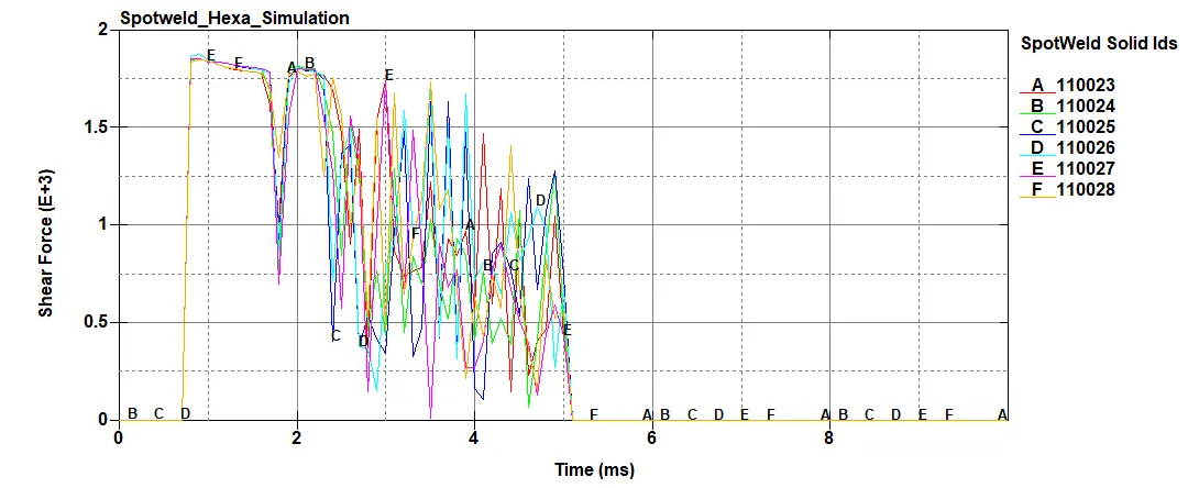
From the above plots, the shear force obtained is higher for hexa elements with a value of 1850 N.
11. The resultant forces are shown in the figures below.
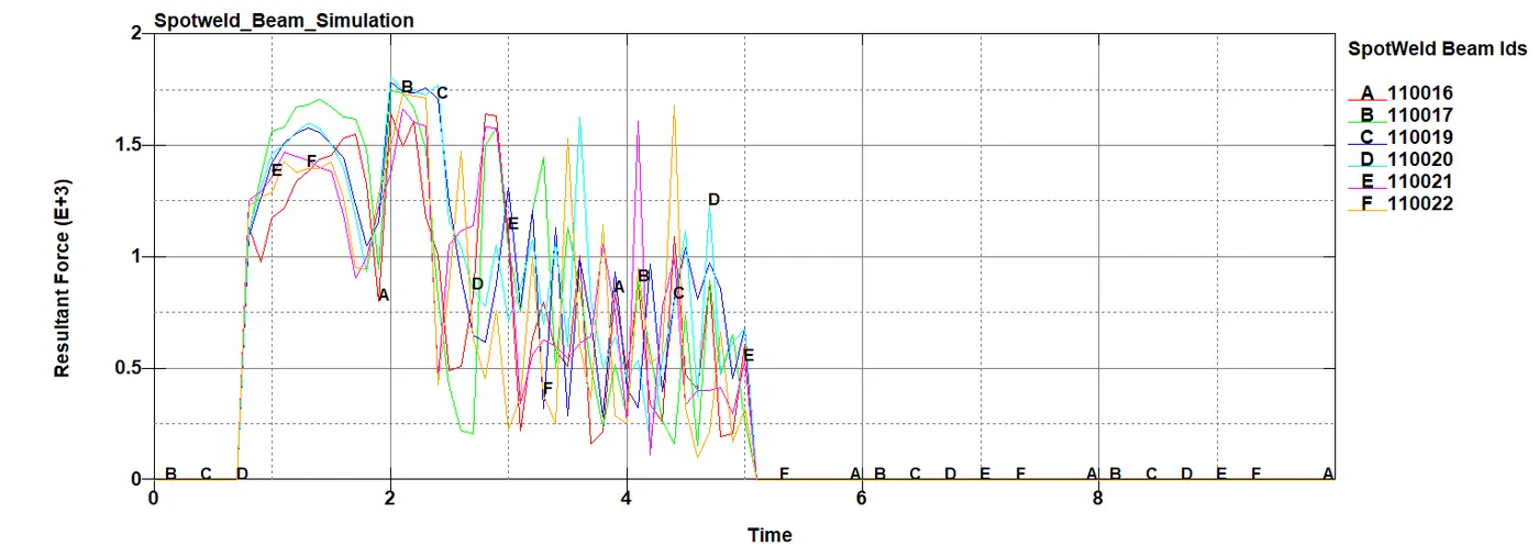
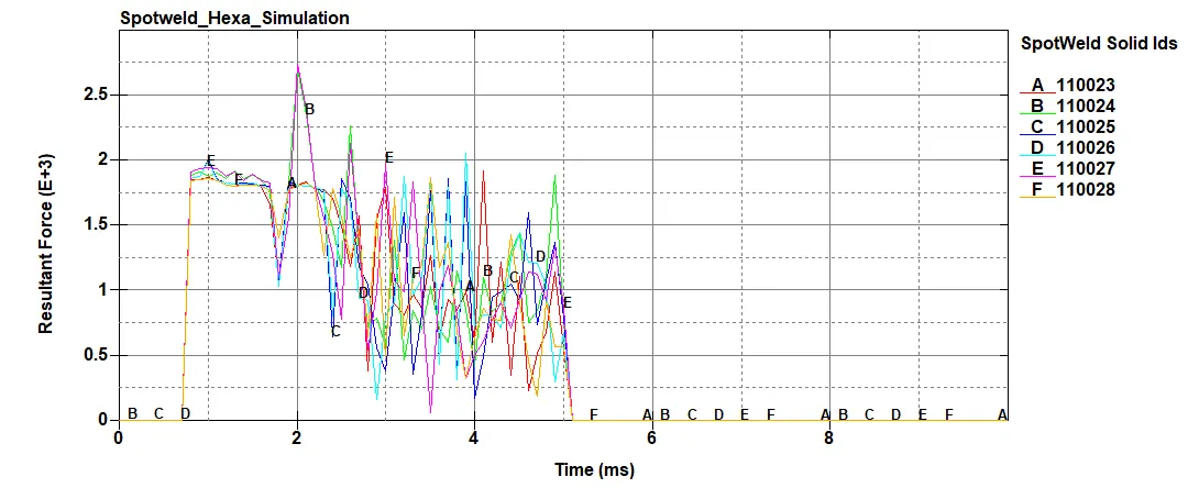
The resultant value of force obtained for beam and hexa elements are 1500 N and 2750 N respectively.
12. The directional stress and strain obtained along different axes is tabulated below:
| Stress (in MPa) | Strain Rate | |||||
| X-Axis | Y-Axis | Z-Axis | X-Axis | Y-Axis | Z-Axis | |
| Beam Elements | 206.44 (Element No: 108061) | 154.82 (Element No: 108621) | 70.006 (Element No: 106005) |
0.443 (Element No: 106759) |
0.236 (Element No: 106659) | 0.253 (Element No: 109823) |
| Hexa Elements | 241.12 (Element No: 107732) | 149.17 (Element No: 110024) | 167.63 (Element No: 110024) | 0.41 (Element No: 107606) | 0.24 (Element No: 107274) | 0.22 (Element No: 109039) |
NOTE:
1. All the time units in the plots are in milliseconds
2. The results vary with the selection of material and the velocity assigned.
3. The above tabulated values gives only the magnitude of stress and strain. It does not state whether it is compressive or tensile forces. These values are obtained by animating the simulation and analysing it frame by frame. The strain values shown here are elastic strain.
4. It is not possible to get accurate maximum directional stress and strain for the overall simulation. This is because only an element can be defined and analysed in LS-Dyna. Also, global values are not a major consideration since it does not predict the failure. It simply gives the maximum value. But the purpose of the simulation is to know the deforming region.
5. The simulation time for hexa spotwelds is higher when compared to beam elements. This is because of usage of solid elements in the model.
CONCLUSION:
The case setup was done as per the objective and the corresponding output requests are obtained. The two cases were discussed and the plots and results were compared accordingly as given in the problem statement.
Drive Link: https://drive.google.com/drive/folders/1Rnk51Mr37iq8i1b0vcWMqZT_7OU5xqqR?usp=sharing