Simulation of Worm Gear using ANSYS Workbench
OBJECTIVE:
To perform transient structural simulation in the given worm gear assembly using ANSYS Workbench. The following objectives have to be satisfied.
1. To cut the model to half to bring it within academic limits
2. The worm should be rotated to the end of the half cut.
3. The equivalent stress, equivalent elastic strain, and the total deformation has to be discussed
PROCEDURE FOR CASE SETUP:
1. Open ANSYS >> Drag and drop transient structural in the project schematic window. Go to space claim and create a plane to cut the gear into half. Cut the gear in the desired plane.
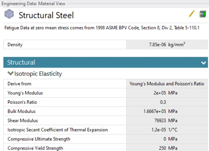
2. Go to engineering data for defining the materials given in the problem. For this simulation, structural steel material is chosen which is the default material. This is shown in the figure below.
3. Select the model tab to establish the meshing, contact definitions, and analysis settings definition. Rename the parts according to convenience.
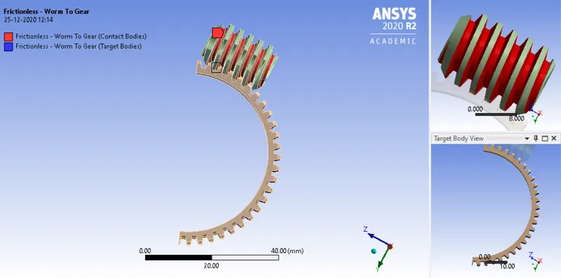
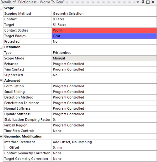
4. Go to contact and rename it based on the definition. Now, create a frictionless contact between worm and gear. Select the additional faces of the gear for the target surfaces.
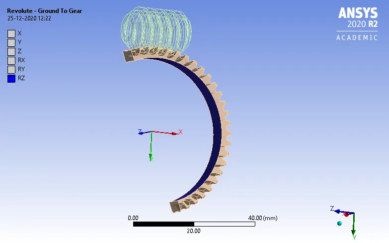
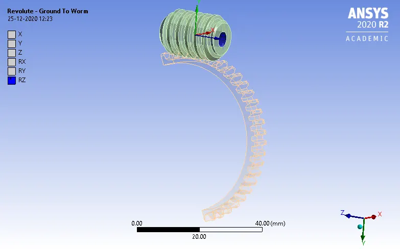
5. A revolute joint is defined for the worm and the gear. This is shown in the figure below.
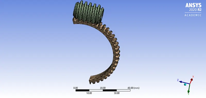
6. For meshing, the default element size is taken for the entire model. The adaptive sizing is turned on during meshing. The final meshed model is shown in the figure below.
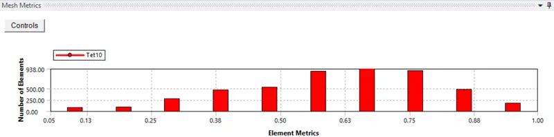
The mesh metrics are shown in the figure below.
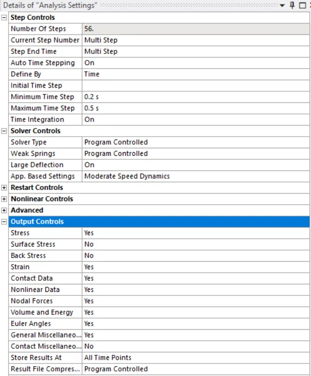
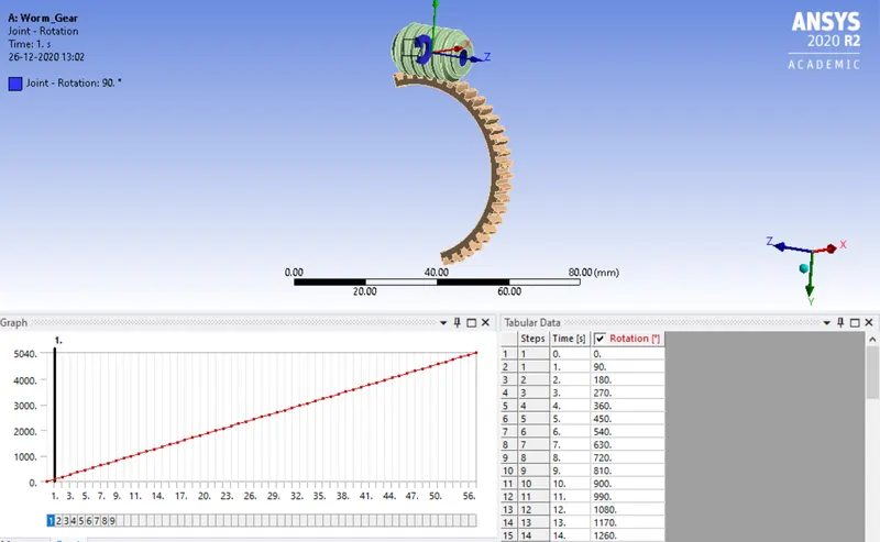
7. Go to analysis settings. The number of steps defined for this analysis is 56. For all the time steps, the definition is shown in the figure below.
8. The boundary conditions are shown in the figure below.
9. The output requests for equivalent stress, equivalent elastic strain, and total deformation are placed.
10. From the analysis settings, hit on solve to start the simulation.
RESULTS AND DISCUSSION:
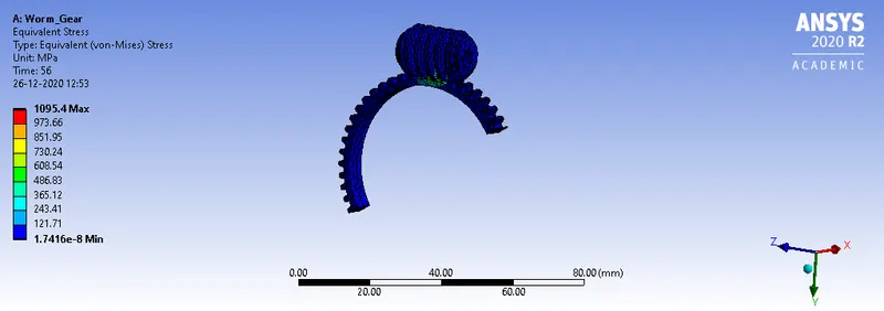
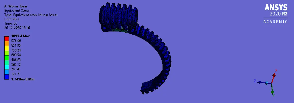
1. The equivalent stress obtained is shown in the figure below.
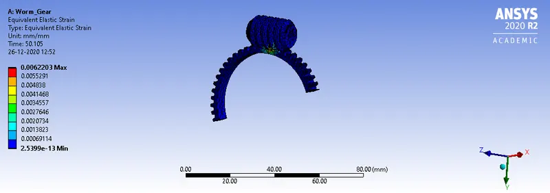
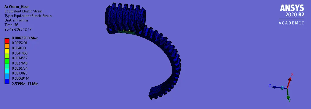
2. The equivalent elastic strain obtained is shown in the figure below.
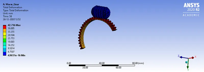
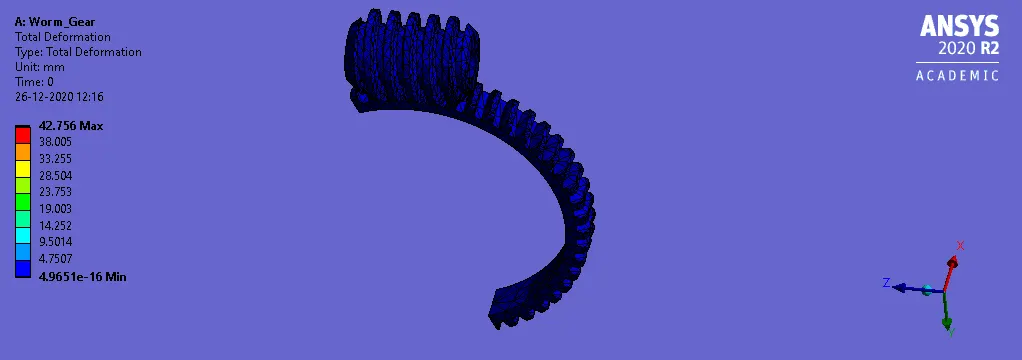
3. The total deformation is shown in the figure below.
ANIMATION FILES:
1. The equivalent stress obtained is shown in the figure below.
2. The equivalent elastic strain obtained is shown in the figure below.
3. The total deformation is shown in the figure below.
CONCLUSION:
From the simulation, it can be seen that the solution converged without any errors.
Also, due to the increase in time step the run time of simulation is longer than the expected value. At a particular step, if the joint rotation exceeds 100 degrees there is an error observed in the convergence. So, the joint rotation is defined as 90 degrees for each time step.
From the results, it can be seen that the total deformation obtained is 42.756 mm. The equivalent stress obtained is 1095.4 MPa. The elastic strain obtained is 0.00622.
Hence, all the objectives are satisfied in the challenge.