Week- 5 - Solid meshing
OBJECTIVE:
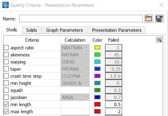
To perform solid meshing in the given rearview mirror component as per the quality criteria given below using ANSA.
2D Element Quality Criteria:
|
S.No |
Quality Criteria |
Value |
|
1 |
Target/Average length |
1 |
|
2 |
Minimum Length |
0.5 |
|
3 |
Maximum Length |
2 |
Volume Meshing Quality Criteria:
|
S.No |
Quality Criteria |
Value |
|
1 |
Tet collapse |
0.2 |
PROCEDURE:
1. The given model is imported into the ANSA software. Go to Topo>>Faces>>Orient>>Select the geometry and apply the settings. This is shown in the figure below.
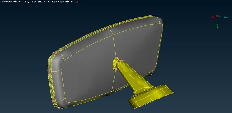
2. Go to Topo>>Faces>>Topo. Select the geometry and the selection is confirmed. After doing topo, the obtained geometry is shown in the figure below.
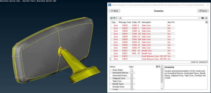
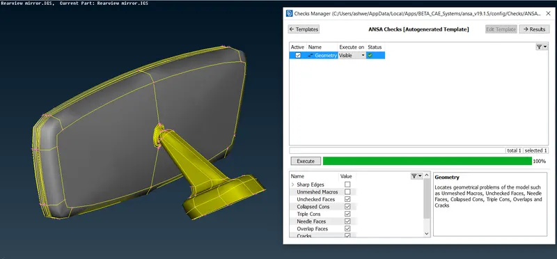
3. Now go to Checks Manager>>Geometry. Select the visible geometry and run. There are various errors found in the model. Select all the errors and give the fix option. Now the check is again run on the model. All the errors are fixed either by using the fix option or by using the Topo option. These are shown in the figure below.
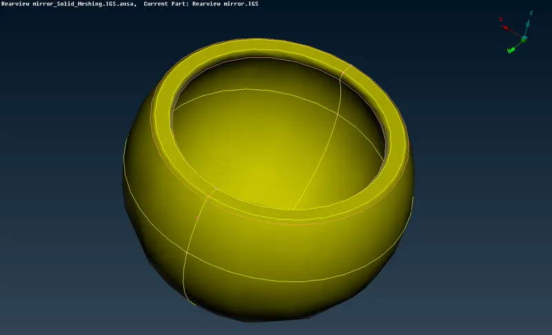
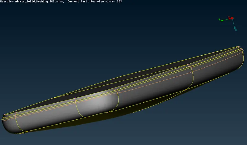
4. Some of the areas are defeatured to get mesh quality. This is shown in the figure below. Go to Mesh>>Perimeters>>Length. Select the geometry and set the length and macro to be 1.
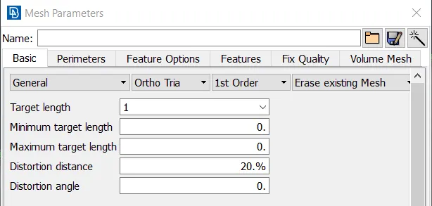
5. Go to quality criteria settings. Enter the quality criteria as given in the objective. In the mesh parameters enter the desired size of the mesh. This is shown in the figure below.
6. Go to Mesh>>Mesh Generation>>Spot Mesh>>Select the faces of the geometry in which large curvature is there and keep the element type as Ortho Tria. For the flat faces select Tria option and generate the mesh. The mesh is generated as shown in the figure below.
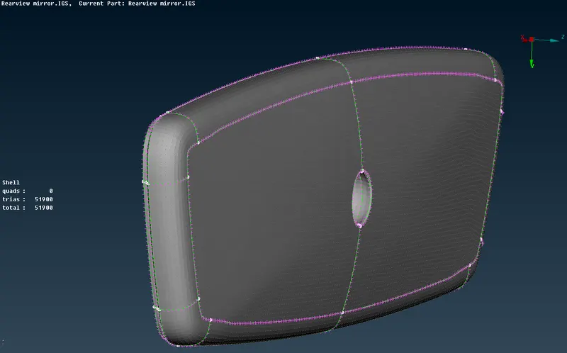
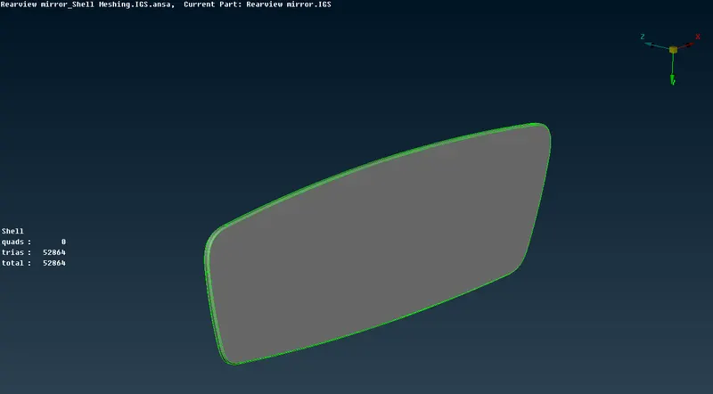
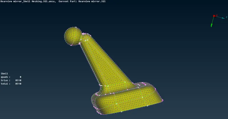
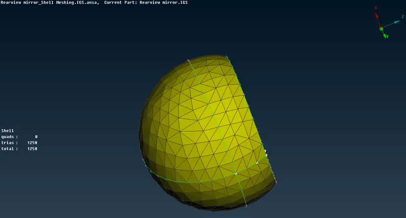
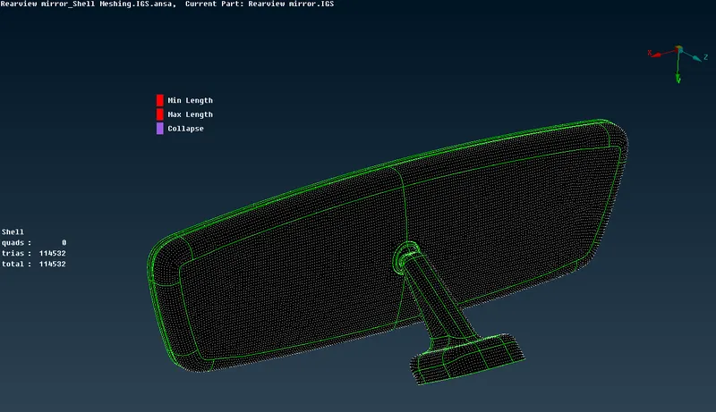
7. The quality criteria is checked and fixed. The 2D mesh after fixing the quality criteria is shown below.
8. Go to Volume Mesh>>Volumes>>Define>>Manual. Select the four sub parts and define the volume. The property card is defined as PSOLID. It is shown in the figure below.
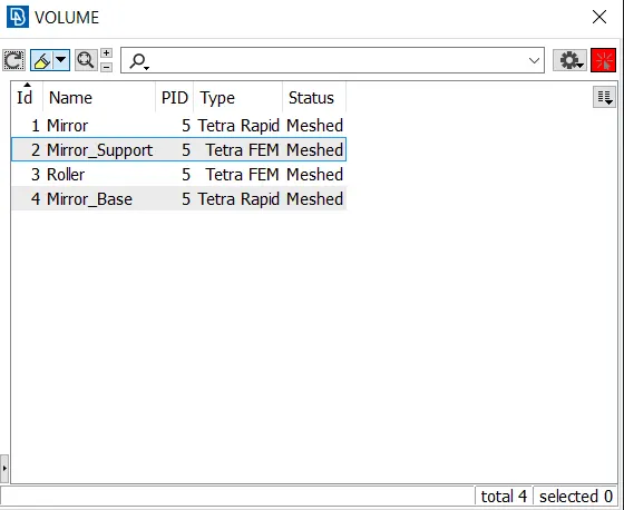
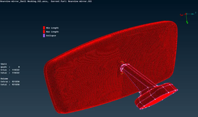
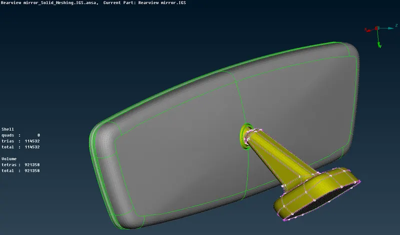
9. Go to Volume Mesh>>Unstructured Mesh>>Select either Tetra Rapid or Tetra FEM for meshing the parts. After meshing, the quality criteria is checked and fixed. The cut section after 3D mesh is shown in the figures below.
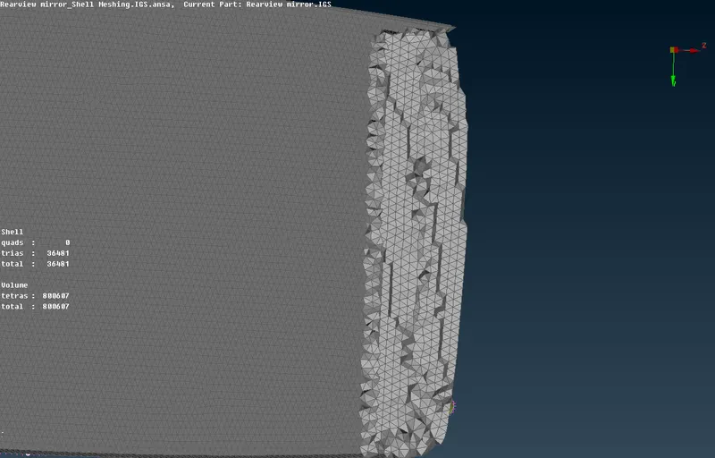
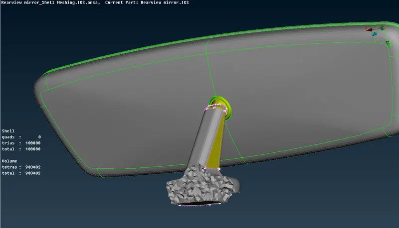
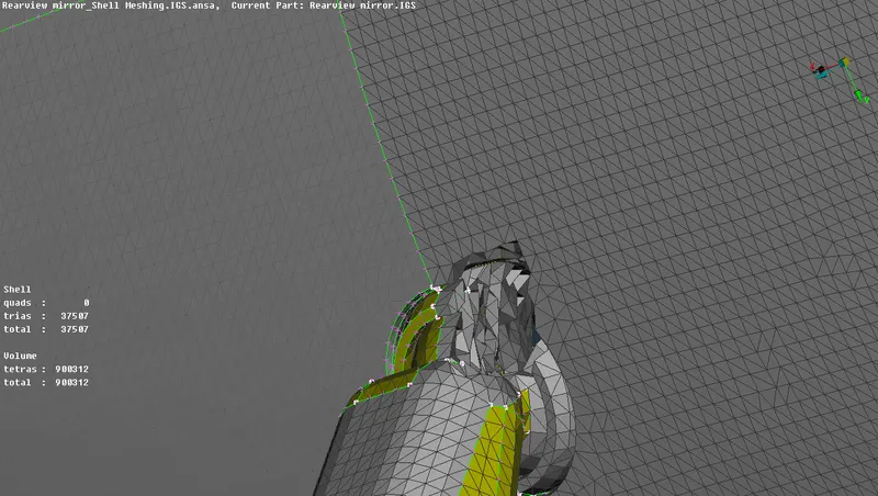
10. The final meshed model after quality checks is shown in the figure below. The 3D mesh is check using bounds option.
LEARNING OUTCOME:
1. Usage of ortho trias and trias in shell meshing is learnt. Ortho trias has to be used in the fillet areas for better feature capturing.
2. Unstructured 3D meshing using Tetra Rapid and Tetra FEM is learnt.
3. Learned about various mesh quality improvisation techniques like MV Free option, Grids>>Paste options.
CONCLUSION:
Solid meshing is done in the given rear view mirror model as per the given quality criteria. Hence, all the objectives are satisfied.