Week 11 Car Crash simulation
OBJECTIVE:
To perform a car crash simulation (explicit analysis) using ANSYS Workbench. The analysis has to be carried out using different thicknesses for the car body.
PROCEDURE FOR CASE SETUP:
1. Open ANSYS >> Drag and drop explicit analysis in the project schematic window.
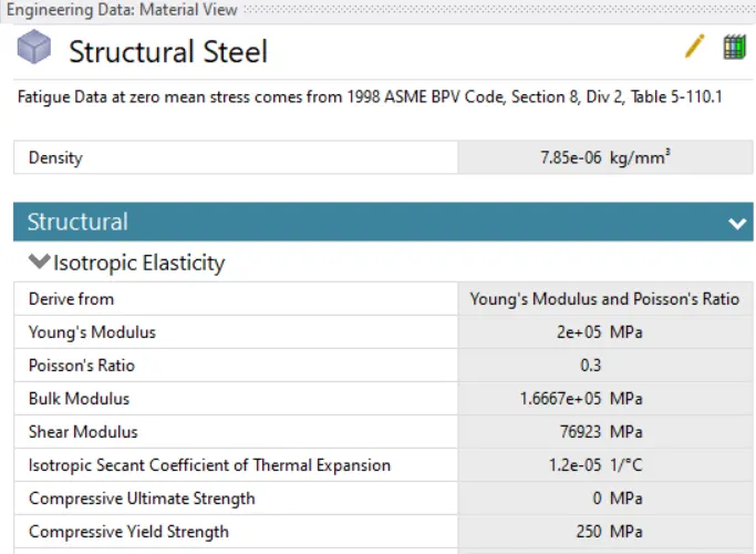
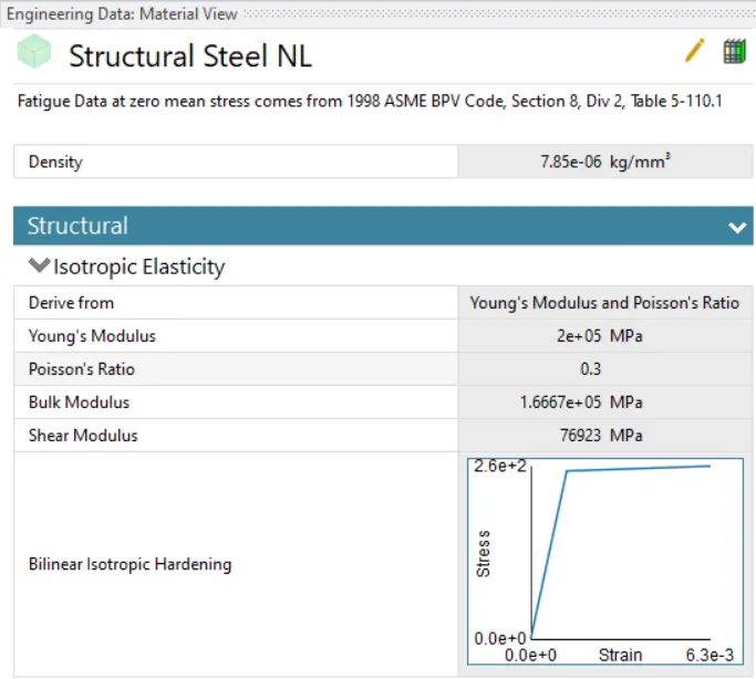
2. Go to engineering data for defining the materials given in the problem. From the general non-linear materials select Structural Steel NL from the library. The material is shown in the figure below. The structural steel NL has to be assigned to the car body.
3. Select the model tab to establish the meshing, contact definitions, and analysis settings definition. Rename the parts according to convenience.
4. Go to contact and delete the default contacts.
5. For meshing, using the patch conforming method changing the element type to be tetrahedrons for the wall. Select the faces shown in the figure and give a size of 175 mm. Using the patch conforming method select the car body and give the type to be triangles.
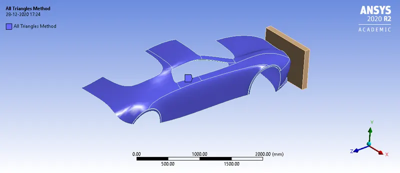
The final meshed model is shown in the figure below.
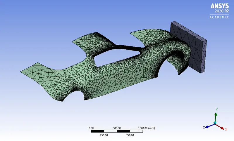
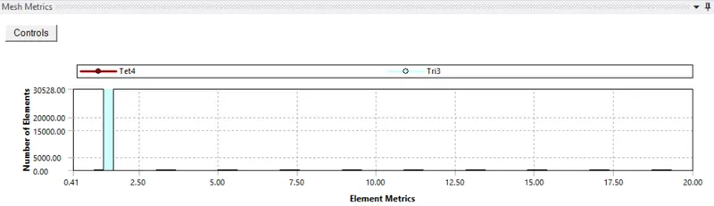
The mesh metrics are shown in the figure below.
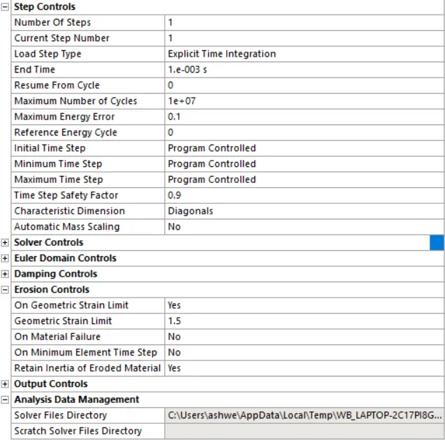
6. Go to analysis settings. The total run time is defined to be 0.001 seconds.
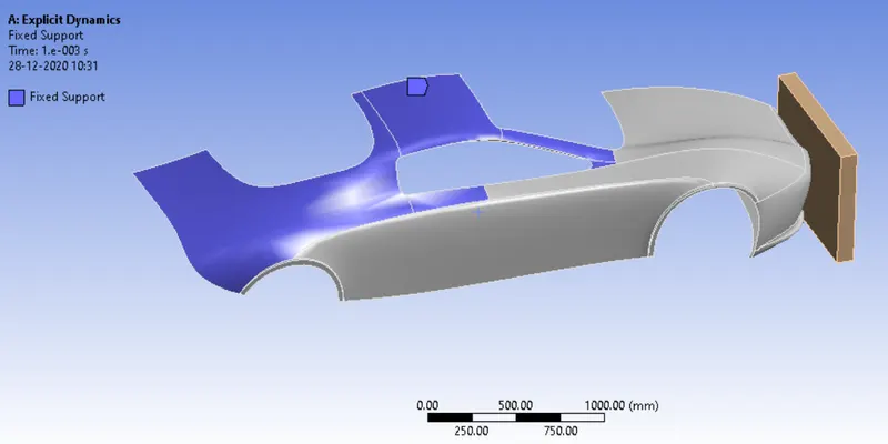
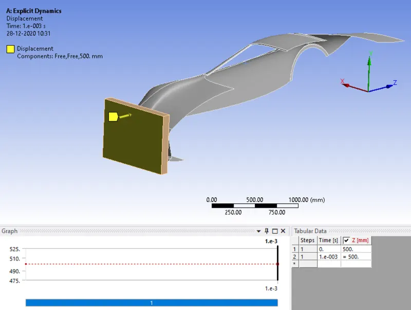
7. The boundary conditions are shown in the figures below.
8. Go to the Model tab, use the symmetry option for the wall and the car body. This is shown in the figure below.
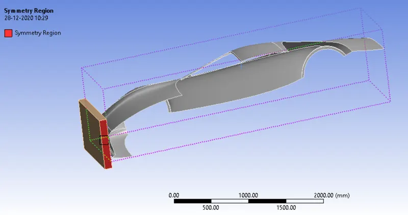
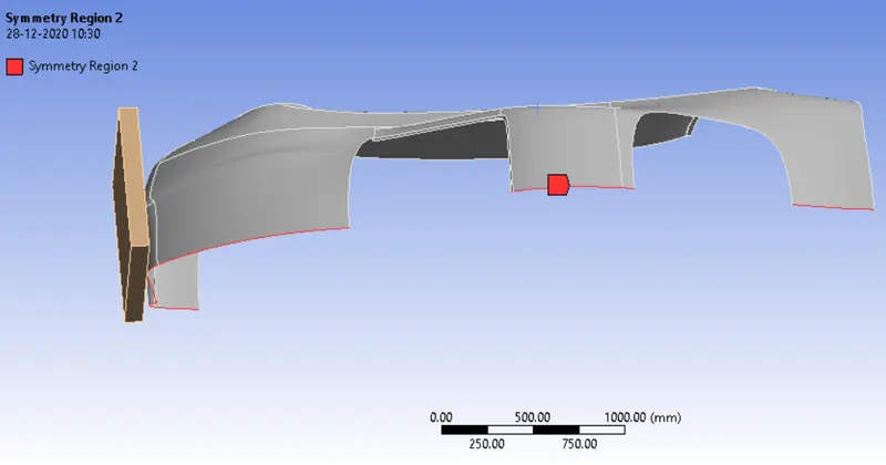
9. The output requests for equivalent stress and total deformation are placed.
10. From the analysis settings, hit on solve to start the simulation.
RESULTS AND DISCUSSION:
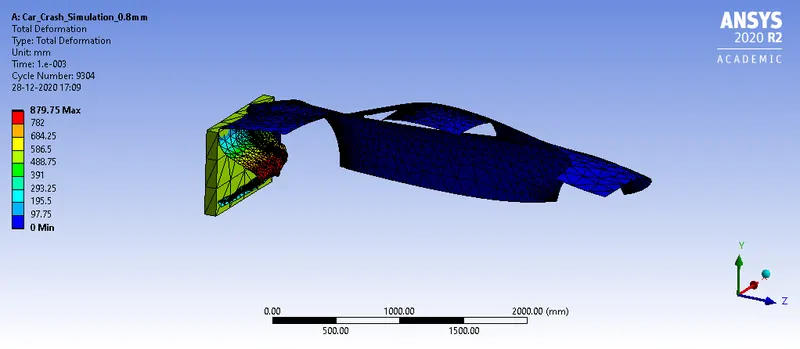
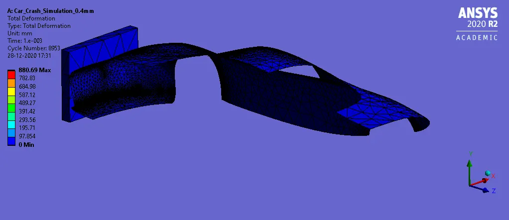
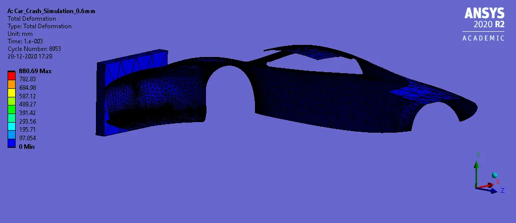
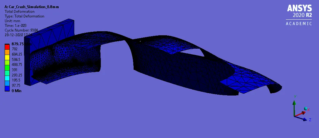
1. The total deformation obtained is shown below.
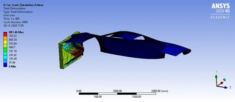
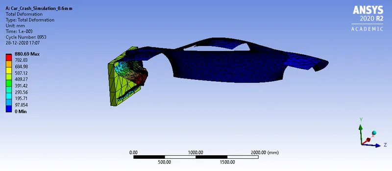
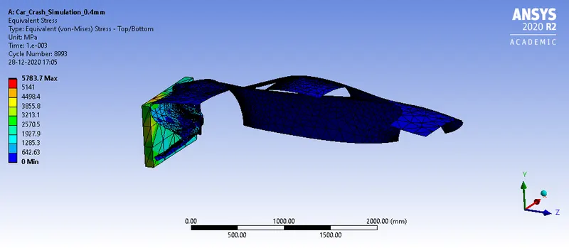
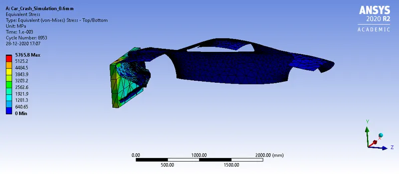
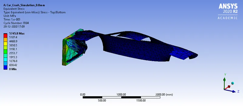
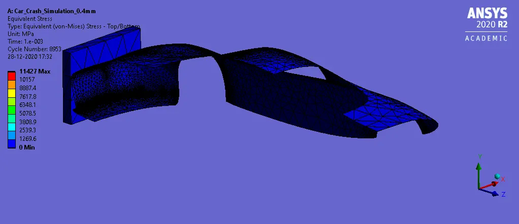
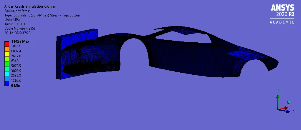
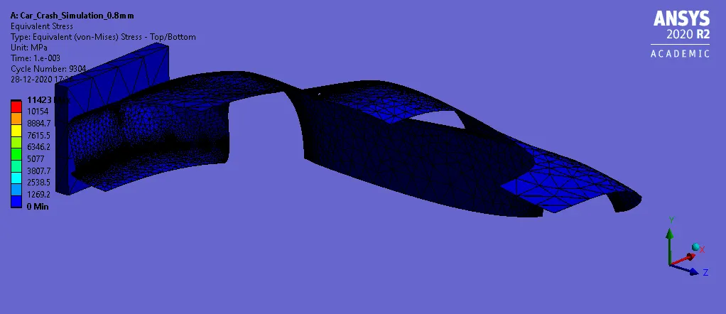
2. The equivalent stress obtained is shown in the figure below.
ANIMATION FILES:
1. The total deformation obtained is shown below
2. The Von-Mises stress obtained is shown in the figures below.
RESULTS AND DISCUSSION:
From the simulation, it can be seen that for all the cases the solution converged without any errors.
The output parameters are tabulated below.
| Thickness of car body | Total Deformation (in mm) | Equivalent Stress (in MPa) |
| 0.4 mm | 881.46 | 5783.7 |
| 0.6 mm | 880.69 | 5765.8 |
| 0.8 mm | 879.75 | 5745.8 |
The results obtained from the parametric study are shown below.

From the above table, it can be seen that the total deformation reduces as the thickness increases. For a thickness of 0.8 mm, the total deformation obtained is 879.75 mm. For a thickness of 0.4 mm, the thickness obtained is 881.46 mm.
Also, the value of equivalent stress reduces as the thickness increases. For a thickness of 0.8 mm, the equivalent stress obtained is 5745.8 MPa. For a thickness of 0.4 mm, the equivalent stress obtained is 5783.7 MPa.
It can be concluded that with the increase in thickness the value of total deformation and equivalent stress decreases. Hence, all the objectives are satisfied.